EP0482379A1 - Système de freinage hydraulique à plusieurs circuits, notamment pour véhicules automobiles - Google Patents
Système de freinage hydraulique à plusieurs circuits, notamment pour véhicules automobiles Download PDFInfo
- Publication number
- EP0482379A1 EP0482379A1 EP91116566A EP91116566A EP0482379A1 EP 0482379 A1 EP0482379 A1 EP 0482379A1 EP 91116566 A EP91116566 A EP 91116566A EP 91116566 A EP91116566 A EP 91116566A EP 0482379 A1 EP0482379 A1 EP 0482379A1
- Authority
- EP
- European Patent Office
- Prior art keywords
- brake
- wheel
- line
- valve arrangement
- pressure
- Prior art date
- Legal status (The legal status is an assumption and is not a legal conclusion. Google has not performed a legal analysis and makes no representation as to the accuracy of the status listed.)
- Granted
Links
- 230000000903 blocking effect Effects 0.000 claims description 16
- 238000012423 maintenance Methods 0.000 claims description 4
- 230000000694 effects Effects 0.000 claims description 3
- 230000002093 peripheral effect Effects 0.000 description 3
- 230000006399 behavior Effects 0.000 description 2
- 238000011161 development Methods 0.000 description 2
- 230000018109 developmental process Effects 0.000 description 2
- 230000001960 triggered effect Effects 0.000 description 2
- 230000000712 assembly Effects 0.000 description 1
- 238000000429 assembly Methods 0.000 description 1
- 238000010586 diagram Methods 0.000 description 1
- 238000011156 evaluation Methods 0.000 description 1
- 238000009987 spinning Methods 0.000 description 1
- 230000028838 turning behavior Effects 0.000 description 1
Images
Classifications
-
- B—PERFORMING OPERATIONS; TRANSPORTING
- B60—VEHICLES IN GENERAL
- B60T—VEHICLE BRAKE CONTROL SYSTEMS OR PARTS THEREOF; BRAKE CONTROL SYSTEMS OR PARTS THEREOF, IN GENERAL; ARRANGEMENT OF BRAKING ELEMENTS ON VEHICLES IN GENERAL; PORTABLE DEVICES FOR PREVENTING UNWANTED MOVEMENT OF VEHICLES; VEHICLE MODIFICATIONS TO FACILITATE COOLING OF BRAKES
- B60T8/00—Arrangements for adjusting wheel-braking force to meet varying vehicular or ground-surface conditions, e.g. limiting or varying distribution of braking force
- B60T8/32—Arrangements for adjusting wheel-braking force to meet varying vehicular or ground-surface conditions, e.g. limiting or varying distribution of braking force responsive to a speed condition, e.g. acceleration or deceleration
- B60T8/34—Arrangements for adjusting wheel-braking force to meet varying vehicular or ground-surface conditions, e.g. limiting or varying distribution of braking force responsive to a speed condition, e.g. acceleration or deceleration having a fluid pressure regulator responsive to a speed condition
- B60T8/48—Arrangements for adjusting wheel-braking force to meet varying vehicular or ground-surface conditions, e.g. limiting or varying distribution of braking force responsive to a speed condition, e.g. acceleration or deceleration having a fluid pressure regulator responsive to a speed condition connecting the brake actuator to an alternative or additional source of fluid pressure, e.g. traction control systems
- B60T8/4809—Traction control, stability control, using both the wheel brakes and other automatic braking systems
- B60T8/4827—Traction control, stability control, using both the wheel brakes and other automatic braking systems in hydraulic brake systems
- B60T8/4863—Traction control, stability control, using both the wheel brakes and other automatic braking systems in hydraulic brake systems closed systems
- B60T8/4872—Traction control, stability control, using both the wheel brakes and other automatic braking systems in hydraulic brake systems closed systems pump-back systems
-
- B—PERFORMING OPERATIONS; TRANSPORTING
- B60—VEHICLES IN GENERAL
- B60T—VEHICLE BRAKE CONTROL SYSTEMS OR PARTS THEREOF; BRAKE CONTROL SYSTEMS OR PARTS THEREOF, IN GENERAL; ARRANGEMENT OF BRAKING ELEMENTS ON VEHICLES IN GENERAL; PORTABLE DEVICES FOR PREVENTING UNWANTED MOVEMENT OF VEHICLES; VEHICLE MODIFICATIONS TO FACILITATE COOLING OF BRAKES
- B60T8/00—Arrangements for adjusting wheel-braking force to meet varying vehicular or ground-surface conditions, e.g. limiting or varying distribution of braking force
- B60T8/17—Using electrical or electronic regulation means to control braking
- B60T8/175—Brake regulation specially adapted to prevent excessive wheel spin during vehicle acceleration, e.g. for traction control
-
- B—PERFORMING OPERATIONS; TRANSPORTING
- B60—VEHICLES IN GENERAL
- B60T—VEHICLE BRAKE CONTROL SYSTEMS OR PARTS THEREOF; BRAKE CONTROL SYSTEMS OR PARTS THEREOF, IN GENERAL; ARRANGEMENT OF BRAKING ELEMENTS ON VEHICLES IN GENERAL; PORTABLE DEVICES FOR PREVENTING UNWANTED MOVEMENT OF VEHICLES; VEHICLE MODIFICATIONS TO FACILITATE COOLING OF BRAKES
- B60T8/00—Arrangements for adjusting wheel-braking force to meet varying vehicular or ground-surface conditions, e.g. limiting or varying distribution of braking force
- B60T8/17—Using electrical or electronic regulation means to control braking
- B60T8/176—Brake regulation specially adapted to prevent excessive wheel slip during vehicle deceleration, e.g. ABS
- B60T8/1761—Brake regulation specially adapted to prevent excessive wheel slip during vehicle deceleration, e.g. ABS responsive to wheel or brake dynamics, e.g. wheel slip, wheel acceleration or rate of change of brake fluid pressure
- B60T8/17616—Microprocessor-based systems
-
- B—PERFORMING OPERATIONS; TRANSPORTING
- B60—VEHICLES IN GENERAL
- B60T—VEHICLE BRAKE CONTROL SYSTEMS OR PARTS THEREOF; BRAKE CONTROL SYSTEMS OR PARTS THEREOF, IN GENERAL; ARRANGEMENT OF BRAKING ELEMENTS ON VEHICLES IN GENERAL; PORTABLE DEVICES FOR PREVENTING UNWANTED MOVEMENT OF VEHICLES; VEHICLE MODIFICATIONS TO FACILITATE COOLING OF BRAKES
- B60T8/00—Arrangements for adjusting wheel-braking force to meet varying vehicular or ground-surface conditions, e.g. limiting or varying distribution of braking force
- B60T8/32—Arrangements for adjusting wheel-braking force to meet varying vehicular or ground-surface conditions, e.g. limiting or varying distribution of braking force responsive to a speed condition, e.g. acceleration or deceleration
- B60T8/88—Arrangements for adjusting wheel-braking force to meet varying vehicular or ground-surface conditions, e.g. limiting or varying distribution of braking force responsive to a speed condition, e.g. acceleration or deceleration with failure responsive means, i.e. means for detecting and indicating faulty operation of the speed responsive control means
- B60T8/92—Arrangements for adjusting wheel-braking force to meet varying vehicular or ground-surface conditions, e.g. limiting or varying distribution of braking force responsive to a speed condition, e.g. acceleration or deceleration with failure responsive means, i.e. means for detecting and indicating faulty operation of the speed responsive control means automatically taking corrective action
- B60T8/96—Arrangements for adjusting wheel-braking force to meet varying vehicular or ground-surface conditions, e.g. limiting or varying distribution of braking force responsive to a speed condition, e.g. acceleration or deceleration with failure responsive means, i.e. means for detecting and indicating faulty operation of the speed responsive control means automatically taking corrective action on speed responsive control means
-
- B—PERFORMING OPERATIONS; TRANSPORTING
- B60—VEHICLES IN GENERAL
- B60T—VEHICLE BRAKE CONTROL SYSTEMS OR PARTS THEREOF; BRAKE CONTROL SYSTEMS OR PARTS THEREOF, IN GENERAL; ARRANGEMENT OF BRAKING ELEMENTS ON VEHICLES IN GENERAL; PORTABLE DEVICES FOR PREVENTING UNWANTED MOVEMENT OF VEHICLES; VEHICLE MODIFICATIONS TO FACILITATE COOLING OF BRAKES
- B60T2270/00—Further aspects of brake control systems not otherwise provided for
- B60T2270/20—ASR control systems
- B60T2270/203—ASR control systems hydraulic system components
Definitions
- the invention is based on a hydraulic multi-circuit brake system according to the preamble of the main claim.
- Such a hydraulic multi-circuit brake system is already known (DE-OS 37 41 310, Figure 1), in which the first valve arrangement of the wheel brake assigned to the non-driven vehicle wheel consists of two 2/2-way valves, of which the so-called intake valve in the Brake line is located, while the so-called outlet valve has the third connection of the first valve arrangement and is located in an outflow line which extends from the brake line between the inlet valve and the wheel brake and leads to the inlet side of the pump.
- the two directional control valves of the first valve arrangement are in the open position and the second valve arrangement in the brake line of the driven vehicle wheel are in the blocking position, so that the pump draws pressure medium through the master cylinder from a pressure medium reservoir, into the brake line of the driven vehicle wheel and in the associated wheel brake Can build up brake pressure.
- the outlet valve assuming its open position, the occurrence of harmful negative pressure in the wheel brake cylinder of the non-driven vehicle wheel at the start of the pressure medium delivery is not completely excluded.
- the hydraulic multi-circuit brake system according to the invention with the characterizing features of the main claim has the advantage that, in the case of traction control, an instantaneous braking initiated by the driver is possible because until the third valve arrangement is closed and the second valve arrangement is opened and the first valve arrangement of the non-driven is switched over Vehicle wheel in the pressure purchase position brake pressure from the master brake cylinder through the intake line and the auxiliary brake line can be controlled by overcoming the fourth valve arrangement in the wheel brake of the non-driven wheel. This avoids loss of braking distance.
- the wheel brake of the driven vehicle wheel in the brake circuit is also easily included in the undelayed brake pressure control when braking initiated by the driver.
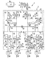
- a hydraulic multi-circuit brake system 1 for motor vehicles shown in the drawing is equipped with an anti-lock and traction control device 2.
- the brake system 1 has a pedal-operated master brake cylinder 3 with a pressure medium reservoir 4 attached.
- a master brake line 5 of a first brake circuit 1 extends from the brake cylinder 3.
- the main brake line 5 is branched into two brake lines 6 and 7.
- the brake line 6 leads to a wheel brake cylinder 8 of a wheel brake 9 of a driven vehicle wheel, not shown.
- the brake line 7 is connected to the wheel brake cylinder 10 of a wheel brake 11 of a non-driven vehicle wheel, also not shown.
- a main brake line 15 of a second brake circuit 11 also extends from the master brake cylinder 3.
- the main brake line 15 is continued in two brake lines 16 and 17.
- the brake line 16 ends at a wheel brake cylinder 18 of the wheel brake 19 of a driven vehicle wheel, not shown.
- the brake line 17 is not in contact with the wheel brake cylinder 20 of the wheel brake 21, also not shown driven vehicle wheel in connection.
- the driven vehicle wheels assigned to the wheel brakes 9 and 19 are associated with a vehicle axle; the non-driven vehicle wheels to which the wheel brakes 11 and 21 are assigned belong to a second axle of the vehicle.
- the assignment of the wheel brakes is selected such that the two wheel brakes 9 and 11 or 19 and 21 of the respective brake circuit 1 or 11 are diagonally opposite one another. Since the two brake circuits I and 11 are identical, only the brake circuit I is described in detail below.
- a first valve arrangement 25 is assigned to the wheel brake 9 of the driven vehicle wheel. This consists of an inlet valve 26 and an outlet valve 27.
- the two valves 26 and 27 are designed as a 2/2-way valve.
- the first valve arrangement 25 can also be designed as a 3/3-way valve, not shown, located in the brake line 6.
- the inlet valve 26 has a spring-operated passage position 26a and an electromagnetically switchable blocking position 26b.
- the outlet valve 27 has a spring-operated blocking position 27a and an electromagnetically switched passage position 27b.
- the first valve arrangement 25 has the following connections: on the inlet valve 26, a first connection 26.1 on the master cylinder side and a second connection 26.2 on the wheel brake side for the brake line 6; at the outlet valve 27 a third connection 27.3 for releasing pressure medium removed from the wheel brake 9, which can be fed to a fourth connection 27.4.
- the first valve arrangement 25 can be switched in the switch position for pressure build-up, pressure maintenance and pressure reduction in the wheel brake cylinder 8 of the wheel brake 9: In the switch position for pressure build-up, as shown, the inlet valve 26 assumes its passage position 26a and the outlet valve 27 its blocking position 27a. In the switch position for maintaining pressure, the inlet valve 26, like the outlet valve 27, is switched into its blocking position 26b. In the switch position for pressure reduction, the inlet valve 26 assumes its blocking position 26b; the outlet valve 27 is switched to the open position 27b.
- the wheel brake 11 of the non-driven vehicle wheel is also assigned a first valve arrangement 28 with an inlet valve 29 and an outlet valve 30.
- the valve arrangement 28 has connections and switching positions for pressure build-up, pressure maintenance and pressure reduction.
- a second valve arrangement 33 is provided in the brake line 6 of the driven vehicle wheel assigned to the wheel brake 9 between the master brake cylinder 3 and the first valve arrangement 25.
- This valve arrangement 33 is designed as a 2/2-way valve and has a spring-operated passage position 33a and an electromagnetic switchable blocking position 33b.
- the brake circuit I is also assigned a self-priming pump 36 with an electric drive motor 37.
- the inlet side 38 of the pump 36 is connected via a return line 39 to the third connection 27.3 or 30.3 of the outlet valves 27 and 30 of the first two valve arrangements 25 and 28 of the brake circuit I.
- a storage chamber 40 for receiving pressure medium removed from the wheel brake cylinders 8 and 10 is connected to the return line 39.
- a delivery line 42 extends from the output side 41 of the pump 36 and is connected between the first valve arrangement 25 and the second valve arrangement 33 to the brake line 6 of the wheel brake 9 of the driven vehicle wheel.
- the inlet side 38 of the pump 36 is also connected by a suction line 45 to the brake line 7 of the wheel brake 11 of the non-driven vehicle wheel, namely between the master brake cylinder 3 and the first valve arrangement 28 located in the brake line 7.
- a third is located in the suction line 45
- Valve arrangement 46 which is designed as a 2/2-way valve.
- the third valve arrangement 46 has a spring-operated blocking position 46a and an electromagnetically switchable passage position 46b.
- An overflow line 49 extends from the brake line 6 between the mouth of the delivery line 42 and the second valve arrangement 33 and is connected to the intake line 45 between the third valve arrangement 46 and the master brake cylinder 3.
- a pressure relief valve 50 is arranged with the passage direction from the brake line 6 to the intake line 45.
- An auxiliary brake line 53 extends from the intake line 45 between the third valve arrangement 46 and the input side 38 of the pump 36 and is connected to the brake line 7 between the second, wheel brake side connection 29.2 of the inlet valve 29 of the first valve arrangement 28 and the wheel brake 11 of the non-driven vehicle wheel is.
- This auxiliary brake line 53 contains a fourth, pressure-controllable valve arrangement 54 in the form of a spring-loaded check valve with a passage effect from the master brake cylinder 3 to the wheel brake cylinder 10 of the wheel brake 11.
- an auxiliary brake line branch 55 with a fourth, pressure-controllable valve arrangement 56 designed in the same way can be between the second port 26.2 of the inlet valve 26 and the wheel brake cylinder 8 of the wheel brake 9 of the driven vehicle wheel can be connected to the brake line 6 thereof.
- the brake circuit 11 Because of the identical design of the brake circuit 11, the latter has a first valve arrangement 60 assigned to the brake line 16 and a first valve arrangement 61 assigned to the brake line 17.
- a second valve arrangement 62 is provided in the brake line 16;
- a third valve arrangement 63 is located in a suction line 64 of a self-priming pump 65 of the brake circuit 11, which is also driven by the motor 37.
- the pump 65 is connected to the brake line 16 by a delivery line 66.
- an overflow line 67 with a pressure relief valve 68 is provided.
- the first valve assembly 60 has an inlet valve 71 and an outlet valve 72; the first valve arrangement 61 consists of an inlet valve 73 and an outlet valve 74.
- a return line 75 with a connected storage chamber 76 to the pump 65 extends from the two outlet valves 72 and 74.
- the intake line 64 is connected to the brake line 17 by an auxiliary brake line 77 with a pressure-controllable valve arrangement 78 between the inlet valve 73 and the wheel brake cylinder 20.
- An auxiliary brake line branch 79 with pressure-controllable valve arrangement 80 can also be routed to the brake line 16 in the brake circuit 11.
- the elements lying in the dash-dotted outline are combined in a so-called hydraulic unit 81 of the multi-circuit brake system 1.
- the brake system 1 also has an electronic control unit 84 which monitors the rotational behavior of the vehicle wheels (not shown) by means of speed sensors 85 to 88 and switches the valves and the drive motor 37 in accordance with a predetermined control algorithm in the event of anti-lock and traction control.
- a brake pedal-actuated brake light switch 90 is also connected to the control unit 84.
- the control unit 84 switches the first valve arrangement 25 in the brake line 6 into the switch position for pressure reduction, ie. H. the inlet valve 26 is switched to the blocking position 26b and the outlet valve 27 is switched to the open position 27b. Pressure medium can now flow out of the wheel brake cylinder 8 of the wheel brake 9 through the return line 39 into the storage chamber 40, so that the brake pressure in the wheel brake cylinder 8 drops.
- the pump 36 which is simultaneously switched on by the control unit 84, conveys the pressure medium removed from the wheel brake cylinder 8 through the delivery line 42 into the brake line 6.
- control unit 84 phases for pressure reduction and pressure build-up in the wheel brake cylinder 8 of the wheel brake 9 follow. until the driven vehicle wheel shows stable turning behavior.
- the inlet valve 26 and the outlet valve 27 of the valve arrangement 25 are switched into the blocking position 26b and 27a, respectively.
- pressure builds up the outlet valve 27 assumes its blocking position 27a, while the inlet valve 26 is switched to the open position 26a.
- the control unit 84 switches off the drive motor 37 of the pump 36.
- the control unit 84 switches the second valve arrangement 33 in the brake line 6 into the blocking position 33b and the third valve arrangement 46 in the intake line 45 into the open position 46b.
- the drive motor 37 of the pump 36 is switched on and the inlet valve 29 of the first valve arrangement 28 in the brake line 7 is switched into the blocking position 29b.
- the other valves of the brake system 1 remain in the position shown.
- the self-priming pump 36 now sucks pressure medium from the pressure medium reservoir 4 through the master brake cylinder 3, the master brake line 5 and the suction line 45.
- the pump 36 conveys the pressure medium through the delivery line 42 into the brake line 6 and generates braking pressure in the wheel brake cylinder 8 of the wheel brake of the driven vehicle wheel, which is subject to excessive slip.
- phases for pressure maintenance and pressure reduction follow, in which the first valve arrangement 25 in the brake line 6 assumes the switching positions already mentioned in the anti-lock control case. In such a traction slip
- pressure medium not taken up by the wheel brake cylinder 8 is discharged through the pressure limiting valve 50 into the intake line 45. If, in such a traction slip control case on the wheel brake 9, the driver initiates braking by actuating the master brake cylinder 3, this is recognized by the control unit 84 when the brake light switch 90 is closed.
- the control unit 84 switches the second valve arrangement 33 in the brake line 6 into the open position 33a and the third valve arrangement 46 in the intake line 45 into the blocking position 46a.
- the first valve assemblies 25 and 28 are switched in the brake lines 6 and 7 in their drawn position for pressure build-up, so that the brake pressure generated by the master cylinder 3 can be effective in all wheel brake cylinders 8, 10, 18 and 20 of the vehicle.
- the brake pressure generated by the driver in the traction control system can also take effect immediately in the wheel brake cylinders 8 and 18 of these wheel brakes if the inlet valves 26 and 71 are in their blocking position Take 26b or 71b.
- the control unit 84 recognizes a braking request triggered by the driver in the event of traction slip control: the brake pressure applied to the wheel brake cylinders 10 and 20 of the wheel brakes 11 and 21 assigned to the non-driven vehicle wheels leads to a reduction in the peripheral speed of these wheels compared to Vehicle speed, which is recognized by the control unit on the basis of the signals from the speed sensors 86 and 88 with the consequence of the termination of the traction slip control event.
- control unit 84 can also recognize a driver's braking request from the evaluation of the signals from the speed sensors 85 and 87, because the peripheral speed of a spinning speed which is higher than the vehicle speed in the case of traction slip control Wheel is reduced by the control of brake pressure by the fourth valve arrangement to a peripheral speed which is below the vehicle speed.
Landscapes
- Engineering & Computer Science (AREA)
- Transportation (AREA)
- Mechanical Engineering (AREA)
- Physics & Mathematics (AREA)
- Fluid Mechanics (AREA)
- Microelectronics & Electronic Packaging (AREA)
- Chemical & Material Sciences (AREA)
- Combustion & Propulsion (AREA)
- Regulating Braking Force (AREA)
Applications Claiming Priority (2)
| Application Number | Priority Date | Filing Date | Title |
|---|---|---|---|
| DE4034113 | 1990-10-26 | ||
| DE4034113A DE4034113A1 (de) | 1990-10-26 | 1990-10-26 | Hydraulische mehrkreis-bremsanlage, insbesondere fuer kraftfahrzeuge |
Publications (2)
| Publication Number | Publication Date |
|---|---|
| EP0482379A1 true EP0482379A1 (fr) | 1992-04-29 |
| EP0482379B1 EP0482379B1 (fr) | 1993-08-11 |
Family
ID=6417124
Family Applications (1)
| Application Number | Title | Priority Date | Filing Date |
|---|---|---|---|
| EP91116566A Expired - Lifetime EP0482379B1 (fr) | 1990-10-26 | 1991-09-27 | Système de freinage hydraulique à plusieurs circuits, notamment pour véhicules automobiles |
Country Status (4)
| Country | Link |
|---|---|
| US (1) | US5169214A (fr) |
| EP (1) | EP0482379B1 (fr) |
| JP (1) | JP3219801B2 (fr) |
| DE (2) | DE4034113A1 (fr) |
Cited By (13)
| Publication number | Priority date | Publication date | Assignee | Title |
|---|---|---|---|---|
| WO1993000241A1 (fr) * | 1991-06-29 | 1993-01-07 | Robert Bosch Gmbh | Dispositif de freinage hydraulique avec systeme d'antiblocage et d'antipatinage a l'acceleration, en particulier pour vehicules automobiles |
| WO1993000239A1 (fr) * | 1991-06-29 | 1993-01-07 | Robert Bosch Gmbh | Dispositif de freinage hydraulique avec systeme d'antiblocage et d'antipatinage a l'acceleration, en particulier pour vehicules automobiles |
| EP0546729A1 (fr) * | 1991-12-11 | 1993-06-16 | Lucas Industries Public Limited Company | Systèmes hydrauliques pour véhicules |
| DE4223602A1 (de) * | 1992-07-17 | 1994-01-20 | Teves Gmbh Alfred | Bremsanlage mit Blockierschutz- und Antriebsschlupfregelung |
| EP0595293A1 (fr) * | 1992-10-29 | 1994-05-04 | Sumitomo Electric Industries, Limited | Dispositif de contrôle de pression de freinage |
| US5397174A (en) * | 1991-09-30 | 1995-03-14 | Robert Bosch Gmbh | Hydraulic braking system with differential lock, especially for motor vehicles |
| FR2711598A1 (fr) * | 1993-10-30 | 1995-05-05 | Bosch Gmbh Robert | Installation de freinage hydraulique pour véhicule. |
| FR2729626A1 (fr) * | 1995-01-21 | 1996-07-26 | Bosch Gmbh Robert | Procede et dispositif de commande d'un systeme anti-blocage/ anti-patinage de roue d'un vehicule automobile |
| WO1997012791A1 (fr) * | 1995-09-29 | 1997-04-10 | Robert Bosch Gmbh | Systeme de freinage hydraulique a dispositif antiblocage pour vehicules |
| US6286914B1 (en) * | 1994-08-08 | 2001-09-11 | Nippondenso Co., Ltd. | Automotive brake fluid pressure control apparatus |
| KR100413258B1 (ko) * | 2000-01-22 | 2003-12-31 | 주식회사 만도 | 브레이크 액압 제어장치 |
| KR100413259B1 (ko) * | 2000-01-22 | 2003-12-31 | 주식회사 만도 | 브레이크액압 제어장치 및 그 제어방법 |
| WO2015090701A1 (fr) * | 2013-12-20 | 2015-06-25 | Robert Bosch Gmbh | Procédé pour faire fonctionner un système de freinage et système de freinage pour véhicule automobile |
Families Citing this family (21)
| Publication number | Priority date | Publication date | Assignee | Title |
|---|---|---|---|---|
| DE4041506C2 (de) * | 1990-12-22 | 1995-01-19 | Bosch Gmbh Robert | Absperrventil in einer hydraulischen Bremsanlage, insbesondere für Kraftfahrzeuge |
| JP3090491B2 (ja) * | 1991-05-14 | 2000-09-18 | 株式会社ユニシアジェックス | 車両のブレーキ液圧制御装置 |
| DE4118719C2 (de) * | 1991-06-07 | 2000-12-28 | Bosch Gmbh Robert | Hydraulische Mehrkreis-Bremsanlage für Kraftfahrzeuge |
| DE4122644C2 (de) * | 1991-07-09 | 2001-02-08 | Bosch Gmbh Robert | Hydraulische Bremsanlage mit einer Blockierschutz- und Antriebsschlupfregeleinrichtung für Kraftfahrzeuge |
| DE4122643C2 (de) * | 1991-07-09 | 2001-02-08 | Bosch Gmbh Robert | Hydraulische Bremsanlage mit einer Blockierschutz- und Antriebsschlupfregeleinrichtung für Kraftfahrzeuge |
| DE4122645C2 (de) * | 1991-07-09 | 2001-02-08 | Bosch Gmbh Robert | Hydraulische Bremsanlage mit einer Blockierschutz- und Antriebsschlupfregeleinrichtung für Kraftfahrzeuge |
| DE4135062A1 (de) * | 1991-10-24 | 1993-04-29 | Bosch Gmbh Robert | Verfahren zum beschleunigen des bremseneingriffs im antriebsschlupfregelbetrieb und hydraulische bremsanlage zur durchfuehrung des verfahrens |
| EP0546730B1 (fr) * | 1991-12-11 | 1997-01-15 | LUCAS INDUSTRIES public limited company | Systèmes hydrauliques pour véhicules |
| DE4408879A1 (de) * | 1994-03-16 | 1995-09-21 | Bayerische Motoren Werke Ag | Bremsanlage mit einem Motor zum Antrieb einer Hydraulikpumpe |
| DE4434979A1 (de) * | 1994-09-30 | 1996-04-04 | Teves Gmbh Alfred | Hydraulische Bremsanlage mit Fahrstabilitätsregelung |
| US6474751B1 (en) | 1995-12-26 | 2002-11-05 | Denso Corporation | Hydraulic circuit having a rotary type pump and brake apparatus for a vehicle provided with the same |
| US6142581A (en) * | 1995-12-26 | 2000-11-07 | Denso Corporation | Hydraulic circuit having a rotary type pump and brake apparatus for a vehicle provided with the same |
| CN1088665C (zh) * | 1995-12-26 | 2002-08-07 | 株式会社电装 | 车辆用制动装置 |
| EP1155933B1 (fr) * | 1995-12-26 | 2006-04-12 | Denso Corporation | Dispositif de commande de frein pour véhicule |
| KR100222356B1 (ko) * | 1996-07-17 | 1999-10-01 | 도오다 고오이찌로 | 차량용 브레이크 제어 장치 |
| DE19638920A1 (de) * | 1996-09-23 | 1998-03-26 | Teves Gmbh Alfred | Hydraulische Bremsanlage mit Bremskraftverstärkung |
| JP3726462B2 (ja) * | 1997-11-21 | 2005-12-14 | アイシン精機株式会社 | 車両の制動制御装置 |
| JP3900671B2 (ja) * | 1998-04-22 | 2007-04-04 | アイシン精機株式会社 | 車両用液圧ブレーキ装置 |
| JP2000016267A (ja) * | 1998-07-01 | 2000-01-18 | Nissin Kogyo Kk | 車両のブレーキ液圧制御装置 |
| SE9904556L (sv) * | 1999-12-13 | 2001-01-29 | Scania Cv Ab | Anordning för styrning av ett bromsarrangemang, samt ett bromssystem för tunga fordon, som innefattar bromsarrangemanget |
| JP5849030B2 (ja) * | 2012-08-23 | 2016-01-27 | 日立オートモティブシステムズ株式会社 | ブレーキ制御装置 |
Citations (3)
| Publication number | Priority date | Publication date | Assignee | Title |
|---|---|---|---|---|
| EP0319719A2 (fr) * | 1987-12-05 | 1989-06-14 | Robert Bosch Gmbh | Installation d'antiblocage et d'antipatinage |
| DE3939177A1 (de) * | 1988-11-28 | 1990-06-07 | Nippon Abs Ltd | Bremsfluiddruck-steuervorrichtung fuer fahrzeuge |
| EP0376788A1 (fr) * | 1988-12-28 | 1990-07-04 | Alliedsignal Europe Services Techniques | Circuit hydraulique de freinage pour véhicule automobile, muni d'un dispositif d'antiblocage et d'un dispositif d'antipatinage de roues |
Family Cites Families (8)
| Publication number | Priority date | Publication date | Assignee | Title |
|---|---|---|---|---|
| DE1924565C2 (de) * | 1968-05-30 | 1984-11-22 | Robert Bosch Gmbh, 7000 Stuttgart | Antiblockierregelsystem |
| DE2352284C2 (de) * | 1973-10-18 | 1983-11-24 | Robert Bosch Gmbh, 7000 Stuttgart | Antiblockierregelsystem für Kraftfahrzeugbremsen |
| JPS59209944A (ja) * | 1983-05-16 | 1984-11-28 | Nissan Motor Co Ltd | アンチスキツド制御装置 |
| JPS60199756A (ja) * | 1984-03-23 | 1985-10-09 | Nippon Denso Co Ltd | アンチスキッド装置用液圧制御装置 |
| JPS6138776U (ja) * | 1984-08-11 | 1986-03-11 | ミノルタ株式会社 | 電気接続端子 |
| DE3839178A1 (de) * | 1988-01-26 | 1989-08-03 | Daimler Benz Ag | Antiblockiersystem |
| US5026127A (en) * | 1988-09-05 | 1991-06-25 | Nippon A.B.S., Ltd. | Fluid pressure brake control apparatus for a vehicle |
| DE3900850C1 (fr) * | 1989-01-13 | 1990-03-22 | Daimler-Benz Aktiengesellschaft, 7000 Stuttgart, De |
-
1990
- 1990-10-26 DE DE4034113A patent/DE4034113A1/de not_active Withdrawn
-
1991
- 1991-09-20 US US07/763,009 patent/US5169214A/en not_active Expired - Lifetime
- 1991-09-27 EP EP91116566A patent/EP0482379B1/fr not_active Expired - Lifetime
- 1991-09-27 DE DE9191116566T patent/DE59100284D1/de not_active Expired - Fee Related
- 1991-10-14 JP JP26432991A patent/JP3219801B2/ja not_active Expired - Fee Related
Patent Citations (3)
| Publication number | Priority date | Publication date | Assignee | Title |
|---|---|---|---|---|
| EP0319719A2 (fr) * | 1987-12-05 | 1989-06-14 | Robert Bosch Gmbh | Installation d'antiblocage et d'antipatinage |
| DE3939177A1 (de) * | 1988-11-28 | 1990-06-07 | Nippon Abs Ltd | Bremsfluiddruck-steuervorrichtung fuer fahrzeuge |
| EP0376788A1 (fr) * | 1988-12-28 | 1990-07-04 | Alliedsignal Europe Services Techniques | Circuit hydraulique de freinage pour véhicule automobile, muni d'un dispositif d'antiblocage et d'un dispositif d'antipatinage de roues |
Cited By (20)
| Publication number | Priority date | Publication date | Assignee | Title |
|---|---|---|---|---|
| WO1993000239A1 (fr) * | 1991-06-29 | 1993-01-07 | Robert Bosch Gmbh | Dispositif de freinage hydraulique avec systeme d'antiblocage et d'antipatinage a l'acceleration, en particulier pour vehicules automobiles |
| WO1993000241A1 (fr) * | 1991-06-29 | 1993-01-07 | Robert Bosch Gmbh | Dispositif de freinage hydraulique avec systeme d'antiblocage et d'antipatinage a l'acceleration, en particulier pour vehicules automobiles |
| US5397174A (en) * | 1991-09-30 | 1995-03-14 | Robert Bosch Gmbh | Hydraulic braking system with differential lock, especially for motor vehicles |
| EP0546729A1 (fr) * | 1991-12-11 | 1993-06-16 | Lucas Industries Public Limited Company | Systèmes hydrauliques pour véhicules |
| DE4223602A1 (de) * | 1992-07-17 | 1994-01-20 | Teves Gmbh Alfred | Bremsanlage mit Blockierschutz- und Antriebsschlupfregelung |
| DE4223602C2 (de) * | 1992-07-17 | 2002-04-04 | Continental Teves Ag & Co Ohg | Bremsanlage mit Blockierschutz- und Antriebsschlupfregelung |
| US5368374A (en) * | 1992-10-29 | 1994-11-29 | Sumitomo Electric Industries, Ltd. | Brake fluid pressure control device |
| EP0595293A1 (fr) * | 1992-10-29 | 1994-05-04 | Sumitomo Electric Industries, Limited | Dispositif de contrôle de pression de freinage |
| FR2711598A1 (fr) * | 1993-10-30 | 1995-05-05 | Bosch Gmbh Robert | Installation de freinage hydraulique pour véhicule. |
| US5505529A (en) * | 1993-10-30 | 1996-04-09 | Robert Bosch Gmbh | Hydraulic brake system with pressure-closed, gravity-opened check valves |
| US6286914B1 (en) * | 1994-08-08 | 2001-09-11 | Nippondenso Co., Ltd. | Automotive brake fluid pressure control apparatus |
| FR2729626A1 (fr) * | 1995-01-21 | 1996-07-26 | Bosch Gmbh Robert | Procede et dispositif de commande d'un systeme anti-blocage/ anti-patinage de roue d'un vehicule automobile |
| US5727852A (en) * | 1995-01-21 | 1998-03-17 | Robert Bosch Gmbh | Method and device for controlling an ABS antilock braking / ASR traction control system |
| WO1997012791A1 (fr) * | 1995-09-29 | 1997-04-10 | Robert Bosch Gmbh | Systeme de freinage hydraulique a dispositif antiblocage pour vehicules |
| RU2155685C2 (ru) * | 1995-09-29 | 2000-09-10 | Роберт Бош Гмбх | Гидравлическая тормозная система транспортного средства с антиблокировочным устройством |
| KR100413258B1 (ko) * | 2000-01-22 | 2003-12-31 | 주식회사 만도 | 브레이크 액압 제어장치 |
| KR100413259B1 (ko) * | 2000-01-22 | 2003-12-31 | 주식회사 만도 | 브레이크액압 제어장치 및 그 제어방법 |
| WO2015090701A1 (fr) * | 2013-12-20 | 2015-06-25 | Robert Bosch Gmbh | Procédé pour faire fonctionner un système de freinage et système de freinage pour véhicule automobile |
| US9937909B2 (en) | 2013-12-20 | 2018-04-10 | Robert Bosch Gmbh | Method for operating a brake system and brake system for a motor vehicle |
| RU2664808C1 (ru) * | 2013-12-20 | 2018-08-22 | Роберт Бош Гмбх | Способ управления работой тормозной системы, а также тормозная система для автомобиля |
Also Published As
| Publication number | Publication date |
|---|---|
| DE59100284D1 (de) | 1993-09-16 |
| US5169214A (en) | 1992-12-08 |
| EP0482379B1 (fr) | 1993-08-11 |
| DE4034113A1 (de) | 1992-04-30 |
| JP3219801B2 (ja) | 2001-10-15 |
| JPH04260852A (ja) | 1992-09-16 |
Similar Documents
| Publication | Publication Date | Title |
|---|---|---|
| EP0482379B1 (fr) | Système de freinage hydraulique à plusieurs circuits, notamment pour véhicules automobiles | |
| EP0742764B1 (fr) | Systeme de freinage hydraulique pour vehicule automobile, plus particulierement pour une voiture particuliere, avec dispositif d'antiblocage | |
| DE4035527A1 (de) | Hydraulische bremsanlage | |
| EP0605463B1 (fr) | Systeme hydraulique de freinage a blocage du differentiel, notamment pour vehicules a moteur | |
| DE3623150C2 (de) | Bremsanlage mit Bremsschlupf- und Antriebsschlupfregelung | |
| DE19526957C2 (de) | Hydraulisches Bremssystem für ein Kraftfahrzeug | |
| DE4118719C2 (de) | Hydraulische Mehrkreis-Bremsanlage für Kraftfahrzeuge | |
| DE4119662A1 (de) | Hydraulische bremsanlage mit blockierschutz- und antriebsschlupfregeleinrichtung, insbesondere fuer kraftfahrzeuge | |
| DE4011329A1 (de) | Hydraulische zweikreisbremsanlage | |
| DE4017873A1 (de) | Hydraulische zweikreisbremsanlage | |
| DE19601268A1 (de) | Hydraulische Bremsanlage mit Antriebsschlupfregelung | |
| DE4021454A1 (de) | Hydraulische bremsanlage | |
| DE4014295A1 (de) | Hydraulische zweikreisbremsanlage | |
| EP0450172A1 (fr) | Système de freinage hydraulique à double circuit | |
| DE4121602A1 (de) | Hydraulische bremsanlage mit blockierschutz- und antriebsschlupfregeleinrichtung, insbesondere fuer kraftfahrzeuge | |
| EP0498861B1 (fr) | Systeme hydraulique de freinage a regulateur du glissement au freinage et/ou a l'entrainement | |
| DE4427379C1 (de) | Bremsdruck-Steuereinrichtung | |
| WO1993000239A1 (fr) | Dispositif de freinage hydraulique avec systeme d'antiblocage et d'antipatinage a l'acceleration, en particulier pour vehicules automobiles | |
| EP0591246B1 (fr) | Dispositif de freinage hydraulique avec systeme d'antiblocage et/ou d'antipatinage a l'acceleration, en particulier pour vehicules automobiles | |
| DE4122643C2 (de) | Hydraulische Bremsanlage mit einer Blockierschutz- und Antriebsschlupfregeleinrichtung für Kraftfahrzeuge | |
| DE3623149A1 (de) | Bremsanlage fuer kraftfahrzeuge mit bremsschlupf- und antriebsschlupfregelung | |
| DE4422518A1 (de) | Hydraulische Bremanlage für ein Kraftfahrzeug, insbesondere Personenkraftwagen, mit einer Blockierschutzeinrichtung | |
| DE3737316A1 (de) | Schlupfgeregelte hydraulische kraftfahrzeug-bremsanlage | |
| DE4122645C2 (de) | Hydraulische Bremsanlage mit einer Blockierschutz- und Antriebsschlupfregeleinrichtung für Kraftfahrzeuge | |
| EP0923477B1 (fr) | Systeme de freinage hydraulique pour un vehicule tous terrains |
Legal Events
| Date | Code | Title | Description |
|---|---|---|---|
| PUAI | Public reference made under article 153(3) epc to a published international application that has entered the european phase |
Free format text: ORIGINAL CODE: 0009012 |
|
| AK | Designated contracting states |
Kind code of ref document: A1 Designated state(s): DE FR GB |
|
| 17P | Request for examination filed |
Effective date: 19920904 |
|
| 17Q | First examination report despatched |
Effective date: 19921210 |
|
| GRAA | (expected) grant |
Free format text: ORIGINAL CODE: 0009210 |
|
| AK | Designated contracting states |
Kind code of ref document: B1 Designated state(s): DE FR GB |
|
| GBT | Gb: translation of ep patent filed (gb section 77(6)(a)/1977) |
Effective date: 19930816 |
|
| REF | Corresponds to: |
Ref document number: 59100284 Country of ref document: DE Date of ref document: 19930916 |
|
| ET | Fr: translation filed | ||
| PLBE | No opposition filed within time limit |
Free format text: ORIGINAL CODE: 0009261 |
|
| STAA | Information on the status of an ep patent application or granted ep patent |
Free format text: STATUS: NO OPPOSITION FILED WITHIN TIME LIMIT |
|
| 26N | No opposition filed | ||
| REG | Reference to a national code |
Ref country code: GB Ref legal event code: IF02 |
|
| PGFP | Annual fee paid to national office [announced via postgrant information from national office to epo] |
Ref country code: GB Payment date: 20030917 Year of fee payment: 13 |
|
| PG25 | Lapsed in a contracting state [announced via postgrant information from national office to epo] |
Ref country code: GB Free format text: LAPSE BECAUSE OF NON-PAYMENT OF DUE FEES Effective date: 20040927 |
|
| GBPC | Gb: european patent ceased through non-payment of renewal fee |
Effective date: 20040927 |
|
| PGFP | Annual fee paid to national office [announced via postgrant information from national office to epo] |
Ref country code: DE Payment date: 20071126 Year of fee payment: 17 |
|
| PGFP | Annual fee paid to national office [announced via postgrant information from national office to epo] |
Ref country code: FR Payment date: 20070926 Year of fee payment: 17 |
|
| REG | Reference to a national code |
Ref country code: FR Ref legal event code: ST Effective date: 20090529 |
|
| PG25 | Lapsed in a contracting state [announced via postgrant information from national office to epo] |
Ref country code: DE Free format text: LAPSE BECAUSE OF NON-PAYMENT OF DUE FEES Effective date: 20090401 |
|
| PG25 | Lapsed in a contracting state [announced via postgrant information from national office to epo] |
Ref country code: FR Free format text: LAPSE BECAUSE OF NON-PAYMENT OF DUE FEES Effective date: 20080930 |