EP0482386B1 - Tube à rayons X avec anode tournante - Google Patents
Tube à rayons X avec anode tournante Download PDFInfo
- Publication number
- EP0482386B1 EP0482386B1 EP91116670A EP91116670A EP0482386B1 EP 0482386 B1 EP0482386 B1 EP 0482386B1 EP 91116670 A EP91116670 A EP 91116670A EP 91116670 A EP91116670 A EP 91116670A EP 0482386 B1 EP0482386 B1 EP 0482386B1
- Authority
- EP
- European Patent Office
- Prior art keywords
- rotary
- bearing
- lubricant
- ray tube
- alloy
- Prior art date
- Legal status (The legal status is an assumption and is not a legal conclusion. Google has not performed a legal analysis and makes no representation as to the accuracy of the status listed.)
- Expired - Lifetime
Links
- 239000000314 lubricant Substances 0.000 claims description 41
- 229910052751 metal Inorganic materials 0.000 claims description 21
- 239000002184 metal Substances 0.000 claims description 21
- 229910052733 gallium Inorganic materials 0.000 claims description 17
- 229910045601 alloy Inorganic materials 0.000 claims description 16
- 239000000956 alloy Substances 0.000 claims description 16
- 239000000463 material Substances 0.000 claims description 9
- XEEYBQQBJWHFJM-UHFFFAOYSA-N Iron Chemical compound [Fe] XEEYBQQBJWHFJM-UHFFFAOYSA-N 0.000 claims description 8
- 239000002344 surface layer Substances 0.000 claims description 7
- 229910000807 Ga alloy Inorganic materials 0.000 claims description 6
- 229910052797 bismuth Inorganic materials 0.000 claims description 6
- 229910052750 molybdenum Inorganic materials 0.000 claims description 6
- GYHNNYVSQQEPJS-UHFFFAOYSA-N Gallium Chemical compound [Ga] GYHNNYVSQQEPJS-UHFFFAOYSA-N 0.000 claims description 5
- 239000010955 niobium Substances 0.000 claims description 5
- 229910052721 tungsten Inorganic materials 0.000 claims description 5
- 229910052738 indium Inorganic materials 0.000 claims description 4
- 229910052742 iron Inorganic materials 0.000 claims description 4
- 229910052758 niobium Inorganic materials 0.000 claims description 4
- 229910052715 tantalum Inorganic materials 0.000 claims description 4
- 229910001182 Mo alloy Inorganic materials 0.000 claims description 3
- GUCVJGMIXFAOAE-UHFFFAOYSA-N niobium atom Chemical compound [Nb] GUCVJGMIXFAOAE-UHFFFAOYSA-N 0.000 claims description 3
- GUVRBAGPIYLISA-UHFFFAOYSA-N tantalum atom Chemical compound [Ta] GUVRBAGPIYLISA-UHFFFAOYSA-N 0.000 claims description 3
- 229910052718 tin Inorganic materials 0.000 claims description 3
- WFKWXMTUELFFGS-UHFFFAOYSA-N tungsten Chemical compound [W] WFKWXMTUELFFGS-UHFFFAOYSA-N 0.000 claims description 3
- 239000010937 tungsten Substances 0.000 claims description 3
- ZOKXTWBITQBERF-UHFFFAOYSA-N Molybdenum Chemical group [Mo] ZOKXTWBITQBERF-UHFFFAOYSA-N 0.000 claims description 2
- JCXGWMGPZLAOME-UHFFFAOYSA-N bismuth atom Chemical compound [Bi] JCXGWMGPZLAOME-UHFFFAOYSA-N 0.000 claims description 2
- 239000007788 liquid Substances 0.000 claims description 2
- 239000011733 molybdenum Substances 0.000 claims description 2
- 229910001220 stainless steel Inorganic materials 0.000 claims description 2
- 239000010935 stainless steel Substances 0.000 claims description 2
- 229910001152 Bi alloy Inorganic materials 0.000 claims 1
- 229910000846 In alloy Inorganic materials 0.000 claims 1
- ATJFFYVFTNAWJD-UHFFFAOYSA-N Tin Chemical compound [Sn] ATJFFYVFTNAWJD-UHFFFAOYSA-N 0.000 claims 1
- APFVFJFRJDLVQX-UHFFFAOYSA-N indium atom Chemical compound [In] APFVFJFRJDLVQX-UHFFFAOYSA-N 0.000 claims 1
- 239000010410 layer Substances 0.000 description 41
- 238000006243 chemical reaction Methods 0.000 description 31
- 238000003860 storage Methods 0.000 description 12
- 229910001338 liquidmetal Inorganic materials 0.000 description 9
- 238000000034 method Methods 0.000 description 8
- 229910010293 ceramic material Inorganic materials 0.000 description 7
- 230000015572 biosynthetic process Effects 0.000 description 6
- 238000004519 manufacturing process Methods 0.000 description 4
- 238000002844 melting Methods 0.000 description 4
- NRTOMJZYCJJWKI-UHFFFAOYSA-N Titanium nitride Chemical compound [Ti]#N NRTOMJZYCJJWKI-UHFFFAOYSA-N 0.000 description 3
- 150000001875 compounds Chemical class 0.000 description 3
- 230000008018 melting Effects 0.000 description 3
- 150000004767 nitrides Chemical class 0.000 description 3
- 239000003870 refractory metal Substances 0.000 description 3
- 239000011248 coating agent Substances 0.000 description 2
- 238000000576 coating method Methods 0.000 description 2
- 239000000470 constituent Substances 0.000 description 2
- 238000010894 electron beam technology Methods 0.000 description 2
- 238000010438 heat treatment Methods 0.000 description 2
- 229910000765 intermetallic Inorganic materials 0.000 description 2
- 230000005291 magnetic effect Effects 0.000 description 2
- 238000005498 polishing Methods 0.000 description 2
- INZDTEICWPZYJM-UHFFFAOYSA-N 1-(chloromethyl)-4-[4-(chloromethyl)phenyl]benzene Chemical compound C1=CC(CCl)=CC=C1C1=CC=C(CCl)C=C1 INZDTEICWPZYJM-UHFFFAOYSA-N 0.000 description 1
- 229910016338 Bi—Sn Inorganic materials 0.000 description 1
- RYGMFSIKBFXOCR-UHFFFAOYSA-N Copper Chemical compound [Cu] RYGMFSIKBFXOCR-UHFFFAOYSA-N 0.000 description 1
- 229910020220 Pb—Sn Inorganic materials 0.000 description 1
- RTAQQCXQSZGOHL-UHFFFAOYSA-N Titanium Chemical compound [Ti] RTAQQCXQSZGOHL-UHFFFAOYSA-N 0.000 description 1
- 229910001080 W alloy Inorganic materials 0.000 description 1
- 238000004458 analytical method Methods 0.000 description 1
- 239000000919 ceramic Substances 0.000 description 1
- 238000003486 chemical etching Methods 0.000 description 1
- 238000005229 chemical vapour deposition Methods 0.000 description 1
- 229910052802 copper Inorganic materials 0.000 description 1
- 239000010949 copper Substances 0.000 description 1
- 230000003247 decreasing effect Effects 0.000 description 1
- 230000006866 deterioration Effects 0.000 description 1
- 238000009826 distribution Methods 0.000 description 1
- 238000004453 electron probe microanalysis Methods 0.000 description 1
- 230000005294 ferromagnetic effect Effects 0.000 description 1
- 239000011521 glass Substances 0.000 description 1
- 229910001385 heavy metal Inorganic materials 0.000 description 1
- 230000001678 irradiating effect Effects 0.000 description 1
- 230000007774 longterm Effects 0.000 description 1
- 239000010687 lubricating oil Substances 0.000 description 1
- 238000010297 mechanical methods and process Methods 0.000 description 1
- 230000005226 mechanical processes and functions Effects 0.000 description 1
- 150000002739 metals Chemical class 0.000 description 1
- UNASZPQZIFZUSI-UHFFFAOYSA-N methylidyneniobium Chemical compound [Nb]#C UNASZPQZIFZUSI-UHFFFAOYSA-N 0.000 description 1
- 230000005855 radiation Effects 0.000 description 1
- 238000005096 rolling process Methods 0.000 description 1
- 238000006557 surface reaction Methods 0.000 description 1
- 239000010936 titanium Substances 0.000 description 1
- 229910052719 titanium Inorganic materials 0.000 description 1
- MTPVUVINMAGMJL-UHFFFAOYSA-N trimethyl(1,1,2,2,2-pentafluoroethyl)silane Chemical compound C[Si](C)(C)C(F)(F)C(F)(F)F MTPVUVINMAGMJL-UHFFFAOYSA-N 0.000 description 1
- 229910052720 vanadium Inorganic materials 0.000 description 1
- LEONUFNNVUYDNQ-UHFFFAOYSA-N vanadium atom Chemical compound [V] LEONUFNNVUYDNQ-UHFFFAOYSA-N 0.000 description 1
- ZVWKZXLXHLZXLS-UHFFFAOYSA-N zirconium nitride Chemical compound [Zr]#N ZVWKZXLXHLZXLS-UHFFFAOYSA-N 0.000 description 1
Images




Classifications
-
- F—MECHANICAL ENGINEERING; LIGHTING; HEATING; WEAPONS; BLASTING
- F16—ENGINEERING ELEMENTS AND UNITS; GENERAL MEASURES FOR PRODUCING AND MAINTAINING EFFECTIVE FUNCTIONING OF MACHINES OR INSTALLATIONS; THERMAL INSULATION IN GENERAL
- F16C—SHAFTS; FLEXIBLE SHAFTS; ELEMENTS OR CRANKSHAFT MECHANISMS; ROTARY BODIES OTHER THAN GEARING ELEMENTS; BEARINGS
- F16C33/00—Parts of bearings; Special methods for making bearings or parts thereof
- F16C33/02—Parts of sliding-contact bearings
- F16C33/04—Brasses; Bushes; Linings
- F16C33/06—Sliding surface mainly made of metal
- F16C33/10—Construction relative to lubrication
-
- H—ELECTRICITY
- H01—ELECTRIC ELEMENTS
- H01J—ELECTRIC DISCHARGE TUBES OR DISCHARGE LAMPS
- H01J35/00—X-ray tubes
- H01J35/02—Details
- H01J35/04—Electrodes ; Mutual position thereof; Constructional adaptations therefor
- H01J35/08—Anodes; Anti cathodes
- H01J35/10—Rotary anodes; Arrangements for rotating anodes; Cooling rotary anodes
-
- H—ELECTRICITY
- H01—ELECTRIC ELEMENTS
- H01J—ELECTRIC DISCHARGE TUBES OR DISCHARGE LAMPS
- H01J35/00—X-ray tubes
- H01J35/02—Details
- H01J35/04—Electrodes ; Mutual position thereof; Constructional adaptations therefor
- H01J35/08—Anodes; Anti cathodes
- H01J35/10—Rotary anodes; Arrangements for rotating anodes; Cooling rotary anodes
- H01J35/101—Arrangements for rotating anodes, e.g. supporting means, means for greasing, means for sealing the axle or means for shielding or protecting the driving
- H01J35/1017—Bearings for rotating anodes
- H01J35/104—Fluid bearings
-
- H—ELECTRICITY
- H01—ELECTRIC ELEMENTS
- H01J—ELECTRIC DISCHARGE TUBES OR DISCHARGE LAMPS
- H01J2235/00—X-ray tubes
- H01J2235/10—Drive means for anode (target) substrate
- H01J2235/1046—Bearings and bearing contact surfaces
- H01J2235/106—Dynamic pressure bearings, e.g. helical groove type
-
- H—ELECTRICITY
- H01—ELECTRIC ELEMENTS
- H01J—ELECTRIC DISCHARGE TUBES OR DISCHARGE LAMPS
- H01J2235/00—X-ray tubes
- H01J2235/10—Drive means for anode (target) substrate
- H01J2235/1046—Bearings and bearing contact surfaces
- H01J2235/1066—Treated contact surfaces, e.g. coatings
Definitions
- the present invention relates to a rotary-anode type X-ray tube and, more particularly, to an improvement in the structure of a bearing for supporting a rotary-anode type X-ray tube.
- a disk-like anode target is supported by a rotary structure and a stationary shaft having a bearing portion therebetween, and an electron beam emitted from a cathode is radiated on the anode target while the anode target is rotated at a high speed by a rotating magnetic field generated by energizing the electromagnetic coil of a stator arranged outside a vacuum envelope, thus irradiating X-rays.
- the bearing portion is constituted by a rolling bearing, such as a ball bearing, or a dynamic pressure type sliding bearing which has bearing surfaces with spiral grooves and uses a metal lubricant consisting of, e.g., gallium (Ga) or a gallium-indium-tin (Ga-In-Sn) alloy.
- a rolling bearing such as a ball bearing
- a dynamic pressure type sliding bearing which has bearing surfaces with spiral grooves and uses a metal lubricant consisting of, e.g., gallium (Ga) or a gallium-indium-tin (Ga-In-Sn) alloy.
- Rotary-anode type X-ray tubes using the latter bearing are disclosed in, e.g., Published Examined Japanese Patent Application No. 60-21463 and Published Unexamined Japanese Patent Application Nos. 60-97536, 60-117531, and 62-287555.
- molybdenum (Mo) or an Mo alloy, or tungsten (W) or a W alloy is used as a material for a rotary structure and a stationary shaft constituting a sliding bearing.
- Mo molybdenum
- W tungsten
- a bearing surface consisting of such a metal is easily oxidized in the air in an assembly process, and the resulting oxide film causes a deterioration in wettability between the bearing surface and a liquid metal lubricant consisting of a Ga alloy.
- a special process is required to remove the oxide film formed on the bearing surface to make the assembly process cumbersome.
- a reliable dynamic pressure type sliding bearing function may not be obtained.
- Prior art document EP-A-0 378 273 discloses a rotary-anode type X-ray tube comprising an anode target, a rotary structure which has a rotation center axis and to which the anode target is fixed, and a stationary structure, coaxially arranged with said rotary structure, for rotatably holding said rotary structure.
- a hydrodynamic bearing is formed between the rotary structure and the stationary structure, having spiral grooves and a gap in which a metal lubricant (GaInSn) is applied. This metal lubricant is in a liquid state during rotation of the rotary structure.
- the present invention provides a rotary-anode type X-ray tube as specified in claim 1.
- a thin surface layer containing a refractory metal for a bearing surface base member such as Mo or W, and gallium
- a thin surface layer containing a nitride, a carbide, or a carbonitride ceramic material for a bearing surface base member and gallium is formed on the surface portion of each sliding bearing surface, excellent wettability between the bearing surfaces and a liquid metal lubricant is ensured, thus maintaining a stable operation of a dynamic pressure type sliding bearing.
- assembly of this bearing is facilitated, and a highly reliable bearing operation can be performed.
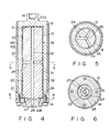
- a disk-like anode target 11 consisting of a heavy metal is integrally fixed to a rotating shaft portion 13 extending from one end of a cylindrical rotary structure 12 with a screw 14.
- a stationary shaft 15 is fitted in the cylindrical rotary structure 12.
- a disk-like flange 16 is fixed to the one opening portion of the rotary structure 12.
- An anode support portion 17 at the one end of the stationary shaft 15 is vaccum-tightly fitted in a glass vacuum envelope 18.
- a hydro-dynamic pressure sliding bearing portion 19 similar to the one disclosed in each official gazette mentioned above, is formed at the fitting portion between the cylindrical rotary structure 12 and the stationary shaft 15.
- spiral grooves 20 and 21 similar to those described in each official gazette mentioned above are formed in the outer surface and two end faces, of the stationary shaft 15, which serve as its sliding bearing surface.
- the sliding bearing surface of the rotary structure 12, which opposes the sliding bearing surface of the stationary shaft 15 is formed into a smooth surface or a surface in which spiral grooves or the like are formed as needed so that thrust and radial bearings are constituted.
- a ferro-magnetic cylinder 12a consisting of an iron material is fitted on an Mo member as the base member of the rotary structure 12
- a cylinder 12b consisting of a material having a low electrical resistance, e.g., copper, is fixed on the cylinder 12a.
- Mo or an Mo alloy (to be simply referred to as Mo hereinafter) is used as a base member for the rotary structure 12 and the stationary shaft 15.
- Thin reaction layers containing Mo as a base member metal for a bearing surface and at least Ga (to be simply referred as Mo-Ga reaction layers) 31 and 32 are respectively formed on the bearing surfaces. These Mo-Ga reaction layers 31 and 32 are formed on the surfaces of the base members in advance to have thicknesses of 1 ⁇ m to 100 ⁇ m. Examples of formation of such layers will be described later.
- a lubricant storage chamber 22 is formed in the stationary shaft 15 by forming a through hole in its central portion in the axial direction.
- the lubricant storage chamber 22 also serves as a circulation path for a lubricant.
- One end 22a of the lubricant storage chamber 22 is opened in an end face, of the outer surface of the stationary shaft 15, which has the spiral grooves 20.
- the lubricant storage chamber 22 is communicated with a gap of the thrust bearing.
- an intermediate portion of the outer surface of the stationary shaft 15 is slightly tapered to form a small-diameter portion 23, and three radial paths 24 extending from the lubricant storage chamber 22 are formed at angular intervals of 120° to be symmetrical about the axis.
- the lubricant paths 24 are communicated with a low-pressure space between the cylindrical rotary structure 12 and the small-diameter portion 23.
- the lubricant in the low-pressure space is maintained at a pressure lower than that of the gaps of the thrust and radial bearings.
- the other end 22b of the central lubricant storage chamber 22 is sealed by a plug 25 consisting of the same Mo material as that for the stationary shaft 15.
- a circumferential cavity 26 between a small diameter portion of the stationary shaft 15 and the rotary structure 12 is formed near the plug 25.
- Three radial paths 27 extending from the central lubricant storage chamber 22 to the circumferential cavity 26 are formed at angular intervals of 120° to be symmetrical about the axis.
- the lubricant storage chamber 22 is communicated with the circumferential cavity 26 through the radial paths 27 and the cavity 26 is also communicated with the gap of the thrust bearing between of the stationary shaft 15 the stepped face and the stepped inner face of the rotary structure 12.
- a gap g , and the spiral grooves 20 and 21 of the bearings, the paths 24 and the lubricant storage chamber 22 communicating therewith are filled with a liquid metal lubricant (not shown), as described above. Owing to the presence of the lubricant storage chamber 22, a sufficient amount of liquid metal lubricant for a long-term operation is supplied into the gaps of the bearings, when an amount of the lubricant is decreased in the gaps of the bearings, thus maintaining a required operation of the hydro-dynamic pressure type sliding bearing.
- the end portion of the stationary shaft 15 is integrally brazed to the anode support portion 17 consisting of an iron material.
- a stator 40 having an electromagnetic coil is arranged outside the vacuum envelope as to oppose the rotary structure 12.
- a rotating magnetic field is generated by the stator 40 to rotate the rotary anode at a high speed in a direction indicated by P in Fig. 1.
- An electron beam emitted from a cathode (not shown) are impinged on the anode target 11 to irradiate X-rays. Most of the heat generated in the target 11 is dissipated by radiation, while part of the heat is transferred from the rotary structure 12 to the liquid metal lubricant and is dissipated through the stationary shaft 15.
- the Mo-Ga reaction layers 31 and 32 constituting the bearing surfaces have sufficiently high electrical and thermal conductivities as the rotary-anode type X-ray tube, they properly function as paths for anode currents and heat.
- the layers 31 and 32 exhibit sufficiently high mechanical strength, thus providing a rotary-anode type X-ray tube having stable bearing operation performance.
- spiral grooves 20 and 21 having herringbone patterns are formed in predetermined portions, of the base members of the rotary structure 12 and the stationary shaft 15 consisting of Mo, which serve as bearing surfaces. These Mo base members are then heated to 700°C in a vacuum to clean the bearing surfaces. In the same vacuum, the temperature of the base members is kept within the range of about 450 to 550°C, e.g., at 500°C, and the base members are dipped into a bath of Ga (including an alloy consisting of Ga as a main element, e.g., a Ga-In-Sn alloy). The base members are kept in the bath for a predetermined period of time and are cooled down.
- Ga including an alloy consisting of Ga as a main element, e.g., a Ga-In-Sn alloy
- Mo-Ga reaction layers 31 and 32 each consisting of a compound containing Mo, Ga, In, and Sn, are formed on the surfaces of the base members, thus obtaining bearing surfaces.
- Each of the layers 31 and 32 is diffused into the original surface of a corresponding base member to a depth of about 2.5 ⁇ m and is deposited on the surface to a thickness of about 4.5 ⁇ m and hence has a total thickness of about 7 ⁇ m.
- Fig. 7 shows the distribution of the contents of the metal components at the respective positions, in the direction of depth, of the surface portion of the bearing member manufactured in this manner.
- This graph shows the molar ratios approximately calculated from the contents obtained by EPMA analysis.
- the position of an alternate long and short dashed line A in Fig. 7 corresponds to the original surface of each Mo base member.
- a region constituted by a metallic compound mainly consisting of Ga and Mo as the base member material, which ranges from the position A to a dotted line B can be recognized.
- the thickness of the region from the position A to the position B is about 2.5 ⁇ m.
- the ratio of Ga to Mo is abruptly reversed near the position B, and a metal region consisting of only Mo extends inward from the position B.
- Ga in the bath is diffused in the Mo base member to form the Ga-Mo reaction layer from the original surface to the position B.
- a metallic compound layer consisting of Ga, In, Sn, and Mo can be recognized.
- the surface C is a flat surface obtained by removing a rough surface portion resulting from the above-mentioned reaction process from the uppermost surface by a thickness of about 2 ⁇ m by polishing. It is confirmed that the reaction layer on this surface portion has sufficiently high hardness as a sliding bearing surface. In this manner, the Mo-Ga reaction layer 31 (or 32) is formed from the surface C to the predetermined depth position B.
- the gap between the bearing surfaces of the rotary structure and the stationary shaft before the formation of reaction layers is set to be larger than a predetermined gap by the thickness of these reaction layers so that the predetermined gap can be formed between the bearing surfaces upon formation of the reaction layers.
- the low-melting metal, in the bath, which is used to form a reaction layer together with the base member metal may consists of only Ga or an alloy of Ga and another metal having a relatively low melting point.
- the reaction layer of each bearing surface hardly changes, and the bearing surface having high hardness is maintained.
- this oxide film can be very easily removed.
- a liquid lubricant consisting of Ga or a Ga alloy is filled between the bearing surfaces upon assembly of the bearing surfaces as a sliding bearing, stable direct contact can be ensured, with excellent wettability, between the bearing surfaces consisting of the Mo-Ga reaction layers and the liquid metal lubricant. Therefore, assembly is facilitated, and a satisfactory function as a dynamic pressure type sliding bearing can be obtained.
- an Mo-Ga reaction layer 31 or 32 having a relatively large thickness of about 50 ⁇ m is formed in the surface of the base member of a rotary structure or a stationary shaft by a method similar to that described above.
- the surface of this reaction layer is ground to have a predetermined diameter as a bearing surface, and at the same time, spiral grooves 20 or 21 are formed in the reaction layer by a mechanical process or chemical etching.
- an X-ray tube including a dynamic pressure system sliding bearing having desired high-precision spiral grooves and a desired gap between the bearing surfaces can be manufactured.
- At least a region from a surface portion C to a original base member surface A may be removed by polishing to expose a compound layer (corresponding to the region from the position A to the position B in Fig. 7) in which Ga is diffused in Mo, and spiral grooves may be formed in the exposed compound layer as a bearing surface.
- a compound layer corresponding to the region from the position A to the position B in Fig. 7
- spiral grooves may be formed in the exposed compound layer as a bearing surface.
- surface reaction layers are independently formed on the rotary structure and the stationary shaft in the form of parts.
- an X-ray tube can be manufactured in the following manner.
- the rotary structure and stationary shaft are manufactured and assembled in advance in such a manner that the gap between bearing surfaces is larger than that of the finished product.
- the gap between the bearing surfaces and a lubricant storage chamber are filled with a lubricant consisting of Ga or a Ga alloy. Thereafter, these components are heated at about 500°C in a vacuum for a predetermined period of time and are subsequently cooled down.
- Mo-Ga reaction layers are respectively formed on the bearing surfaces of the rotary structure and the stationary shaft, and the remaining Ga or Ga alloy lubricant is left in the gap between the bearing surfaces, which is reduced to a predetermined gap.
- the gap between the bearing surfaces and the lubricant storage chamber are replenished with a Ga or Ga alloy lubricant, as needed, thus completing an X-ray tube.
- each bearing surface may be constituted by W (including an alloy mainly consisting of W), niobium (Nb) (including an alloy mainly consisting of Nb), or tantalum (Ta) (including an alloy mainly consisting of Ta).
- W including an alloy mainly consisting of W
- Nb including an alloy mainly consisting of Nb
- tantalum including an alloy mainly consisting of Ta
- another metal such as iron or stainless steel, or in an example useful for the understanding of the invention
- a ceramic material may be used as a bearing constituent element
- a bearing surface base member may be formed by coating a thin layer consisting of a refractory metal, such as the one described above, on a portion, of the bearing constituent element, which serves as a bearing surface.
- the thicknesses of reaction layers consisting of these base member metals and Ga and formed on the surface portion thereof must be set to be 1 ⁇ m or more in order to facilitate control of the formation of the reaction layers.
- the base member of a bearing surface may be constituted by a ceramic material such as titanium nitride, zirconium nitride, or a ceramic material such as vanadium carbide, titanium carbide, or niobium carbide.
- the base member may be constituted by a carbonitride ceramic material such as vanadium carbonitride or titanium carbonitride.
- a bearing surface base member may be formed by coating a layer consisting of a nitride, a carbide, or a carbonitride ceramic material on a surface portion of another metal. If a bearing surface base member consisting of a nitride, a carbide, or a carbonitride ceramic material is to be formed, the thickness of a reaction layer consisting of the bearing surface base member and Ga or Bi is preferably set to be 1 ⁇ m or more in order to facilitate control of formation of the reaction layers. More specifically, as shown in Fig.
- the CVD method is employed to deposit a titanium nitride ceramic layer 33 having a thickness of several ⁇ m on a bearing surface portion, of a stationary shaft 15, in which spiral grooves 20 and 21 are formed in advance.
- a reaction layer 34 consisting of titanium nitride and Ga or Bi may be formed on the resultant surface to a thickness of about 2 ⁇ m, thereby forming a bearing surface.
- reaction layer consisting of the bearing surface base member and Ga or Bi has electrical conductivity
- the layer can also be used as part of a path of an anode current for the X-ray tube.
- the present invention is not limited to a lubricant mainly consisting of Ga, e.g., a Ga, Ga-In, or Ga-In-Sn lubricant.
- a lubricant consisting of an alloy containing a relatively large amount of bismuth (Bi), e.g., a Bi-In-Pb-Sn alloy, or a lubricant consisting of an alloy containing a relatively large amount of In, e.g., an In-Bi or In-Bi-Sn alloy may be used. Since these materials have melting points higher than the room temperature, it is preferable that a metal lubricant consisting of such a material be preheated to a temperature higher than its melting point before an anode target is rotated.
- a thin reaction layer containing a bearing surface base member and at least Ga is formed on a surface portion of a sliding bearing surface, excellent wettability between this bearing surface and a liquid metal lubricant can be ensured, thereby maintaining a stable operation of a dynamic pressure type sliding bearing.
- a rotary-anode type X-ray tube which allows easy assembly of a bearing and has a highly reliable bearing function.
Landscapes
- Engineering & Computer Science (AREA)
- General Engineering & Computer Science (AREA)
- Mechanical Engineering (AREA)
- Sliding-Contact Bearings (AREA)
Claims (2)
- Tube à rayons X à anode tournante, comprenant :une cible anodique (11),une structure rotative (12) ayant un axe central de rotation et à laquelle est fixée la cible anodique (11),une structure fixe (15) disposée coaxialement à la structure rotative (12) et destinée à maintenir la structure rotative (12) afin qu'elle puisse tourner, etun palier hydrodynamique (19) formé entre la structure rotative (12) et la structure fixe (15), ayant des gorges spiralées et un espace dans lequel est appliqué un lubrifiant métallique, le lubrifiant métallique étant à l'état liquide pendant la rotation de la structure rotative (12),caractérisé en ce quele lubrifiant métallique est choisi dans le groupe constitué par le gallium, les alliages de gallium, les alliages d'indium et les alliages de bismuth,l'une au moins des structures rotative et fixe (12, 15) a un organe de base ayant une couche superficielle (31, 32) formée de manière que la couche superficielle soit au contact du lubrifiant métallique placé dans ledit espace (g), etle matériau de l'organe de base ou de chaque organe de base est choisi dans le groupe constitué par le molybdène, le tungstène, le niobium, le tantale, le fer, un alliage de molybdène, un alliage constitué essentiellement de tungstène, un alliage constitué essentiellement de niobium, un alliage constitué essentiellement de tantale, et un acier inoxydable, la couche ou chaque couche de surface étant formée d'un alliage du métal du lubrifiant et du métal de l'organe de base de manière que l'alliage contienne au moins un élément du groupe formé par le gallium, l'indium, le bismuth et l'étain, et la couche ou chaque couche de surface n'a pas une épaisseur inférieure à 1 µm.
- Tube à rayons X à anode tournante selon la revendication 1, caractérisé en ce que les gorges spiralées sont formées au moins dans une couche de surface.
Applications Claiming Priority (2)
| Application Number | Priority Date | Filing Date | Title |
|---|---|---|---|
| JP279350/90 | 1990-10-19 | ||
| JP27935090 | 1990-10-19 |
Publications (2)
| Publication Number | Publication Date |
|---|---|
| EP0482386A1 EP0482386A1 (fr) | 1992-04-29 |
| EP0482386B1 true EP0482386B1 (fr) | 1996-12-11 |
Family
ID=17609949
Family Applications (1)
| Application Number | Title | Priority Date | Filing Date |
|---|---|---|---|
| EP91116670A Expired - Lifetime EP0482386B1 (fr) | 1990-10-19 | 1991-09-30 | Tube à rayons X avec anode tournante |
Country Status (6)
| Country | Link |
|---|---|
| US (1) | US5181235A (fr) |
| EP (1) | EP0482386B1 (fr) |
| KR (1) | KR940009195B1 (fr) |
| CN (1) | CN1024065C (fr) |
| CA (1) | CA2052472C (fr) |
| DE (1) | DE69123554T2 (fr) |
Families Citing this family (27)
| Publication number | Priority date | Publication date | Assignee | Title |
|---|---|---|---|---|
| CN1039561C (zh) * | 1992-04-08 | 1998-08-19 | 株式会社东芝 | 旋转阳极x射线管 |
| US5806856A (en) * | 1992-08-27 | 1998-09-15 | Ferrofluidics Corporation | On-site fillable liquid magnetic seal |
| DE19523163A1 (de) * | 1994-07-12 | 1996-01-18 | Siemens Ag | Gleitlagerteil für ein Flüssigmetallgleitlager |
| DE19510067A1 (de) * | 1995-03-20 | 1996-10-02 | Siemens Ag | Gleitlager mit einem mit Flüssigmetall gefüllten Lagerspalt |
| DE19605085C2 (de) * | 1996-02-12 | 1999-07-29 | Siemens Ag | Flüssigmetall-Gleitlager mit einer Einfüllöffnung |
| DE19612693A1 (de) * | 1996-03-29 | 1997-09-04 | Siemens Ag | Gleitlager für eine Drehanode einer Röntgenröhre |
| JP2001325908A (ja) * | 2000-03-09 | 2001-11-22 | Toshiba Corp | 回転陽極型x線管 |
| JP4338359B2 (ja) | 2002-06-11 | 2009-10-07 | 日本電産株式会社 | 動圧軸受装置 |
| DE10241515B4 (de) * | 2002-09-07 | 2005-04-28 | Rexroth Indramat Gmbh | Verbindungselement zur Befestigung eines Elektromotors |
| US7260181B2 (en) * | 2003-05-30 | 2007-08-21 | Koninklijke Philips Electronics, N.V. | Enhanced electron backscattering in x-ray tubes |
| GB0507681D0 (en) * | 2005-04-15 | 2005-05-25 | Westwind Air Bearings Ltd | Gas bearing spindles |
| JP2007016884A (ja) * | 2005-07-07 | 2007-01-25 | Ge Medical Systems Global Technology Co Llc | 軸受機構およびx線管 |
| JP2007107622A (ja) * | 2005-10-14 | 2007-04-26 | Matsushita Electric Ind Co Ltd | 動圧軸受装置およびそれを用いたスピンドルモータ |
| WO2007083491A1 (fr) * | 2006-01-19 | 2007-07-26 | Ntn Corporation | Élément d'arbre pour un dispositif de palier à pression dynamique |
| US8363787B2 (en) * | 2009-03-25 | 2013-01-29 | General Electric Company | Interface for liquid metal bearing and method of making same |
| US7933382B2 (en) * | 2009-03-25 | 2011-04-26 | General Electric Company | Interface for liquid metal bearing and method of making same |
| CN102194632A (zh) * | 2010-03-03 | 2011-09-21 | 通用电气公司 | 用于液态金属轴承的界面及其制造方法 |
| US8300770B2 (en) | 2010-07-13 | 2012-10-30 | Varian Medical Systems, Inc. | Liquid metal containment in an x-ray tube |
| US9263224B2 (en) | 2013-05-31 | 2016-02-16 | General Electric Company | Liquid bearing assembly and method of constructing same |
| RU2677754C2 (ru) * | 2014-05-21 | 2019-01-21 | Конинклейке Филипс Н.В. | Гидродинамический подшипник, рентгеновская трубка, рентгеновская система и способ изготовления гидродинамического подшипника |
| US9972472B2 (en) * | 2014-11-10 | 2018-05-15 | General Electric Company | Welded spiral groove bearing assembly |
| US10032598B2 (en) | 2016-07-26 | 2018-07-24 | Neil Dee Olsen | X-ray systems and methods including X-ray anodes |
| US10438768B2 (en) | 2016-07-26 | 2019-10-08 | Neil Dee Olsen | X-ray systems and methods including X-ray anodes with gradient profiles |
| US10490385B2 (en) | 2016-07-26 | 2019-11-26 | Neil Dee Olsen | X-ray systems and methods including X-ray anodes |
| FR3062950A1 (fr) * | 2017-02-15 | 2018-08-17 | Acerde | Dispositif rotatif de production de rayons x, appareil comprenant un tel dispositif et procede de traitement d'un tel dispositif |
| US11020067B1 (en) * | 2020-02-12 | 2021-06-01 | GE Precision Healthcare LLC | Hydrodynamic bearing system and method for manufacturing the hydrodynamic bearing system |
| CN113153907B (zh) * | 2021-05-27 | 2024-09-20 | 中国工程物理研究院机械制造工艺研究所 | 一种液态金属轴承及真空电机 |
Family Cites Families (8)
| Publication number | Priority date | Publication date | Assignee | Title |
|---|---|---|---|---|
| US3720853A (en) * | 1971-03-02 | 1973-03-13 | Picker Corp | Bearing structure for x-ray tube with rotating anode |
| NL7713634A (nl) * | 1977-12-09 | 1979-06-12 | Philips Nv | Roentgenbuis met draaianode. |
| NL8303422A (nl) * | 1983-10-06 | 1985-05-01 | Philips Nv | Roentgenbuis met draaianode. |
| NL8303832A (nl) * | 1983-11-08 | 1985-06-03 | Philips Nv | Roentgenbuis met spiraalgroeflager. |
| NL8601414A (nl) * | 1986-06-02 | 1988-01-04 | Philips Nv | Roentgenbuis met een draaianode. |
| DE3900729A1 (de) * | 1989-01-12 | 1990-07-19 | Philips Patentverwaltung | Drehanoden-roentgenroehre mit einem gleitlager, insbesondere einem spiralrillenlager |
| US4956858A (en) * | 1989-02-21 | 1990-09-11 | General Electric Company | Method of producing lubricated bearings |
| US4914684A (en) * | 1989-03-31 | 1990-04-03 | General Electric Company | Titanium carbide coating of bearing components |
-
1991
- 1991-07-26 CN CN91105217A patent/CN1024065C/zh not_active Expired - Fee Related
- 1991-07-31 KR KR1019910013393A patent/KR940009195B1/ko not_active Expired - Fee Related
- 1991-09-27 US US07/766,126 patent/US5181235A/en not_active Expired - Lifetime
- 1991-09-30 EP EP91116670A patent/EP0482386B1/fr not_active Expired - Lifetime
- 1991-09-30 DE DE69123554T patent/DE69123554T2/de not_active Expired - Fee Related
- 1991-09-30 CA CA002052472A patent/CA2052472C/fr not_active Expired - Fee Related
Also Published As
| Publication number | Publication date |
|---|---|
| CN1060738A (zh) | 1992-04-29 |
| CN1024065C (zh) | 1994-03-16 |
| DE69123554D1 (de) | 1997-01-23 |
| EP0482386A1 (fr) | 1992-04-29 |
| DE69123554T2 (de) | 1997-04-30 |
| CA2052472C (fr) | 1997-09-09 |
| CA2052472A1 (fr) | 1992-04-20 |
| KR920008824A (ko) | 1992-05-28 |
| KR940009195B1 (ko) | 1994-10-01 |
| US5181235A (en) | 1993-01-19 |
Similar Documents
| Publication | Publication Date | Title |
|---|---|---|
| US5181235A (en) | Rotary-anode type x-ray tube | |
| US5204890A (en) | Rotary anode type x-ray tube | |
| US8240923B2 (en) | X-ray tube rotating anode assembly bearing | |
| JP2960085B2 (ja) | 回転陽極x線管 | |
| KR970002680B1 (ko) | 회전양극형 x선관 | |
| EP0479195B2 (fr) | Tube à rayons à anode tournante | |
| EP1124250B1 (fr) | Palier pour tube à rayons X | |
| JP3139873B2 (ja) | 回転陽極型x線管 | |
| US6582531B2 (en) | X-ray tube and method of manufacture | |
| US3720853A (en) | Bearing structure for x-ray tube with rotating anode | |
| JP2856531B2 (ja) | 回転陽極型x線管 | |
| JP2930255B2 (ja) | 回転陽極型x線管 | |
| JP4112829B2 (ja) | 回転陽極型x線管 | |
| JP3017859B2 (ja) | 回転陽極型x線管およびその製造方法 | |
| JP2989056B2 (ja) | 回転陽極型x線管 | |
| CN1030807C (zh) | 旋转阳极型x射线管 | |
| JP4467740B2 (ja) | 回転陽極型x線管 | |
| JP3124023B2 (ja) | 回転陽極型x線管の製造方法 | |
| JP3032275B2 (ja) | 回転陽極型x線管 | |
| JP2937574B2 (ja) | 回転陽極型x線管 | |
| JP2886334B2 (ja) | 回転陽極型x線管 | |
| JP3045906B2 (ja) | 回転陽極型x線管 | |
| JP2001312985A (ja) | 回転陽極型x線管 |
Legal Events
| Date | Code | Title | Description |
|---|---|---|---|
| PUAI | Public reference made under article 153(3) epc to a published international application that has entered the european phase |
Free format text: ORIGINAL CODE: 0009012 |
|
| 17P | Request for examination filed |
Effective date: 19911025 |
|
| AK | Designated contracting states |
Kind code of ref document: A1 Designated state(s): DE FR GB IT |
|
| 17Q | First examination report despatched |
Effective date: 19940725 |
|
| GRAH | Despatch of communication of intention to grant a patent |
Free format text: ORIGINAL CODE: EPIDOS IGRA |
|
| GRAH | Despatch of communication of intention to grant a patent |
Free format text: ORIGINAL CODE: EPIDOS IGRA |
|
| RBV | Designated contracting states (corrected) |
Designated state(s): DE FR GB |
|
| GRAA | (expected) grant |
Free format text: ORIGINAL CODE: 0009210 |
|
| AK | Designated contracting states |
Kind code of ref document: B1 Designated state(s): DE FR GB |
|
| REF | Corresponds to: |
Ref document number: 69123554 Country of ref document: DE Date of ref document: 19970123 |
|
| ET | Fr: translation filed | ||
| ET | Fr: translation filed |
Free format text: CORRECTIONS |
|
| PLBE | No opposition filed within time limit |
Free format text: ORIGINAL CODE: 0009261 |
|
| STAA | Information on the status of an ep patent application or granted ep patent |
Free format text: STATUS: NO OPPOSITION FILED WITHIN TIME LIMIT |
|
| 26N | No opposition filed | ||
| REG | Reference to a national code |
Ref country code: GB Ref legal event code: 746 Effective date: 19980915 |
|
| REG | Reference to a national code |
Ref country code: FR Ref legal event code: D6 |
|
| REG | Reference to a national code |
Ref country code: GB Ref legal event code: IF02 |
|
| PGFP | Annual fee paid to national office [announced via postgrant information from national office to epo] |
Ref country code: GB Payment date: 20020925 Year of fee payment: 12 |
|
| PG25 | Lapsed in a contracting state [announced via postgrant information from national office to epo] |
Ref country code: GB Free format text: LAPSE BECAUSE OF NON-PAYMENT OF DUE FEES Effective date: 20030930 |
|
| GBPC | Gb: european patent ceased through non-payment of renewal fee |
Effective date: 20030930 |
|
| PGFP | Annual fee paid to national office [announced via postgrant information from national office to epo] |
Ref country code: FR Payment date: 20080915 Year of fee payment: 18 |
|
| PGFP | Annual fee paid to national office [announced via postgrant information from national office to epo] |
Ref country code: DE Payment date: 20081014 Year of fee payment: 18 |
|
| REG | Reference to a national code |
Ref country code: FR Ref legal event code: ST Effective date: 20100531 |
|
| PG25 | Lapsed in a contracting state [announced via postgrant information from national office to epo] |
Ref country code: DE Free format text: LAPSE BECAUSE OF NON-PAYMENT OF DUE FEES Effective date: 20100401 Ref country code: FR Free format text: LAPSE BECAUSE OF NON-PAYMENT OF DUE FEES Effective date: 20090930 |