EP0482441A2 - Commutateur de proximité avec compensation d'instabilités de sensibilité dues à la température - Google Patents
Commutateur de proximité avec compensation d'instabilités de sensibilité dues à la température Download PDFInfo
- Publication number
- EP0482441A2 EP0482441A2 EP91117318A EP91117318A EP0482441A2 EP 0482441 A2 EP0482441 A2 EP 0482441A2 EP 91117318 A EP91117318 A EP 91117318A EP 91117318 A EP91117318 A EP 91117318A EP 0482441 A2 EP0482441 A2 EP 0482441A2
- Authority
- EP
- European Patent Office
- Prior art keywords
- frequency
- connection point
- proximity switch
- transmission
- oscillator
- Prior art date
- Legal status (The legal status is an assumption and is not a legal conclusion. Google has not performed a legal analysis and makes no representation as to the accuracy of the status listed.)
- Granted
Links
Images
Classifications
-
- H—ELECTRICITY
- H03—ELECTRONIC CIRCUITRY
- H03K—PULSE TECHNIQUE
- H03K17/00—Electronic switching or gating, i.e. not by contact-making and –breaking
- H03K17/94—Electronic switching or gating, i.e. not by contact-making and –breaking characterised by the way in which the control signals are generated
- H03K17/945—Proximity switches
- H03K17/95—Proximity switches using a magnetic detector
- H03K17/952—Proximity switches using a magnetic detector using inductive coils
- H03K17/9525—Proximity switches using a magnetic detector using inductive coils controlled by an oscillatory signal
Definitions
- the invention relates to a proximity switch with a transmission oscillator and with a converter excited by the transmission frequency of the transmission oscillator.
- the transmit oscillators are usually operated in proximity switches with a constant transmit frequency.
- the resonance frequency of the transducer is temperature-dependent, there are correspondingly large deviations of the transmission or reception frequency from the instantaneous resonance frequency of the transducer due to temperature fluctuations, which result in losses in the sensitivity of the proximity switch.
- the task is to produce a proximity switch, the sensitivity of which is easily improved in the event of temperature fluctuations.
- This is achieved in that means are provided with which the transmission frequency of the transmission oscillator can track the temperature-dependent resonance frequency of the converter.
- a particularly simple and expedient embodiment exists when a thermistor is used as the means, with which a temperature-linear influencing of an electrical control variable can be achieved, with which the transmission frequency of the transmission oscillator can be controlled.
- the thermistor is connected to ground with its one connection point and its other connection point is connected to a voltage source via a first ohmic resistor, the connection point between the thermistor and the first ohmic resistor second ohmic resistor is connected, the other connection point of which is connected to ground, and that a third ohmic resistor is connected to the connection point, the other connection point of which is electrically connected to an input of the transmission oscillator. Further inputs of the transmission oscillator are electrically connected to components which are used to tune the frequency of the transmission oscillator.
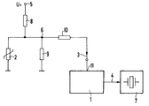
- the figure shows a transmission oscillator 1 of a proximity switch.
- the transmission oscillator 1 which can be designed, for example, as a customer-specific circuit, generates a specific transmission frequency 4 via a resistance circuit with a thermistor 2 as a function of an input current 3.
- the thermistor 2 connects the transmission oscillator 1 to a temperature-dependent voltage source.
- the resistor circuit with the ohmic resistors 8 and 9 serves to linearize the characteristic of the thermistor 2.
- the thermistor 2 is connected via the ohmic resistor 8 to a voltage source 5.
- the ohmic resistor 9 is parallel to the thermistor 2.
- the ohmic resistor 10 is also connected to the connection point 6 between the thermistor 2 and the ohmic resistor 8, the other connection point of which lies at the input 11 of the transmission oscillator 1.
- the transmission frequency 4 of the transmission oscillator 1 is controlled via the input 11 by means of the input current 3.
- the control current 3 is adapted to temperature fluctuations by means of the thermistor 2 in conjunction with the resistor circuit in the following way:
- the thermistor 2 forms, together with the resistor 8, a voltage divider for the voltage source 5.
- the additional resistor 9 linearizes the curved characteristic of the thermistor 2.
- a temperature-dependent voltage is present at connection point 6, which voltage decreases as the temperature rises due to the behavior of thermistor 2.
- the coupling from the connection point 6 to the input 11 of the transmission oscillator 1 via the resistor 10 causes a voltage / current conversion.
- a decrease in voltage at the connection point 6 with increasing temperature results in a lower current 3, which causes a reduction in the transmission frequency 4 in the transmission oscillator 1.
- the transmission frequency 4 tracks the temperature-dependent resonance frequency of the transducer 7 in a suitable manner.
Landscapes
- Electronic Switches (AREA)
- Switches That Are Operated By Magnetic Or Electric Fields (AREA)
- Inductance-Capacitance Distribution Constants And Capacitance-Resistance Oscillators (AREA)
Priority Applications (1)
| Application Number | Priority Date | Filing Date | Title |
|---|---|---|---|
| AT91117318T ATE100255T1 (de) | 1990-10-22 | 1991-10-10 | Naeherungsschalter mit kompensation temperaturbedingter empfindlichkeitsschwankungen. |
Applications Claiming Priority (2)
| Application Number | Priority Date | Filing Date | Title |
|---|---|---|---|
| DE9014618U DE9014618U1 (de) | 1990-10-22 | 1990-10-22 | Näherungsschalter mit Kompensation temperaturbedingter Empfindlichkeitsschwankungen |
| DE9014618U | 1990-10-22 |
Publications (3)
| Publication Number | Publication Date |
|---|---|
| EP0482441A2 true EP0482441A2 (fr) | 1992-04-29 |
| EP0482441A3 EP0482441A3 (en) | 1992-05-20 |
| EP0482441B1 EP0482441B1 (fr) | 1994-01-12 |
Family
ID=6858624
Family Applications (1)
| Application Number | Title | Priority Date | Filing Date |
|---|---|---|---|
| EP91117318A Expired - Lifetime EP0482441B1 (fr) | 1990-10-22 | 1991-10-10 | Commutateur de proximité avec compensation d'instabilités de sensibilité dues à la température |
Country Status (4)
| Country | Link |
|---|---|
| EP (1) | EP0482441B1 (fr) |
| JP (1) | JPH04265014A (fr) |
| AT (1) | ATE100255T1 (fr) |
| DE (2) | DE9014618U1 (fr) |
Families Citing this family (1)
| Publication number | Priority date | Publication date | Assignee | Title |
|---|---|---|---|---|
| DE102004006901C5 (de) * | 2004-02-12 | 2013-01-31 | Werner Turck Gmbh & Co. Kg | Näherungsschalter |
Family Cites Families (2)
| Publication number | Priority date | Publication date | Assignee | Title |
|---|---|---|---|---|
| US3707671A (en) * | 1970-05-01 | 1972-12-26 | Robert S Morrow | Inductive vibration pickup apparatus |
| DE3643589A1 (de) * | 1986-12-19 | 1987-05-27 | Siemens Ag | Schaltungsanordnung zum vermindern des temperaturkoeffizienten bei induktiven naeherungsschaltern |
-
1990
- 1990-10-22 DE DE9014618U patent/DE9014618U1/de not_active Expired - Lifetime
-
1991
- 1991-10-10 AT AT91117318T patent/ATE100255T1/de not_active IP Right Cessation
- 1991-10-10 DE DE91117318T patent/DE59100851D1/de not_active Expired - Fee Related
- 1991-10-10 EP EP91117318A patent/EP0482441B1/fr not_active Expired - Lifetime
- 1991-10-18 JP JP3298144A patent/JPH04265014A/ja not_active Withdrawn
Also Published As
| Publication number | Publication date |
|---|---|
| EP0482441A3 (en) | 1992-05-20 |
| DE59100851D1 (de) | 1994-02-24 |
| DE9014618U1 (de) | 1991-01-03 |
| EP0482441B1 (fr) | 1994-01-12 |
| JPH04265014A (ja) | 1992-09-21 |
| ATE100255T1 (de) | 1994-01-15 |
Similar Documents
| Publication | Publication Date | Title |
|---|---|---|
| DE3321531C2 (fr) | ||
| EP0348701B1 (fr) | Appareil pour mesurer la distance | |
| DE68925902T2 (de) | Stromquelle für eine wechselnde last mit einer induktiven last | |
| DE2453153C2 (de) | Spannungsgesteuerter Oszillator | |
| DE2600890B2 (de) | Ultraschallgenerator mit einem Ultraschallwandler | |
| DE3934007A1 (de) | Zweidraht-fernmesseinrichtung | |
| EP0626595B1 (fr) | Capteur | |
| DE60001416T2 (de) | Kontrollvorrichtung für ein zahnärztliches ultraschallhandstück | |
| EP0813306A1 (fr) | Oscillateur stabilisé en température et commutateur de proximité en faisant usage | |
| DE69303204T2 (de) | Tragbarer, batterieloser Frequenzteiler mit magnetischer und elektrischer Kupplung | |
| DE3900802C2 (fr) | ||
| DE2916540C2 (de) | Elektrische Schaltungsanordnung zur Ansteuerung eines piezoelektrischen Wandlers | |
| DE2814467A1 (de) | Ultraschall-oszillatorsystem | |
| DE69534008T2 (de) | Eine oszillator- und senderanordnung | |
| DE3606586A1 (de) | Annaeherungsschalter | |
| DE3887009T2 (de) | Elektronisches Netzwerk zur Nachbildung von Blindwiderständen. | |
| DE19828622A1 (de) | Breitbandoszillator mit automatischer Vorspannungssteuerung | |
| EP0482441A2 (fr) | Commutateur de proximité avec compensation d'instabilités de sensibilité dues à la température | |
| DE2039695C3 (de) | Amplitudengeregelter Transistoroszillatoror | |
| DE69817897T2 (de) | Phasenregelkreis | |
| DE2929646C2 (de) | Ultraschallgenerator | |
| EP0343403B1 (fr) | Circuit pour l'auto-excitation d'un oscillateur mécanique jusqu'à sa fréquence de résonance propre | |
| DE3705932C1 (de) | Verstaerker | |
| DE10328113A1 (de) | Vorrichtung zum Betreiben einer schwingfähigen Einheit eines Vibrationsresonators | |
| DE102020004382B4 (de) | Elektrische Schaltung für einen induktiv betriebenen Näherungsschalter |
Legal Events
| Date | Code | Title | Description |
|---|---|---|---|
| PUAI | Public reference made under article 153(3) epc to a published international application that has entered the european phase |
Free format text: ORIGINAL CODE: 0009012 |
|
| PUAL | Search report despatched |
Free format text: ORIGINAL CODE: 0009013 |
|
| AK | Designated contracting states |
Kind code of ref document: A2 Designated state(s): AT CH DE FR GB IT LI |
|
| AK | Designated contracting states |
Kind code of ref document: A3 Designated state(s): AT CH DE FR GB IT LI |
|
| 17P | Request for examination filed |
Effective date: 19920609 |
|
| 17Q | First examination report despatched |
Effective date: 19920819 |
|
| GRAA | (expected) grant |
Free format text: ORIGINAL CODE: 0009210 |
|
| AK | Designated contracting states |
Kind code of ref document: B1 Designated state(s): AT CH DE FR GB IT LI |
|
| REF | Corresponds to: |
Ref document number: 100255 Country of ref document: AT Date of ref document: 19940115 Kind code of ref document: T |
|
| REF | Corresponds to: |
Ref document number: 59100851 Country of ref document: DE Date of ref document: 19940224 |
|
| ITF | It: translation for a ep patent filed | ||
| ET | Fr: translation filed | ||
| GBT | Gb: translation of ep patent filed (gb section 77(6)(a)/1977) |
Effective date: 19940325 |
|
| PLBE | No opposition filed within time limit |
Free format text: ORIGINAL CODE: 0009261 |
|
| STAA | Information on the status of an ep patent application or granted ep patent |
Free format text: STATUS: NO OPPOSITION FILED WITHIN TIME LIMIT |
|
| 26N | No opposition filed | ||
| PGFP | Annual fee paid to national office [announced via postgrant information from national office to epo] |
Ref country code: AT Payment date: 19950920 Year of fee payment: 5 |
|
| PG25 | Lapsed in a contracting state [announced via postgrant information from national office to epo] |
Ref country code: AT Effective date: 19961010 |
|
| REG | Reference to a national code |
Ref country code: GB Ref legal event code: IF02 |
|
| PG25 | Lapsed in a contracting state [announced via postgrant information from national office to epo] |
Ref country code: IT Free format text: LAPSE BECAUSE OF NON-PAYMENT OF DUE FEES;WARNING: LAPSES OF ITALIAN PATENTS WITH EFFECTIVE DATE BEFORE 2007 MAY HAVE OCCURRED AT ANY TIME BEFORE 2007. THE CORRECT EFFECTIVE DATE MAY BE DIFFERENT FROM THE ONE RECORDED. Effective date: 20051010 |
|
| PGFP | Annual fee paid to national office [announced via postgrant information from national office to epo] |
Ref country code: GB Payment date: 20051013 Year of fee payment: 15 |
|
| PGFP | Annual fee paid to national office [announced via postgrant information from national office to epo] |
Ref country code: FR Payment date: 20051025 Year of fee payment: 15 |
|
| PGFP | Annual fee paid to national office [announced via postgrant information from national office to epo] |
Ref country code: DE Payment date: 20051219 Year of fee payment: 15 |
|
| PGFP | Annual fee paid to national office [announced via postgrant information from national office to epo] |
Ref country code: CH Payment date: 20060105 Year of fee payment: 15 |
|
| PG25 | Lapsed in a contracting state [announced via postgrant information from national office to epo] |
Ref country code: LI Free format text: LAPSE BECAUSE OF NON-PAYMENT OF DUE FEES Effective date: 20061031 Ref country code: CH Free format text: LAPSE BECAUSE OF NON-PAYMENT OF DUE FEES Effective date: 20061031 |
|
| PG25 | Lapsed in a contracting state [announced via postgrant information from national office to epo] |
Ref country code: DE Free format text: LAPSE BECAUSE OF NON-PAYMENT OF DUE FEES Effective date: 20070501 |
|
| REG | Reference to a national code |
Ref country code: CH Ref legal event code: PL |
|
| GBPC | Gb: european patent ceased through non-payment of renewal fee |
Effective date: 20061010 |
|
| REG | Reference to a national code |
Ref country code: FR Ref legal event code: ST Effective date: 20070629 |
|
| PG25 | Lapsed in a contracting state [announced via postgrant information from national office to epo] |
Ref country code: GB Free format text: LAPSE BECAUSE OF NON-PAYMENT OF DUE FEES Effective date: 20061010 |
|
| PG25 | Lapsed in a contracting state [announced via postgrant information from national office to epo] |
Ref country code: FR Free format text: LAPSE BECAUSE OF NON-PAYMENT OF DUE FEES Effective date: 20061031 |