EP0482645A2 - Optical recording system - Google Patents
Optical recording system Download PDFInfo
- Publication number
- EP0482645A2 EP0482645A2 EP91118170A EP91118170A EP0482645A2 EP 0482645 A2 EP0482645 A2 EP 0482645A2 EP 91118170 A EP91118170 A EP 91118170A EP 91118170 A EP91118170 A EP 91118170A EP 0482645 A2 EP0482645 A2 EP 0482645A2
- Authority
- EP
- European Patent Office
- Prior art keywords
- disk
- area
- written
- program
- recorded
- Prior art date
- Legal status (The legal status is an assumption and is not a legal conclusion. Google has not performed a legal analysis and makes no representation as to the accuracy of the status listed.)
- Granted
Links
Images


Classifications
-
- G—PHYSICS
- G11—INFORMATION STORAGE
- G11B—INFORMATION STORAGE BASED ON RELATIVE MOVEMENT BETWEEN RECORD CARRIER AND TRANSDUCER
- G11B27/00—Editing; Indexing; Addressing; Timing or synchronising; Monitoring; Measuring tape travel
- G11B27/10—Indexing; Addressing; Timing or synchronising; Measuring tape travel
- G11B27/19—Indexing; Addressing; Timing or synchronising; Measuring tape travel by using information detectable on the record carrier
- G11B27/28—Indexing; Addressing; Timing or synchronising; Measuring tape travel by using information detectable on the record carrier by using information signals recorded by the same method as the main recording
- G11B27/32—Indexing; Addressing; Timing or synchronising; Measuring tape travel by using information detectable on the record carrier by using information signals recorded by the same method as the main recording on separate auxiliary tracks of the same or an auxiliary record carrier
- G11B27/327—Table of contents
- G11B27/329—Table of contents on a disc [VTOC]
-
- G—PHYSICS
- G11—INFORMATION STORAGE
- G11B—INFORMATION STORAGE BASED ON RELATIVE MOVEMENT BETWEEN RECORD CARRIER AND TRANSDUCER
- G11B19/00—Driving, starting, stopping record carriers not specifically of filamentary or web form, or of supports therefor; Control thereof; Control of operating function ; Driving both disc and head
- G11B19/02—Control of operating function, e.g. switching from recording to reproducing
-
- G—PHYSICS
- G11—INFORMATION STORAGE
- G11B—INFORMATION STORAGE BASED ON RELATIVE MOVEMENT BETWEEN RECORD CARRIER AND TRANSDUCER
- G11B27/00—Editing; Indexing; Addressing; Timing or synchronising; Monitoring; Measuring tape travel
- G11B27/02—Editing, e.g. varying the order of information signals recorded on, or reproduced from, record carriers
- G11B27/031—Electronic editing of digitised analogue information signals, e.g. audio or video signals
- G11B27/034—Electronic editing of digitised analogue information signals, e.g. audio or video signals on discs
-
- G—PHYSICS
- G11—INFORMATION STORAGE
- G11B—INFORMATION STORAGE BASED ON RELATIVE MOVEMENT BETWEEN RECORD CARRIER AND TRANSDUCER
- G11B27/00—Editing; Indexing; Addressing; Timing or synchronising; Monitoring; Measuring tape travel
- G11B27/10—Indexing; Addressing; Timing or synchronising; Measuring tape travel
- G11B27/102—Programmed access in sequence to addressed parts of tracks of operating record carriers
- G11B27/105—Programmed access in sequence to addressed parts of tracks of operating record carriers of operating discs
-
- G—PHYSICS
- G11—INFORMATION STORAGE
- G11B—INFORMATION STORAGE BASED ON RELATIVE MOVEMENT BETWEEN RECORD CARRIER AND TRANSDUCER
- G11B27/00—Editing; Indexing; Addressing; Timing or synchronising; Monitoring; Measuring tape travel
- G11B27/10—Indexing; Addressing; Timing or synchronising; Measuring tape travel
- G11B27/19—Indexing; Addressing; Timing or synchronising; Measuring tape travel by using information detectable on the record carrier
-
- G—PHYSICS
- G11—INFORMATION STORAGE
- G11B—INFORMATION STORAGE BASED ON RELATIVE MOVEMENT BETWEEN RECORD CARRIER AND TRANSDUCER
- G11B27/00—Editing; Indexing; Addressing; Timing or synchronising; Monitoring; Measuring tape travel
- G11B27/10—Indexing; Addressing; Timing or synchronising; Measuring tape travel
- G11B27/19—Indexing; Addressing; Timing or synchronising; Measuring tape travel by using information detectable on the record carrier
- G11B27/22—Means responsive to presence or absence of recorded information signals
-
- G—PHYSICS
- G11—INFORMATION STORAGE
- G11B—INFORMATION STORAGE BASED ON RELATIVE MOVEMENT BETWEEN RECORD CARRIER AND TRANSDUCER
- G11B27/00—Editing; Indexing; Addressing; Timing or synchronising; Monitoring; Measuring tape travel
- G11B27/10—Indexing; Addressing; Timing or synchronising; Measuring tape travel
- G11B27/19—Indexing; Addressing; Timing or synchronising; Measuring tape travel by using information detectable on the record carrier
- G11B27/28—Indexing; Addressing; Timing or synchronising; Measuring tape travel by using information detectable on the record carrier by using information signals recorded by the same method as the main recording
- G11B27/30—Indexing; Addressing; Timing or synchronising; Measuring tape travel by using information detectable on the record carrier by using information signals recorded by the same method as the main recording on the same track as the main recording
- G11B27/3027—Indexing; Addressing; Timing or synchronising; Measuring tape travel by using information detectable on the record carrier by using information signals recorded by the same method as the main recording on the same track as the main recording used signal is digitally coded
- G11B27/3063—Subcodes
-
- G—PHYSICS
- G11—INFORMATION STORAGE
- G11B—INFORMATION STORAGE BASED ON RELATIVE MOVEMENT BETWEEN RECORD CARRIER AND TRANSDUCER
- G11B27/00—Editing; Indexing; Addressing; Timing or synchronising; Monitoring; Measuring tape travel
- G11B27/36—Monitoring, i.e. supervising the progress of recording or reproducing
-
- G—PHYSICS
- G11—INFORMATION STORAGE
- G11B—INFORMATION STORAGE BASED ON RELATIVE MOVEMENT BETWEEN RECORD CARRIER AND TRANSDUCER
- G11B2220/00—Record carriers by type
- G11B2220/20—Disc-shaped record carriers
-
- G—PHYSICS
- G11—INFORMATION STORAGE
- G11B—INFORMATION STORAGE BASED ON RELATIVE MOVEMENT BETWEEN RECORD CARRIER AND TRANSDUCER
- G11B2220/00—Record carriers by type
- G11B2220/20—Disc-shaped record carriers
- G11B2220/21—Disc-shaped record carriers characterised in that the disc is of read-only, rewritable, or recordable type
- G11B2220/215—Recordable discs
- G11B2220/218—Write-once discs
-
- G—PHYSICS
- G11—INFORMATION STORAGE
- G11B—INFORMATION STORAGE BASED ON RELATIVE MOVEMENT BETWEEN RECORD CARRIER AND TRANSDUCER
- G11B2220/00—Record carriers by type
- G11B2220/20—Disc-shaped record carriers
- G11B2220/25—Disc-shaped record carriers characterised in that the disc is based on a specific recording technology
- G11B2220/2537—Optical discs
- G11B2220/2545—CDs
Definitions
- the present invention relates to a system for recording programs and data on an optical disk.
- CD Write-Once disk An optical disk on which programs and data can be recorded once by laser beams has been developed in recent years, which is generally called CD Write-Once disk, or called CD-WO disk.
- the CD has a lead-in area, a program area, and a lead-out area.
- programs are recorded together with sub-code data such as start time of a music program, elapsed time of each music program.
- sub-code data such as start time of a music program, elapsed time of each music program.
- a TOC table of contents which is comprised of contents of information written in the program area is recorded.
- the CD-WO disk has a lead-in area, a program area, and a lead-out area, similarly to the CD. Furthermore, a PCA (power calibration area) and a PMA (program memory area) are provided before the read-in area.
- the CD-WO disk can be playbacked on the CD player.
- an actual pause of at least two seconds must be provided at the start of the program area (before the start of music) of the CD. Namely, a blank of two seconds is formed before the start of the program. Therefore, if a program is recorded on the CD-WO disk in accordance with the format of the CD, it is probable that a part of the program for two seconds at the beginning thereof is cut off. In order to solve such a problem, it is necessary to generate the program to be recorded after the actual pause is formed. However, it is difficult to control the generation of the program.
- An object of the present invention is to provide a system, i.e. an apparatus and a process, respectively, which may record a program and data on the CD-WO disk in accordance with the format of the CD without cutting off a beginning portion of the program.
- a wobbled pregroove is spirally formed in the CD-WO disk along a track of the disk.
- the wobbling waves obtained by the pregroove are modulated in frequency for producing an ATIP (Absolute Time IN Pregroove). Therefore, it is possible to know whether the CD-WO disk to be recorded in accordance with the CD format is a recorded disk or an unrecorded disk, and to know an end of a recorded program on the CD-WO, from the information in the PMA and the ATIP.
- the present invention uses such information recorded on the CD-WO disk.
- a system for recording programs and data on an optical disk comprising the optical disk having a first area in which programs are written, a second area in which a table of contents of the programs written in the first area is written.
- Determining means is provided for determining whether a program is written in the first area and for producing an unrecorded disk signal when no program is written in the first area, and recording control means is provided to respond to the unrecorded disk signal for moving an optical pickup to a predetermined position in the first area based on the absolute time obtained from the time imforming means.
- the determining means produces an unrecorded disk signal when a table of contents is not written in the second area.
- the optical disk is a CD-write-once disk
- the time informing means is a pregroove formed in the disk
- the second area is a program memory area (PMA).
- a CD-WO disk 1 is mounted on a turn table of a recording device (not shown).
- a pregroove 1a having a wobbled inside wall is spirally formed in the CD-WO disk along a track thereon.
- the CD-WO disk 1 is rotated by a spindle motor through the turn table.
- An optical pickup 2 is provided for recording probrams and data on the disk and for reading information written on the disk with laser beams radiated therefrom.
- the pickup 2 is controlled in the vertical direction on the disk by a focusing controller 3 for focusing the laser beam on the surface of the disk, and controlled in the radial direction of the disk by a tracking controller 4 so that the beam traces the track and the pregroove 1a on the disk.
- the pickup 2 reads information on the disk 1 and produces a signal dependent on the read out data.
- the signal is applied to a sub-code reader 9. If the disk 1 is a recorded disk, the sub-code data written in the PMA of the recorded disk, which includes the end time of the recorded program as described above, are extracted by the sub-code reader 9. Thus, the end of the recorded program can be detected by the sub-code reader 9.
- ATIP signal reading means 10 for receiving a tracking error signal from the tracking controller 4.
- the tracking error includes the wobbling frequency dependent on the pregroove. Since the wobbling wave is frequency-modulated, the ATIP can be detected from the tracking error signal.
- Recorded condition detector means 7 is supplied with output signals of the sub-code reader 9 and the ATIP signal reading means 10 for detecting whether the disk 1 is a recorded disk or an unrecorded disk, and the end of the recorded program when the disk is the recorded disk.
- a recording operation controller 5 In order to control the operation of the whole of the system, a recording operation controller 5 is provided.
- Recording signal generating means 6 is provided for performing the encoding of information, optical modulation and so forth to produce a recording signal which is applied to the optical pickup 2.
- Searching means 8 is provided for moving the pickup 2 in the radial direction in accordance with output signals of the controller 5 and the recorded condition detector means 7 based on the sub-code data and the ATIP data.
- the searching means 8 operates to search the PMA on the disk in accordance with a search command signal from the recording condition detector means 7. If the CD-WO disk is the recorded disk, sub-code data are written in the PMA, which is detected by the detector means 7.
- the detector means 7 produces a search signal, so that the searching means 8 operates to locate the pickup at the end position of the recorded program with an actual pause.
- Fig. 2 shows the relative position between the recorded CD-WO disk and the pickup 2.
- the detector means 7 when the CD-WO disk is an unrecorded one, the detector means 7 produces a search signal.
- the searching means operates to search a position after the lead-in area with an actual pause, for example with a pause of 2 seconds. The position is detected from the ATIP, while moving the pickup 2 by the tracking controller 4. Thus, the pickup is located at the desired position. Thereafter, a program signal to be recorded is fed to the pickup 2 to record it on the CD-WO disk.
- Fig. 3 shows the position of the pickup 2 on the unrecorded disk. From the figure, it will be seen that the actual pause is provided at the beginning of the program area.
- the recorded condition is detected at a step S2.
- the disk is a recorded disk
- the end position of the recorded area is searched from the sub-code data in the PMA at a step S5, and the pickup is located at a position with an actual pause after the searched position.
- the pickup is located at a position with an actual pause of 2 seconds after the lead-in area at a step S6. Thereafter, recording operation is started at a step S7.
- Fig. 5 shows the detecting operation at the step S2 in detail.
- the PMA is searched, and it is determined whether data is written in the PMA at a step S22. If data is written in the PMA, the program proceeds to a step S23.
- the fact that the data is written in the PMA means that the disk is a recorded disk. Accordingly, data recorded in the PMA is read out, and an unrecorded disk flug is cleared at a step S24.
- an unrecorded disk flag is set at a step S25.
- a program can be recorded on the CD-WO disk without cutting off a beginning portion of the program.
Landscapes
- Engineering & Computer Science (AREA)
- Multimedia (AREA)
- Indexing, Searching, Synchronizing, And The Amount Of Synchronization Travel Of Record Carriers (AREA)
- Optical Recording Or Reproduction (AREA)
- Management Or Editing Of Information On Record Carriers (AREA)
- Moving Of Head For Track Selection And Changing (AREA)
Abstract
Description
- The present invention relates to a system for recording programs and data on an optical disk.
- An optical disk on which programs and data can be recorded once by laser beams has been developed in recent years, which is generally called CD Write-Once disk, or called CD-WO disk.
- It would be convenient if the CD-WO disk could be played on a conventional CD player. In order to enable the CD player to play back a CD-WO disk, programs and data must be recorded on the CD-WO disk in accordance with the format of the CD recording. The CD has a lead-in area, a program area, and a lead-out area.
- In the program area of a conventional CD, programs are recorded together with sub-code data such as start time of a music program, elapsed time of each music program. In the read-in area, a TOC (table of contents) which is comprised of contents of information written in the program area is recorded.
- On the other hand, the CD-WO disk has a lead-in area, a program area, and a lead-out area, similarly to the CD. Furthermore, a PCA (power calibration area) and a PMA (program memory area) are provided before the read-in area. By recording the areas of the CD-WO disk in accordance with the format of the CD, the CD-WO disk can be playbacked on the CD player.
- However, an actual pause of at least two seconds must be provided at the start of the program area (before the start of music) of the CD. Namely, a blank of two seconds is formed before the start of the program. Therefore, if a program is recorded on the CD-WO disk in accordance with the format of the CD, it is probable that a part of the program for two seconds at the beginning thereof is cut off. In order to solve such a problem, it is necessary to generate the program to be recorded after the actual pause is formed. However, it is difficult to control the generation of the program.
- An object of the present invention is to provide a system, i.e. an apparatus and a process, respectively,
which may record a program and data on the CD-WO disk in accordance with the format of the CD without cutting off a beginning portion of the program. - In the PMA, sub-code data on recorded item such as start time of recorded program music and end time of the recording are written. Furthermore, a wobbled pregroove is spirally formed in the CD-WO disk along a track of the disk. The wobbling waves obtained by the pregroove are modulated in frequency for producing an ATIP (Absolute Time IN Pregroove). Therefore, it is possible to know whether the CD-WO disk to be recorded in accordance with the CD format is a recorded disk or an unrecorded disk, and to know an end of a recorded program on the CD-WO, from the information in the PMA and the ATIP.
- The present invention uses such information recorded on the CD-WO disk.
- According to the present invention, there is provided a system for recording programs and data on an optical disk comprising the optical disk having a first area in which programs are written, a second area in which a table of contents of the programs written in the first area is written.
- Determining means is provided for determining whether a program is written in the first area and for producing an unrecorded disk signal when no program is written in the first area, and recording control means is provided to respond to the unrecorded disk signal for moving an optical pickup to a predetermined position in the first area based on the absolute time obtained from the time imforming means.
- In an aspect of the invention, the determining means produces an unrecorded disk signal when a table of contents is not written in the second area.
- In another aspect, the optical disk is a CD-write-once disk, and the time informing means is a pregroove formed in the disk, and the second area is a program memory area (PMA).
- The other objects and features of this invention will become understood from the following description with reference to the accompanying drawings.
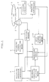
- Fig. 1 is a block diagram showing a system of the present invention;
- Fig. 2 is a schematic illustration showing a recorded CD-WO disk;
- Fig. 3 is a schematic illustration showing an unrecorded CD-WO disk; and
- Figs. 4 and 5 are flowcharts showing operations of the system.
- Referring to Fig. 1 showing the system of the present invention, a CD-
WO disk 1 is mounted on a turn table of a recording device (not shown). A pregroove 1a having a wobbled inside wall is spirally formed in the CD-WO disk along a track thereon. The CD-WO disk 1 is rotated by a spindle motor through the turn table. Anoptical pickup 2 is provided for recording probrams and data on the disk and for reading information written on the disk with laser beams radiated therefrom. Thepickup 2 is controlled in the vertical direction on the disk by a focusingcontroller 3 for focusing the laser beam on the surface of the disk, and controlled in the radial direction of the disk by atracking controller 4 so that the beam traces the track and the pregroove 1a on the disk. - The
pickup 2 reads information on thedisk 1 and produces a signal dependent on the read out data. The signal is applied to asub-code reader 9. If thedisk 1 is a recorded disk, the sub-code data written in the PMA of the recorded disk, which includes the end time of the recorded program as described above, are extracted by thesub-code reader 9. Thus, the end of the recorded program can be detected by thesub-code reader 9. - On the other hand, in order to detect the absolute time on the
disk 1, ATIP signal reading means 10 is provided for receiving a tracking error signal from thetracking controller 4. The tracking error includes the wobbling frequency dependent on the pregroove. Since the wobbling wave is frequency-modulated, the ATIP can be detected from the tracking error signal. - Recorded condition detector means 7 is supplied with output signals of the
sub-code reader 9 and the ATIP signal reading means 10 for detecting whether thedisk 1 is a recorded disk or an unrecorded disk, and the end of the recorded program when the disk is the recorded disk. - In order to control the operation of the whole of the system, a
recording operation controller 5 is provided. Recording signal generating means 6 is provided for performing the encoding of information, optical modulation and so forth to produce a recording signal which is applied to theoptical pickup 2. Searching means 8 is provided for moving thepickup 2 in the radial direction in accordance with output signals of thecontroller 5 and the recorded condition detector means 7 based on the sub-code data and the ATIP data. - In operation, when the CD-
WO disk 1 is mounted on the turn table, the searching means 8 operates to search the PMA on the disk in accordance with a search command signal from the recording condition detector means 7. If the CD-WO disk is the recorded disk, sub-code data are written in the PMA, which is detected by the detector means 7. - From the sub-code data, the position of the end of the recoded program is detected. The detector means 7 produces a search signal, so that the searching means 8 operates to locate the pickup at the end position of the recorded program with an actual pause.
- Fig. 2 shows the relative position between the recorded CD-WO disk and the
pickup 2. - On the other hand, when the CD-WO disk is an unrecorded one, the detector means 7 produces a search signal. In accordance with the search signal, the searching means operates to search a position after the lead-in area with an actual pause, for example with a pause of 2 seconds. The position is detected from the ATIP, while moving the
pickup 2 by thetracking controller 4. Thus, the pickup is located at the desired position. Thereafter, a program signal to be recorded is fed to thepickup 2 to record it on the CD-WO disk. - Fig. 3 shows the position of the
pickup 2 on the unrecorded disk. From the figure, it will be seen that the actual pause is provided at the beginning of the program area. - The operation of the system will be described hereinafter with reference to Fig. 4.
- When the mounting of the CD-WO disk is detected at a step S1, the recorded condition is detected at a step S2. When demanding the recording is detected at a step S3, it is determined at a step S4 whether the disk is unrecorded disk. When the disk is a recorded disk, the end position of the recorded area is searched from the sub-code data in the PMA at a step S5, and the pickup is located at a position with an actual pause after the searched position. When the disk is an unrecorded one, the pickup is located at a position with an actual pause of 2 seconds after the lead-in area at a step S6. Thereafter, recording operation is started at a step S7.
- Fig. 5 shows the detecting operation at the step S2 in detail.
- At a step S21, the PMA is searched, and it is determined whether data is written in the PMA at a step S22. If data is written in the PMA, the program proceeds to a step S23. The fact that the data is written in the PMA means that the disk is a recorded disk. Accordingly, data recorded in the PMA is read out, and an unrecorded disk flug is cleared at a step S24. When it is determined that the disk is an unrecorded disk at the step 22, an unrecorded disk flag is set at a step S25.
- Thus, it is easily determined whether the disk is recorded or not by determining whether the unrecorded disk flag is set or not at the step S4 of Fig. 4.
- When the program is thus recorded in the program area of the CD-WO disk, recorded data such as a start time and an end time of the recorded data are written in the PMA, and TOC are written in the lead-in area based on the data in the PMA. Thereafter, blank data are written in the actual pause area. Ater that the recording of data can be easily performed on the CD-WO disk in accordance with the recorded TOC as is performed in the ordinary CD.
- In accordance with the present invention, a program can be recorded on the CD-WO disk without cutting off a beginning portion of the program.
- While the presently preferred embodiment of the present invention has been shown and described, it is to be understood that this disclosure is for the purpose of illustration and that various changes and modifications may be made without departing from the scope of the invention as set forth in the appended claims.
Claims (5)
- A system for recording a program and data on an optical disk (1) with an optical pickup (2), the optical disk (1) having a first area in which programs are mainly written, and a second area located before the first area in which a table of contents of the programs written in the first area is written, the system comprising:
determining means (7) for determining whether a program is written in the first area and for producing an unrecorded disk signal when no program is written in the first area; recording control means (5) responsive to the unrecorded disk signal for moving the optical pickup (2) to a predetermined position in the first area. - A system according to claim 1,
characterized in that
the determining means (7) produces the unrecorded disk signal when a table of contents is not written in the second area. - A system according to claim 1 or 2,
characterized in that
the optical disk (1) is a CD-write-once disk. - A system according to one of claims 1 - 3,
characterized in that
the recording control means (5) operates to locate the optical pickup (2) at a position with an actual pause at a beginning of the first area. - A system according to one of claims 1 - 4,
characterized in that
the first area is a program area and the second area is a program memory area (PMA).
Applications Claiming Priority (2)
| Application Number | Priority Date | Filing Date | Title |
|---|---|---|---|
| JP287992/90 | 1990-10-25 | ||
| JP2287992A JP3015449B2 (en) | 1990-10-25 | 1990-10-25 | Optical information recording device |
Publications (3)
| Publication Number | Publication Date |
|---|---|
| EP0482645A2 true EP0482645A2 (en) | 1992-04-29 |
| EP0482645A3 EP0482645A3 (en) | 1993-04-21 |
| EP0482645B1 EP0482645B1 (en) | 1997-01-02 |
Family
ID=17724401
Family Applications (1)
| Application Number | Title | Priority Date | Filing Date |
|---|---|---|---|
| EP91118170A Expired - Lifetime EP0482645B1 (en) | 1990-10-25 | 1991-10-24 | Optical recording system |
Country Status (4)
| Country | Link |
|---|---|
| US (1) | US5499225A (en) |
| EP (1) | EP0482645B1 (en) |
| JP (1) | JP3015449B2 (en) |
| DE (1) | DE69123933T2 (en) |
Cited By (12)
| Publication number | Priority date | Publication date | Assignee | Title |
|---|---|---|---|---|
| WO1994014159A1 (en) * | 1992-12-17 | 1994-06-23 | Samsung Electronics Co., Ltd. | Disk recording medium and reproduction method and apparatus thereof |
| EP0552985A3 (en) * | 1992-01-24 | 1995-02-01 | Pioneer Electronic Corp | Method and apparatus for reproducing information |
| EP0552986A3 (en) * | 1992-01-24 | 1995-09-20 | Pioneer Electronic Corp | Cd player |
| EP0712130A1 (en) * | 1994-11-11 | 1996-05-15 | Mitsumi Electric Company Ltd. | Optical disk write method |
| US5734787A (en) * | 1994-03-19 | 1998-03-31 | Sony Corporation | Optical disk having a particular format to store user-selected data, such as compressed video data or computed files, including a dedicated TOC region and an application TOC to identify the video compression format |
| WO1999017280A1 (en) * | 1997-09-26 | 1999-04-08 | Daewoo Electronics Co., Ltd. | Optical disc reproducing apparatus and method for searching a track |
| EP1054399A1 (en) * | 1999-05-20 | 2000-11-22 | Pioneer Corporation | Apparatus for manufacturing information record medium, information record medium, information recording apparatus and method |
| WO2001016946A1 (en) * | 1999-08-31 | 2001-03-08 | Matsushita Electric Industrial Co., Ltd. | Optical disk device and method for controlling the same |
| USRE38502E1 (en) | 1994-03-19 | 2004-04-20 | Sony Corporation | Method and apparatus for recovering TOC and user information from an optical disk and using the TOC information to access user tracks |
| EP1168313A3 (en) * | 1994-07-26 | 2004-05-06 | Pioneer Electronic Corporation | Multi-layered recording disk |
| USRE38802E1 (en) | 1994-03-19 | 2005-09-27 | Sony Corporation | Method for reproducing compressed information data from a disk using a spatial frequency less than the track pitch |
| CN1317698C (en) * | 2004-02-02 | 2007-05-23 | 三星电子株式会社 | Apparatus and method of performing pause motion of optical pickup |
Families Citing this family (8)
| Publication number | Priority date | Publication date | Assignee | Title |
|---|---|---|---|---|
| JPH0916966A (en) * | 1995-06-26 | 1997-01-17 | Pioneer Electron Corp | Information recording method and recording / reproducing apparatus |
| DE19755741A1 (en) | 1997-12-16 | 1999-06-17 | Thomson Brandt Gmbh | CD player for CD-like recording formats |
| JPH11283328A (en) * | 1998-02-02 | 1999-10-15 | Ricoh Co Ltd | Optical recording medium, information erasing method and information recording / reproducing system for optical recording medium |
| FR2804397B1 (en) * | 2000-02-02 | 2002-05-03 | Bosch Gmbh Robert | METHOD FOR MANUFACTURING A MASTER CYLINDER COMPRISING AN ADJUSTMENT STEP AND MASTER CYLINDER OBTAINED BY SAID METHOD |
| JP4226204B2 (en) * | 2000-09-14 | 2009-02-18 | パイオニア株式会社 | Optical recording medium, manufacturing apparatus and manufacturing method thereof |
| US20030128646A1 (en) * | 2002-01-09 | 2003-07-10 | Peter Nangle | Asymmetrical programming mechanism for non-volatile memory |
| KR100475094B1 (en) | 2002-09-16 | 2005-03-10 | 삼성전자주식회사 | Apparatus and method for detecting position of pickup |
| JP4726115B2 (en) * | 2005-04-20 | 2011-07-20 | アルパイン株式会社 | Disc changer |
Family Cites Families (10)
| Publication number | Priority date | Publication date | Assignee | Title |
|---|---|---|---|---|
| JPS6267731A (en) * | 1985-09-20 | 1987-03-27 | Fujitsu Ltd | Method and device for optical recording and reproduction |
| US4791623A (en) * | 1986-04-03 | 1988-12-13 | Optotech, Inc. | File management system for use in an optical data storage system |
| JP2565196B2 (en) * | 1986-09-30 | 1996-12-18 | ソニー株式会社 | Recording device and recording method |
| JP2578780B2 (en) * | 1986-10-16 | 1997-02-05 | ソニー株式会社 | Optical disk recording device |
| JP2663436B2 (en) * | 1987-05-25 | 1997-10-15 | ソニー株式会社 | Optical disk recording device |
| US5197053A (en) * | 1987-06-09 | 1993-03-23 | Deutsche Thomson-Brandt Gmbh | Compact disk reader |
| JPH02187979A (en) * | 1989-01-13 | 1990-07-24 | Sharp Corp | Disk recording and reproducing device |
| JP2621459B2 (en) * | 1989-02-07 | 1997-06-18 | ヤマハ株式会社 | Optical disk recording system |
| US5065388A (en) * | 1989-03-29 | 1991-11-12 | U.S. Philips Corporation | Method and apparatus for recording on a record carrier a table of contents identifying all the recorded data signals |
| US5043967A (en) * | 1990-08-20 | 1991-08-27 | International Business Machines Corporation | Structured data storage method and medium |
-
1990
- 1990-10-25 JP JP2287992A patent/JP3015449B2/en not_active Expired - Fee Related
-
1991
- 1991-10-24 EP EP91118170A patent/EP0482645B1/en not_active Expired - Lifetime
- 1991-10-24 DE DE69123933T patent/DE69123933T2/en not_active Expired - Fee Related
-
1994
- 1994-07-28 US US08/281,536 patent/US5499225A/en not_active Expired - Fee Related
Cited By (25)
| Publication number | Priority date | Publication date | Assignee | Title |
|---|---|---|---|---|
| EP0837473A3 (en) * | 1992-01-24 | 2000-07-05 | Pioneer Electronic Corporation | CD player |
| EP0552985A3 (en) * | 1992-01-24 | 1995-02-01 | Pioneer Electronic Corp | Method and apparatus for reproducing information |
| EP0552986A3 (en) * | 1992-01-24 | 1995-09-20 | Pioneer Electronic Corp | Cd player |
| EP1103975A3 (en) * | 1992-01-24 | 2004-06-16 | Pioneer Electronic Corporation | CD player |
| CN1057629C (en) * | 1992-12-17 | 2000-10-18 | 三星电子株式会社 | disc recording media |
| US5546368A (en) * | 1992-12-17 | 1996-08-13 | Samsung Electronics Co. Ltd. | Disk recording medium and reproduction method and apparatus thereof |
| AU666570B2 (en) * | 1992-12-17 | 1996-02-15 | Samsung Electronics Co., Ltd. | Disk recording medium and reproduction method and apparatus thereof |
| WO1994014159A1 (en) * | 1992-12-17 | 1994-06-23 | Samsung Electronics Co., Ltd. | Disk recording medium and reproduction method and apparatus thereof |
| USRE38502E1 (en) | 1994-03-19 | 2004-04-20 | Sony Corporation | Method and apparatus for recovering TOC and user information from an optical disk and using the TOC information to access user tracks |
| USRE38802E1 (en) | 1994-03-19 | 2005-09-27 | Sony Corporation | Method for reproducing compressed information data from a disk using a spatial frequency less than the track pitch |
| US5734787A (en) * | 1994-03-19 | 1998-03-31 | Sony Corporation | Optical disk having a particular format to store user-selected data, such as compressed video data or computed files, including a dedicated TOC region and an application TOC to identify the video compression format |
| USRE38621E1 (en) * | 1994-03-19 | 2004-10-12 | Sony Corporation | Optical disk having a particular format to store user-selected data, such as compressed video data or computed files, including a dedicated toc region and an application toc to identify the video compression format |
| EP1168313A3 (en) * | 1994-07-26 | 2004-05-06 | Pioneer Electronic Corporation | Multi-layered recording disk |
| EP0712130A1 (en) * | 1994-11-11 | 1996-05-15 | Mitsumi Electric Company Ltd. | Optical disk write method |
| US5721856A (en) * | 1994-11-11 | 1998-02-24 | Mitsumi Electric Co., Ltd. | Optical disk write method |
| WO1999017280A1 (en) * | 1997-09-26 | 1999-04-08 | Daewoo Electronics Co., Ltd. | Optical disc reproducing apparatus and method for searching a track |
| US6700843B1 (en) | 1999-05-20 | 2004-03-02 | Pioneer Corporation | Apparatus for manufacturing information record medium, information record medium, information recording apparatus and information recording method |
| EP1054399A1 (en) * | 1999-05-20 | 2000-11-22 | Pioneer Corporation | Apparatus for manufacturing information record medium, information record medium, information recording apparatus and method |
| US7206270B2 (en) | 1999-05-20 | 2007-04-17 | Pioneer Corporation | Apparatus for manufacturing information record medium, information record medium, information recording apparatus and information recording method |
| US7848202B2 (en) | 1999-05-20 | 2010-12-07 | Pioneer Corporation | Apparatus for manufacturing information record medium, information record medium, information recording apparatus and information recording method |
| US7719933B2 (en) | 1999-05-20 | 2010-05-18 | Pioneer Corporation | Apparatus for manufacturing information record medium, information record medium, information recording apparatus and information recording method |
| WO2001016946A1 (en) * | 1999-08-31 | 2001-03-08 | Matsushita Electric Industrial Co., Ltd. | Optical disk device and method for controlling the same |
| US6850473B1 (en) | 1999-08-31 | 2005-02-01 | Matsushita Electric Industrial Co., Ltd. | Optical disc device and method for controlling the same |
| KR100459797B1 (en) * | 1999-08-31 | 2004-12-04 | 마츠시타 덴끼 산교 가부시키가이샤 | Optical disk device and method for controlling the same |
| CN1317698C (en) * | 2004-02-02 | 2007-05-23 | 三星电子株式会社 | Apparatus and method of performing pause motion of optical pickup |
Also Published As
| Publication number | Publication date |
|---|---|
| EP0482645B1 (en) | 1997-01-02 |
| DE69123933D1 (en) | 1997-02-13 |
| DE69123933T2 (en) | 1997-08-14 |
| US5499225A (en) | 1996-03-12 |
| JP3015449B2 (en) | 2000-03-06 |
| JPH04162250A (en) | 1992-06-05 |
| EP0482645A3 (en) | 1993-04-21 |
Similar Documents
| Publication | Publication Date | Title |
|---|---|---|
| EP0482645B1 (en) | Optical recording system | |
| US5592463A (en) | Apparatus for and method for determining optimum power for recording information on recordable optical disc | |
| US5920526A (en) | Method for detecting a boundary between recorded and unrecorded areas on an optical disc | |
| US4853915A (en) | Optical recording/reproducing method and apparatus for optical disk medium having unique control parameters | |
| EP0407573B1 (en) | Disc recording apparatus | |
| US5926453A (en) | Optical disk having first and second recording areas with wobble frequencies that do not interfere with EFM signal | |
| EP0215133B1 (en) | Method and apparatus of constructing and recording list of recorded data in postscript-type optical disk | |
| US5642342A (en) | Apparatus for controlling the rotational speed of an optical-disc | |
| EP0642122B1 (en) | Method and system for recording information on an optical disk | |
| US7362671B2 (en) | Optical disc recording and/or playing apparatus and method | |
| EP0775998B1 (en) | Optical pickup controlling system | |
| EP0114509B1 (en) | Record disc reproducing apparatus | |
| JP2951417B2 (en) | Optical information recording device | |
| JP3182520B2 (en) | Optical information recording device and information recording method | |
| JP2951416B2 (en) | Optical information recording device | |
| JP3181892B2 (en) | Optical information recording device and optical information recording method | |
| JPH1027346A (en) | Information recording / reproducing device | |
| JP2001101662A (en) | Optical type information recording device and information recording method | |
| JPH04247328A (en) | Optical information recorder | |
| JPH04247324A (en) | Optical information recorder | |
| JPH10208369A (en) | Disc reproducing apparatus and head position calculating method | |
| JPH04255915A (en) | Optical information recordor | |
| JP2004199866A (en) | Disc reproducing apparatus and method | |
| JPS62214566A (en) | Address searching method | |
| JPH06215535A (en) | Searching method for disk |
Legal Events
| Date | Code | Title | Description |
|---|---|---|---|
| PUAI | Public reference made under article 153(3) epc to a published international application that has entered the european phase |
Free format text: ORIGINAL CODE: 0009012 |
|
| AK | Designated contracting states |
Kind code of ref document: A2 Designated state(s): DE FR GB NL |
|
| 17P | Request for examination filed |
Effective date: 19921023 |
|
| PUAL | Search report despatched |
Free format text: ORIGINAL CODE: 0009013 |
|
| AK | Designated contracting states |
Kind code of ref document: A3 Designated state(s): DE FR GB NL |
|
| 17Q | First examination report despatched |
Effective date: 19941215 |
|
| GRAG | Despatch of communication of intention to grant |
Free format text: ORIGINAL CODE: EPIDOS AGRA |
|
| GRAH | Despatch of communication of intention to grant a patent |
Free format text: ORIGINAL CODE: EPIDOS IGRA |
|
| GRAH | Despatch of communication of intention to grant a patent |
Free format text: ORIGINAL CODE: EPIDOS IGRA |
|
| GRAA | (expected) grant |
Free format text: ORIGINAL CODE: 0009210 |
|
| AK | Designated contracting states |
Kind code of ref document: B1 Designated state(s): DE FR GB NL |
|
| ET | Fr: translation filed | ||
| REF | Corresponds to: |
Ref document number: 69123933 Country of ref document: DE Date of ref document: 19970213 |
|
| PLBE | No opposition filed within time limit |
Free format text: ORIGINAL CODE: 0009261 |
|
| STAA | Information on the status of an ep patent application or granted ep patent |
Free format text: STATUS: NO OPPOSITION FILED WITHIN TIME LIMIT |
|
| 26N | No opposition filed | ||
| REG | Reference to a national code |
Ref country code: GB Ref legal event code: 746 Effective date: 19980921 |
|
| REG | Reference to a national code |
Ref country code: FR Ref legal event code: D6 |
|
| REG | Reference to a national code |
Ref country code: GB Ref legal event code: IF02 |
|
| PGFP | Annual fee paid to national office [announced via postgrant information from national office to epo] |
Ref country code: NL Payment date: 20061015 Year of fee payment: 16 |
|
| PGFP | Annual fee paid to national office [announced via postgrant information from national office to epo] |
Ref country code: GB Payment date: 20061018 Year of fee payment: 16 |
|
| PGFP | Annual fee paid to national office [announced via postgrant information from national office to epo] |
Ref country code: DE Payment date: 20061019 Year of fee payment: 16 |
|
| GBPC | Gb: european patent ceased through non-payment of renewal fee |
Effective date: 20071024 |
|
| NLV4 | Nl: lapsed or anulled due to non-payment of the annual fee |
Effective date: 20080501 |
|
| PG25 | Lapsed in a contracting state [announced via postgrant information from national office to epo] |
Ref country code: DE Free format text: LAPSE BECAUSE OF NON-PAYMENT OF DUE FEES Effective date: 20080501 |
|
| REG | Reference to a national code |
Ref country code: FR Ref legal event code: ST Effective date: 20080630 |
|
| PG25 | Lapsed in a contracting state [announced via postgrant information from national office to epo] |
Ref country code: NL Free format text: LAPSE BECAUSE OF NON-PAYMENT OF DUE FEES Effective date: 20080501 |
|
| PGFP | Annual fee paid to national office [announced via postgrant information from national office to epo] |
Ref country code: FR Payment date: 20061010 Year of fee payment: 16 |
|
| PG25 | Lapsed in a contracting state [announced via postgrant information from national office to epo] |
Ref country code: GB Free format text: LAPSE BECAUSE OF NON-PAYMENT OF DUE FEES Effective date: 20071024 |
|
| PG25 | Lapsed in a contracting state [announced via postgrant information from national office to epo] |
Ref country code: FR Free format text: LAPSE BECAUSE OF NON-PAYMENT OF DUE FEES Effective date: 20071031 |