EP0482660A1 - Dispositif d'entraînement d'un mélangeur - Google Patents
Dispositif d'entraînement d'un mélangeur Download PDFInfo
- Publication number
- EP0482660A1 EP0482660A1 EP91118235A EP91118235A EP0482660A1 EP 0482660 A1 EP0482660 A1 EP 0482660A1 EP 91118235 A EP91118235 A EP 91118235A EP 91118235 A EP91118235 A EP 91118235A EP 0482660 A1 EP0482660 A1 EP 0482660A1
- Authority
- EP
- European Patent Office
- Prior art keywords
- gear
- mixer
- transmission
- shaft
- bearing
- Prior art date
- Legal status (The legal status is an assumption and is not a legal conclusion. Google has not performed a legal analysis and makes no representation as to the accuracy of the status listed.)
- Granted
Links
- 230000005540 biological transmission Effects 0.000 claims abstract description 14
- 230000008878 coupling Effects 0.000 claims abstract description 5
- 238000010168 coupling process Methods 0.000 claims abstract description 5
- 238000005859 coupling reaction Methods 0.000 claims abstract description 5
- 239000011395 ready-mix concrete Substances 0.000 abstract 1
- 230000009467 reduction Effects 0.000 description 2
- 230000002411 adverse Effects 0.000 description 1
- 230000007246 mechanism Effects 0.000 description 1
- 230000004048 modification Effects 0.000 description 1
- 238000012986 modification Methods 0.000 description 1
Images
Classifications
-
- B—PERFORMING OPERATIONS; TRANSPORTING
- B28—WORKING CEMENT, CLAY, OR STONE
- B28C—PREPARING CLAY; PRODUCING MIXTURES CONTAINING CLAY OR CEMENTITIOUS MATERIAL, e.g. PLASTER
- B28C5/00—Apparatus or methods for producing mixtures of cement with other substances, e.g. slurries, mortars, porous or fibrous compositions
- B28C5/42—Apparatus specially adapted for being mounted on vehicles with provision for mixing during transport
- B28C5/4203—Details; Accessories
- B28C5/4206—Control apparatus; Drive systems, e.g. coupled to the vehicle drive-system
- B28C5/421—Drives
- B28C5/4217—Drives in combination with drum mountings; Drives directly coupled to the axis of rotating drums
-
- F—MECHANICAL ENGINEERING; LIGHTING; HEATING; WEAPONS; BLASTING
- F16—ENGINEERING ELEMENTS AND UNITS; GENERAL MEASURES FOR PRODUCING AND MAINTAINING EFFECTIVE FUNCTIONING OF MACHINES OR INSTALLATIONS; THERMAL INSULATION IN GENERAL
- F16H—GEARING
- F16H57/00—General details of gearing
- F16H57/02—Gearboxes; Mounting gearing therein
- F16H2057/02039—Gearboxes for particular applications
- F16H2057/02043—Gearboxes for particular applications for vehicle transmissions
- F16H2057/02056—Gearboxes for particular applications for vehicle transmissions for utility vehicles, e.g. tractors or agricultural machines
-
- F—MECHANICAL ENGINEERING; LIGHTING; HEATING; WEAPONS; BLASTING
- F16—ENGINEERING ELEMENTS AND UNITS; GENERAL MEASURES FOR PRODUCING AND MAINTAINING EFFECTIVE FUNCTIONING OF MACHINES OR INSTALLATIONS; THERMAL INSULATION IN GENERAL
- F16H—GEARING
- F16H57/00—General details of gearing
- F16H57/02—Gearboxes; Mounting gearing therein
- F16H57/021—Shaft support structures, e.g. partition walls, bearing eyes, casing walls or covers with bearings
- F16H2057/0216—Intermediate shaft supports, e.g. by using a partition wall
Definitions
- the invention relates to a gear arrangement for a ready-mixed concrete mixer, with a drive shaft of the concrete mixing drum via a hydraulic motor driving a planetary gear.
- a mixer gear is known in which the drive side is driven into the second stage of the planetary gear via a high-speed hydraulic motor (approx. 70 ccm) via the first stage of a planetary gear.
- the ring gear of the second stage planetary gear and the mixer gear housing form one part.
- the second stage planet carrier also forms the connection to an output flange.
- this known arrangement is technically quite complex, there is a considerable disadvantage with regard to noise emissions during operation.
- the object of the invention is to replace this known drive of a ready-mixed concrete mixer, consisting of a hydraulic pump, a high-speed hydraulic motor and a two-stage planetary gear for the purpose of substantial noise reduction in the operation of the vehicle by an arrangement in which the noise emission is not in the frequency range from 500 Hz to 2kHz lies.
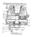
- the hydraulic motor is a radial piston motor, which is not mounted in the mixer gear housing on the output side, is slow-running and delivers high torque, the internal forces of which can be introduced via a bearing into an intermediate flange, so that the gear unit is a single-stage planetary gear unit and that Gear shaft is directly coupled to a sun gear, the output of which is carried out via a planet carrier on an arc tooth coupling, which transmits the torque to the drive shaft of the mixer drum.
- the mixer gear according to the invention consists of the single-stage planetary gear, which is driven by a sun gear.
- the drive takes place via the planet carrier and preferably a curved tooth coupling, which includes a flange and the bearing of the mixer drum.
- the gear shaft is directly coupled to the sun gear of the planetary gear, and the gear shaft can also be formed in one piece with the sun gear teeth.
- a radial piston motor 100 is connected to an intermediate flange by means of set screws.
- a sun gear shaft is rotatably mounted on the driven side of the radial piston motor by means of a centering bushing 24 and a bevel gear bearing 23.
- This intermediate flange 18 is in turn firmly connected to the mixer gear housing 1. Radial forces which could act on the shaft end located in the radial piston motor 100 do not occur in this embodiment.
- the sun gear shaft 2 has a sun gear formed in one piece with it, which meshes with planet gears 13, each planet gear 13 being non-positively connected to a planet carrier 12.
- the free end of this planet carrier is in engagement with an arc tooth coupling, which in the exemplary embodiment comprises a spherical spur gear 47.
- This spur gear 47 which is seated on a drive shaft 3, now transmits the torque to this shaft 3.
- the shaft 3 which merges into an output flange 40 is mounted in the mixer gear housing 1 by means of a spherical roller bearing. This is known as such and need not be explained in more detail.
- Essential to the invention is the combination of the radial piston motor described with the mixer gear part. For separate operation of one or both parts of this combination, additional essential components are required.
- a substantially reduced noise level can be achieved in the operation of the mixer vehicle in relation to the prior art, on the basis that a slow-speed device is provided and its connection to the transmission directly with the transmission shaft 2 follows via a spline.
- a compensating mechanism is produced on the one hand between the rotary cylinder to be guided very precisely and on the other hand the gear stage. Since these parts, in particular the rotary cylinder, require a very precise axial runout, there is relatively little play in the area of the planetary gear; due to the special mounting, however, no relative movements are applied to the sun gear shaft 2 from the gear unit, because the functional reliability of the "hydraulic motor" function groups is otherwise adversely affected.
- the internal forces of the hydraulic motor are absorbed by a separate bearing, the centering bushing 24 also serving as the transmitter for this function.
- the rotary cylinder is thus centered and the axial force system also takes place at this point.
- the bearing 23 produces the internal forces of the radial piston motor, that is the clearly identifiable internal forces acting to the right in the drawing and also the centering of the rotating group.
- the "hydraulic motor” group is sealed from the oil circuit in relation to the transmission (via the O-ring 60 and also via the shaft seal 5).
- the torque delivered by the slow-speed motor is transmitted in the ratio of the gear ratio to the output side of the transmission.
- the noise reduction in the operation of the concrete mixer results in principle from the special selection of the hydraulic motor as a slow-speed motor and from the fact that a relatively fast-running gear stage is eliminated, which contributes significantly to the noise emission due to the high meshing frequency.
- the proposed gear stage consequently runs considerably slower, so that the noise emission is practically eliminated.
- the components explained above also contribute to this, namely the intermediate flange 18, the centering bushing 24 and the shaft 2.
- a centering of the two housings takes place through the intermediate flange 18.
- an axial bearing 41 is provided, which also takes over the function of the bearing 23.
Landscapes
- Engineering & Computer Science (AREA)
- Mechanical Engineering (AREA)
- Structural Engineering (AREA)
- Retarders (AREA)
- Reciprocating Pumps (AREA)
- Preparation Of Clay, And Manufacture Of Mixtures Containing Clay Or Cement (AREA)
- Rotary Pumps (AREA)
Applications Claiming Priority (2)
| Application Number | Priority Date | Filing Date | Title |
|---|---|---|---|
| DE4034139 | 1990-10-26 | ||
| DE19904034139 DE4034139C3 (de) | 1990-10-26 | 1990-10-26 | Getriebeanordnung für einen Transportbetonmischer |
Publications (3)
| Publication Number | Publication Date |
|---|---|
| EP0482660A1 true EP0482660A1 (fr) | 1992-04-29 |
| EP0482660B1 EP0482660B1 (fr) | 1994-09-14 |
| EP0482660B2 EP0482660B2 (fr) | 2001-06-27 |
Family
ID=6417137
Family Applications (1)
| Application Number | Title | Priority Date | Filing Date |
|---|---|---|---|
| EP19910118235 Expired - Lifetime EP0482660B2 (fr) | 1990-10-26 | 1991-10-25 | Dispositif d'entraínement d'un mélangeur |
Country Status (3)
| Country | Link |
|---|---|
| EP (1) | EP0482660B2 (fr) |
| DE (1) | DE4034139C3 (fr) |
| ES (1) | ES2060271T5 (fr) |
Cited By (3)
| Publication number | Priority date | Publication date | Assignee | Title |
|---|---|---|---|---|
| EP0885702A1 (fr) * | 1997-06-10 | 1998-12-23 | Bonfiglioli Riduttori S.p.A. | Réducteur méchanique pour mélangeur à béton |
| DE10033661A1 (de) * | 2000-07-11 | 2002-01-24 | Zahnradfabrik Friedrichshafen | Hydrostatisch mechanisches Getriebe zum Antrieb einer Mischtrommel |
| CN103660031A (zh) * | 2013-12-27 | 2014-03-26 | 莱州亚通重型装备有限公司 | 矿用井下混凝土搅拌运输车 |
Families Citing this family (7)
| Publication number | Priority date | Publication date | Assignee | Title |
|---|---|---|---|---|
| DE4034139C3 (de) * | 1990-10-26 | 2003-10-30 | Sauer Danfoss Neumuenster Gmbh | Getriebeanordnung für einen Transportbetonmischer |
| DE19612309B4 (de) * | 1996-03-28 | 2005-11-17 | Zf Friedrichshafen Ag | Antriebsvorrichtung für eine Mischtrommel |
| DE19829411A1 (de) * | 1998-07-01 | 2000-01-05 | Zahnradfabrik Friedrichshafen | Hydrostatisch-mechanisches Getriebe zum Antrieb einer Mischtrommel |
| DE102004038503A1 (de) * | 2004-08-07 | 2006-02-23 | Zf Friedrichshafen Ag | Getriebe, insbesondere zum Antrieb einer Trommel eines Fahrmischers |
| DE102005012823A1 (de) * | 2005-03-17 | 2006-09-21 | Zf Friedrichshafen Ag | Antrieb für eine Mischtrommel |
| DE102012214432A1 (de) | 2012-08-14 | 2014-06-12 | Schaeffler Technologies Gmbh & Co. Kg | Fahrmischergetriebe |
| DE102014220408A1 (de) * | 2014-10-08 | 2016-04-14 | Zf Friedrichshafen Ag | Getriebe zum Antrieb einer Trommel eines Fahrmischers |
Citations (5)
| Publication number | Priority date | Publication date | Assignee | Title |
|---|---|---|---|---|
| DE1198266B (de) * | 1959-04-01 | 1965-08-05 | Rex Chainbelt Inc | Auf dem Rahmen eines Transportfahrzeugs angeordneter Betonmischer |
| FR2181171A5 (fr) * | 1972-04-19 | 1973-11-30 | Serieye Daniel | |
| FR2221029A5 (fr) * | 1973-03-05 | 1974-10-04 | Jaeger Machine Co | |
| GB1387151A (en) * | 1972-02-07 | 1975-03-12 | Challenge Cook Bros Inc | Drive coupling mechanism for mixer drum |
| DE2753246A1 (de) * | 1977-11-25 | 1979-05-31 | Prometheus Maschf Gmbh | Hochbelastbares umlaufgetriebe fuer rauhen betrieb |
Family Cites Families (7)
| Publication number | Priority date | Publication date | Assignee | Title |
|---|---|---|---|---|
| US3756095A (en) * | 1971-08-30 | 1973-09-04 | Envirotech Corp | Ring gear arrangement in a planetary drive |
| DE2341250A1 (de) * | 1973-08-16 | 1975-02-27 | Stetter Gmbh | Antriebsvorrichtung fuer die trommel von automischern |
| DE2904107C2 (de) * | 1979-02-03 | 1982-08-12 | Zahnradfabrik Friedrichshafen Ag, 7990 Friedrichshafen | Mischtrommelantrieb für einen Transportmischer |
| DE8326270U1 (de) * | 1983-09-09 | 1983-12-29 | Sauer Getriebe AG, 2350 Neumünster | Hochbelastbares Umlaufgetriebe für rauhen Betrieb |
| FR2576363B1 (fr) * | 1985-01-23 | 1989-04-21 | Poclain Hydraulics Sa | Mecanisme a fluide sous pression a rotor |
| DE4034139C3 (de) * | 1990-10-26 | 2003-10-30 | Sauer Danfoss Neumuenster Gmbh | Getriebeanordnung für einen Transportbetonmischer |
| DE4313025A1 (de) * | 1993-04-21 | 1994-10-27 | Zahnradfabrik Friedrichshafen | Hydrostatisch-mechanisches Getriebe zum Antrieb einer Mischtrommel |
-
1990
- 1990-10-26 DE DE19904034139 patent/DE4034139C3/de not_active Expired - Fee Related
-
1991
- 1991-10-25 EP EP19910118235 patent/EP0482660B2/fr not_active Expired - Lifetime
- 1991-10-25 ES ES91118235T patent/ES2060271T5/es not_active Expired - Lifetime
Patent Citations (5)
| Publication number | Priority date | Publication date | Assignee | Title |
|---|---|---|---|---|
| DE1198266B (de) * | 1959-04-01 | 1965-08-05 | Rex Chainbelt Inc | Auf dem Rahmen eines Transportfahrzeugs angeordneter Betonmischer |
| GB1387151A (en) * | 1972-02-07 | 1975-03-12 | Challenge Cook Bros Inc | Drive coupling mechanism for mixer drum |
| FR2181171A5 (fr) * | 1972-04-19 | 1973-11-30 | Serieye Daniel | |
| FR2221029A5 (fr) * | 1973-03-05 | 1974-10-04 | Jaeger Machine Co | |
| DE2753246A1 (de) * | 1977-11-25 | 1979-05-31 | Prometheus Maschf Gmbh | Hochbelastbares umlaufgetriebe fuer rauhen betrieb |
Cited By (5)
| Publication number | Priority date | Publication date | Assignee | Title |
|---|---|---|---|---|
| EP0885702A1 (fr) * | 1997-06-10 | 1998-12-23 | Bonfiglioli Riduttori S.p.A. | Réducteur méchanique pour mélangeur à béton |
| DE10033661A1 (de) * | 2000-07-11 | 2002-01-24 | Zahnradfabrik Friedrichshafen | Hydrostatisch mechanisches Getriebe zum Antrieb einer Mischtrommel |
| DE10033661B4 (de) * | 2000-07-11 | 2014-11-27 | Zf Friedrichshafen Ag | Hydrostatisch mechanisches Getriebe zum Antrieb einer Mischtrommel |
| CN103660031A (zh) * | 2013-12-27 | 2014-03-26 | 莱州亚通重型装备有限公司 | 矿用井下混凝土搅拌运输车 |
| CN103660031B (zh) * | 2013-12-27 | 2015-12-09 | 莱州亚通重型装备有限公司 | 矿用井下混凝土搅拌运输车 |
Also Published As
| Publication number | Publication date |
|---|---|
| DE4034139C3 (de) | 2003-10-30 |
| DE4034139A1 (de) | 1992-04-30 |
| EP0482660B2 (fr) | 2001-06-27 |
| ES2060271T5 (es) | 2001-10-01 |
| EP0482660B1 (fr) | 1994-09-14 |
| DE4034139C2 (de) | 1998-07-02 |
| ES2060271T3 (es) | 1994-11-16 |
Similar Documents
| Publication | Publication Date | Title |
|---|---|---|
| DE102017211881A1 (de) | Antriebseinrichtung zum Antreiben einer elektrischen Achse | |
| DE10040039A1 (de) | Wechselgetriebe-Anordnung | |
| DE3444562A1 (de) | Schaltgetriebe fuer motorfahrzeuge | |
| EP0482660B1 (fr) | Dispositif d'entraînement d'un mélangeur | |
| EP0248899A1 (fr) | Boite de changement a echelonnement multiple de vitesses. | |
| DE2610197A1 (de) | Drehmomentwandler | |
| DE19714528C2 (de) | Exzentergetriebe | |
| EP0962298B2 (fr) | Transmission pour extrudeuse à deux vis | |
| DE2937501A1 (de) | Gehaeuseanordnung fuer ein automatisches getriebe eines frontangetriebenen kraftfahrzeugs | |
| DE2734487A1 (de) | Konzentrisches untersetzungsgetriebe mit mehreren getriebezuegen | |
| EP1416190A2 (fr) | Engrenage angulaire à division de puissance | |
| DE10323705B4 (de) | Vorrichtung zum geregelten Verstellen der relativen Drehlage zwischen einer Kurbelwelle und einer Nockenwelle | |
| DE102020117269B3 (de) | Getriebeanordnung | |
| EP0676560B1 (fr) | Wolfrom-engrenage planétaire avec porte-satellites entraíné | |
| EP1915553B1 (fr) | Adaptateur, engrenage planetaire, entrainement, et procede | |
| DE3229951A1 (de) | Antriebsaggregat mit einer antriebsmaschine und einer hydrodynamischen bremse | |
| DE2647240B2 (de) | Stufenlos einstellbares hydraulischmechanisches Verbundgetriebe | |
| DE4306141A1 (de) | Verstelleinrichtung für Propellerpumpen | |
| WO2023169750A1 (fr) | Système d'engrenage d'essieu pour un essieu d'entraînement de véhicule motorisé | |
| DE102010062948A1 (de) | Getriebe einer Antriebsvorrichtung einer Mischtrommel | |
| DE3427817A1 (de) | Umlaufradreduziergetriebe | |
| DE4341728A1 (de) | Achsausgleichgetriebe für Kraftfahrzeuge | |
| DE4422444C2 (de) | Hydrodynamisch-mechanisches Verbundgetriebe zum Antrieb von drehzahlvariablen Arbeitsmaschinen und Verfahren zum Betreiben | |
| DE19963230B4 (de) | Umlaufgetriebe | |
| DE3231435C2 (fr) |
Legal Events
| Date | Code | Title | Description |
|---|---|---|---|
| PUAI | Public reference made under article 153(3) epc to a published international application that has entered the european phase |
Free format text: ORIGINAL CODE: 0009012 |
|
| AK | Designated contracting states |
Kind code of ref document: A1 Designated state(s): ES FR GB IT |
|
| 17P | Request for examination filed |
Effective date: 19921001 |
|
| 17Q | First examination report despatched |
Effective date: 19930628 |
|
| GRAA | (expected) grant |
Free format text: ORIGINAL CODE: 0009210 |
|
| AK | Designated contracting states |
Kind code of ref document: B1 Designated state(s): ES FR GB IT |
|
| ITF | It: translation for a ep patent filed | ||
| GBT | Gb: translation of ep patent filed (gb section 77(6)(a)/1977) |
Effective date: 19940921 |
|
| REG | Reference to a national code |
Ref country code: ES Ref legal event code: FG2A Ref document number: 2060271 Country of ref document: ES Kind code of ref document: T3 |
|
| ET | Fr: translation filed | ||
| PLBI | Opposition filed |
Free format text: ORIGINAL CODE: 0009260 |
|
| 26 | Opposition filed |
Opponent name: POCLAIN HYDRAULICS Effective date: 19950608 |
|
| PLBF | Reply of patent proprietor to notice(s) of opposition |
Free format text: ORIGINAL CODE: EPIDOS OBSO |
|
| PLBO | Opposition rejected |
Free format text: ORIGINAL CODE: EPIDOS REJO |
|
| APAC | Appeal dossier modified |
Free format text: ORIGINAL CODE: EPIDOS NOAPO |
|
| APAE | Appeal reference modified |
Free format text: ORIGINAL CODE: EPIDOS REFNO |
|
| APAE | Appeal reference modified |
Free format text: ORIGINAL CODE: EPIDOS REFNO |
|
| APAC | Appeal dossier modified |
Free format text: ORIGINAL CODE: EPIDOS NOAPO |
|
| PLAW | Interlocutory decision in opposition |
Free format text: ORIGINAL CODE: EPIDOS IDOP |
|
| RAP2 | Party data changed (patent owner data changed or rights of a patent transferred) |
Owner name: SAUER-DANFOSS (NEUMUENSTER) GMBH & CO OHG |
|
| PUAH | Patent maintained in amended form |
Free format text: ORIGINAL CODE: 0009272 |
|
| STAA | Information on the status of an ep patent application or granted ep patent |
Free format text: STATUS: PATENT MAINTAINED AS AMENDED |
|
| 27A | Patent maintained in amended form |
Effective date: 20010627 |
|
| AK | Designated contracting states |
Kind code of ref document: B2 Designated state(s): ES FR GB IT |
|
| GBTA | Gb: translation of amended ep patent filed (gb section 77(6)(b)/1977) |
Effective date: 20010808 |
|
| ITF | It: translation for a ep patent filed | ||
| REG | Reference to a national code |
Ref country code: ES Ref legal event code: DC2A Kind code of ref document: T5 Effective date: 20010705 |
|
| ET3 | Fr: translation filed ** decision concerning opposition | ||
| REG | Reference to a national code |
Ref country code: GB Ref legal event code: IF02 |
|
| PGFP | Annual fee paid to national office [announced via postgrant information from national office to epo] |
Ref country code: FR Payment date: 20021017 Year of fee payment: 12 |
|
| PGFP | Annual fee paid to national office [announced via postgrant information from national office to epo] |
Ref country code: GB Payment date: 20031006 Year of fee payment: 13 |
|
| PGFP | Annual fee paid to national office [announced via postgrant information from national office to epo] |
Ref country code: ES Payment date: 20031029 Year of fee payment: 13 |
|
| PG25 | Lapsed in a contracting state [announced via postgrant information from national office to epo] |
Ref country code: GB Free format text: LAPSE BECAUSE OF NON-PAYMENT OF DUE FEES Effective date: 20041025 |
|
| PG25 | Lapsed in a contracting state [announced via postgrant information from national office to epo] |
Ref country code: ES Free format text: LAPSE BECAUSE OF NON-PAYMENT OF DUE FEES Effective date: 20041026 |
|
| GBPC | Gb: european patent ceased through non-payment of renewal fee |
Effective date: 20041025 |
|
| PG25 | Lapsed in a contracting state [announced via postgrant information from national office to epo] |
Ref country code: FR Free format text: LAPSE BECAUSE OF NON-PAYMENT OF DUE FEES Effective date: 20050630 |
|
| REG | Reference to a national code |
Ref country code: FR Ref legal event code: ST |
|
| APAH | Appeal reference modified |
Free format text: ORIGINAL CODE: EPIDOSCREFNO |
|
| PG25 | Lapsed in a contracting state [announced via postgrant information from national office to epo] |
Ref country code: IT Free format text: LAPSE BECAUSE OF NON-PAYMENT OF DUE FEES;WARNING: LAPSES OF ITALIAN PATENTS WITH EFFECTIVE DATE BEFORE 2007 MAY HAVE OCCURRED AT ANY TIME BEFORE 2007. THE CORRECT EFFECTIVE DATE MAY BE DIFFERENT FROM THE ONE RECORDED. Effective date: 20051025 |
|
| REG | Reference to a national code |
Ref country code: ES Ref legal event code: FD2A Effective date: 20041026 |
|
| PG25 | Lapsed in a contracting state [announced via postgrant information from national office to epo] |
Ref country code: FR Free format text: LAPSE BECAUSE OF NON-PAYMENT OF DUE FEES Effective date: 20031031 |