EP0482723A2 - Dispositif pour le broyage du caoutchouc - Google Patents
Dispositif pour le broyage du caoutchouc Download PDFInfo
- Publication number
- EP0482723A2 EP0482723A2 EP91250195A EP91250195A EP0482723A2 EP 0482723 A2 EP0482723 A2 EP 0482723A2 EP 91250195 A EP91250195 A EP 91250195A EP 91250195 A EP91250195 A EP 91250195A EP 0482723 A2 EP0482723 A2 EP 0482723A2
- Authority
- EP
- European Patent Office
- Prior art keywords
- tunnel
- cooling tunnel
- main cooling
- refrigerant
- main
- Prior art date
- Legal status (The legal status is an assumption and is not a legal conclusion. Google has not performed a legal analysis and makes no representation as to the accuracy of the status listed.)
- Granted
Links
Images



Classifications
-
- B—PERFORMING OPERATIONS; TRANSPORTING
- B29—WORKING OF PLASTICS; WORKING OF SUBSTANCES IN A PLASTIC STATE IN GENERAL
- B29B—PREPARATION OR PRETREATMENT OF THE MATERIAL TO BE SHAPED; MAKING GRANULES OR PREFORMS; RECOVERY OF PLASTICS OR OTHER CONSTITUENTS OF WASTE MATERIAL CONTAINING PLASTICS
- B29B13/00—Conditioning or physical treatment of the material to be shaped
- B29B13/10—Conditioning or physical treatment of the material to be shaped by grinding, e.g. by triturating; by sieving; by filtering
-
- B—PERFORMING OPERATIONS; TRANSPORTING
- B29—WORKING OF PLASTICS; WORKING OF SUBSTANCES IN A PLASTIC STATE IN GENERAL
- B29B—PREPARATION OR PRETREATMENT OF THE MATERIAL TO BE SHAPED; MAKING GRANULES OR PREFORMS; RECOVERY OF PLASTICS OR OTHER CONSTITUENTS OF WASTE MATERIAL CONTAINING PLASTICS
- B29B17/00—Recovery of plastics or other constituents of waste material containing plastics
- B29B17/04—Disintegrating plastics, e.g. by milling
- B29B17/0404—Disintegrating plastics, e.g. by milling to powder
- B29B17/0408—Disintegrating plastics, e.g. by milling to powder using cryogenic systems
-
- B—PERFORMING OPERATIONS; TRANSPORTING
- B02—CRUSHING, PULVERISING, OR DISINTEGRATING; PREPARATORY TREATMENT OF GRAIN FOR MILLING
- B02C—CRUSHING, PULVERISING, OR DISINTEGRATING IN GENERAL; MILLING GRAIN
- B02C19/00—Other disintegrating devices or methods
- B02C19/18—Use of auxiliary physical effects, e.g. ultrasonic waves or irradiation, for disintegrating
- B02C19/186—Use of cold or heat for disintegrating
-
- B—PERFORMING OPERATIONS; TRANSPORTING
- B29—WORKING OF PLASTICS; WORKING OF SUBSTANCES IN A PLASTIC STATE IN GENERAL
- B29B—PREPARATION OR PRETREATMENT OF THE MATERIAL TO BE SHAPED; MAKING GRANULES OR PREFORMS; RECOVERY OF PLASTICS OR OTHER CONSTITUENTS OF WASTE MATERIAL CONTAINING PLASTICS
- B29B13/00—Conditioning or physical treatment of the material to be shaped
- B29B13/04—Conditioning or physical treatment of the material to be shaped by cooling
-
- F—MECHANICAL ENGINEERING; LIGHTING; HEATING; WEAPONS; BLASTING
- F25—REFRIGERATION OR COOLING; COMBINED HEATING AND REFRIGERATION SYSTEMS; HEAT PUMP SYSTEMS; MANUFACTURE OR STORAGE OF ICE; LIQUEFACTION SOLIDIFICATION OF GASES
- F25D—REFRIGERATORS; COLD ROOMS; ICE-BOXES; COOLING OR FREEZING APPARATUS NOT OTHERWISE PROVIDED FOR
- F25D3/00—Devices using other cold materials; Devices using cold-storage bodies
- F25D3/10—Devices using other cold materials; Devices using cold-storage bodies using liquefied gases, e.g. liquid air
- F25D3/11—Devices using other cold materials; Devices using cold-storage bodies using liquefied gases, e.g. liquid air with conveyors carrying articles to be cooled through the cooling space
-
- B—PERFORMING OPERATIONS; TRANSPORTING
- B29—WORKING OF PLASTICS; WORKING OF SUBSTANCES IN A PLASTIC STATE IN GENERAL
- B29B—PREPARATION OR PRETREATMENT OF THE MATERIAL TO BE SHAPED; MAKING GRANULES OR PREFORMS; RECOVERY OF PLASTICS OR OTHER CONSTITUENTS OF WASTE MATERIAL CONTAINING PLASTICS
- B29B17/00—Recovery of plastics or other constituents of waste material containing plastics
- B29B17/04—Disintegrating plastics, e.g. by milling
- B29B2017/0424—Specific disintegrating techniques; devices therefor
- B29B2017/0476—Cutting or tearing members, e.g. spiked or toothed cylinders or intermeshing rollers
-
- B—PERFORMING OPERATIONS; TRANSPORTING
- B29—WORKING OF PLASTICS; WORKING OF SUBSTANCES IN A PLASTIC STATE IN GENERAL
- B29C—SHAPING OR JOINING OF PLASTICS; SHAPING OF MATERIAL IN A PLASTIC STATE, NOT OTHERWISE PROVIDED FOR; AFTER-TREATMENT OF THE SHAPED PRODUCTS, e.g. REPAIRING
- B29C35/00—Heating, cooling or curing, e.g. crosslinking or vulcanising; Apparatus therefor
- B29C35/16—Cooling
- B29C2035/1616—Cooling using liquids
- B29C2035/1625—Cooling using liquids other than water
- B29C2035/165—Cooling using liquids other than water liquified gases
-
- B—PERFORMING OPERATIONS; TRANSPORTING
- B29—WORKING OF PLASTICS; WORKING OF SUBSTANCES IN A PLASTIC STATE IN GENERAL
- B29K—INDEXING SCHEME ASSOCIATED WITH SUBCLASSES B29B, B29C OR B29D, RELATING TO MOULDING MATERIALS OR TO MATERIALS FOR MOULDS, REINFORCEMENTS, FILLERS OR PREFORMED PARTS, e.g. INSERTS
- B29K2021/00—Use of unspecified rubbers as moulding material
-
- B—PERFORMING OPERATIONS; TRANSPORTING
- B29—WORKING OF PLASTICS; WORKING OF SUBSTANCES IN A PLASTIC STATE IN GENERAL
- B29K—INDEXING SCHEME ASSOCIATED WITH SUBCLASSES B29B, B29C OR B29D, RELATING TO MOULDING MATERIALS OR TO MATERIALS FOR MOULDS, REINFORCEMENTS, FILLERS OR PREFORMED PARTS, e.g. INSERTS
- B29K2105/00—Condition, form or state of moulded material or of the material to be shaped
- B29K2105/26—Scrap or recycled material
-
- B—PERFORMING OPERATIONS; TRANSPORTING
- B29—WORKING OF PLASTICS; WORKING OF SUBSTANCES IN A PLASTIC STATE IN GENERAL
- B29L—INDEXING SCHEME ASSOCIATED WITH SUBCLASS B29C, RELATING TO PARTICULAR ARTICLES
- B29L2030/00—Pneumatic or solid tyres or parts thereof
-
- Y—GENERAL TAGGING OF NEW TECHNOLOGICAL DEVELOPMENTS; GENERAL TAGGING OF CROSS-SECTIONAL TECHNOLOGIES SPANNING OVER SEVERAL SECTIONS OF THE IPC; TECHNICAL SUBJECTS COVERED BY FORMER USPC CROSS-REFERENCE ART COLLECTIONS [XRACs] AND DIGESTS
- Y02—TECHNOLOGIES OR APPLICATIONS FOR MITIGATION OR ADAPTATION AGAINST CLIMATE CHANGE
- Y02W—CLIMATE CHANGE MITIGATION TECHNOLOGIES RELATED TO WASTEWATER TREATMENT OR WASTE MANAGEMENT
- Y02W30/00—Technologies for solid waste management
- Y02W30/50—Reuse, recycling or recovery technologies
- Y02W30/52—Mechanical processing of waste for the recovery of materials, e.g. crushing, shredding, separation or disassembly
-
- Y—GENERAL TAGGING OF NEW TECHNOLOGICAL DEVELOPMENTS; GENERAL TAGGING OF CROSS-SECTIONAL TECHNOLOGIES SPANNING OVER SEVERAL SECTIONS OF THE IPC; TECHNICAL SUBJECTS COVERED BY FORMER USPC CROSS-REFERENCE ART COLLECTIONS [XRACs] AND DIGESTS
- Y02—TECHNOLOGIES OR APPLICATIONS FOR MITIGATION OR ADAPTATION AGAINST CLIMATE CHANGE
- Y02W—CLIMATE CHANGE MITIGATION TECHNOLOGIES RELATED TO WASTEWATER TREATMENT OR WASTE MANAGEMENT
- Y02W30/00—Technologies for solid waste management
- Y02W30/50—Reuse, recycling or recovery technologies
- Y02W30/62—Plastics recycling; Rubber recycling
-
- Y—GENERAL TAGGING OF NEW TECHNOLOGICAL DEVELOPMENTS; GENERAL TAGGING OF CROSS-SECTIONAL TECHNOLOGIES SPANNING OVER SEVERAL SECTIONS OF THE IPC; TECHNICAL SUBJECTS COVERED BY FORMER USPC CROSS-REFERENCE ART COLLECTIONS [XRACs] AND DIGESTS
- Y10—TECHNICAL SUBJECTS COVERED BY FORMER USPC
- Y10S—TECHNICAL SUBJECTS COVERED BY FORMER USPC CROSS-REFERENCE ART COLLECTIONS [XRACs] AND DIGESTS
- Y10S241/00—Solid material comminution or disintegration
- Y10S241/31—Rubber preparation
-
- Y—GENERAL TAGGING OF NEW TECHNOLOGICAL DEVELOPMENTS; GENERAL TAGGING OF CROSS-SECTIONAL TECHNOLOGIES SPANNING OVER SEVERAL SECTIONS OF THE IPC; TECHNICAL SUBJECTS COVERED BY FORMER USPC CROSS-REFERENCE ART COLLECTIONS [XRACs] AND DIGESTS
- Y10—TECHNICAL SUBJECTS COVERED BY FORMER USPC
- Y10S—TECHNICAL SUBJECTS COVERED BY FORMER USPC CROSS-REFERENCE ART COLLECTIONS [XRACs] AND DIGESTS
- Y10S241/00—Solid material comminution or disintegration
- Y10S241/37—Cryogenic cooling
-
- Y—GENERAL TAGGING OF NEW TECHNOLOGICAL DEVELOPMENTS; GENERAL TAGGING OF CROSS-SECTIONAL TECHNOLOGIES SPANNING OVER SEVERAL SECTIONS OF THE IPC; TECHNICAL SUBJECTS COVERED BY FORMER USPC CROSS-REFERENCE ART COLLECTIONS [XRACs] AND DIGESTS
- Y10—TECHNICAL SUBJECTS COVERED BY FORMER USPC
- Y10S—TECHNICAL SUBJECTS COVERED BY FORMER USPC CROSS-REFERENCE ART COLLECTIONS [XRACs] AND DIGESTS
- Y10S241/00—Solid material comminution or disintegration
- Y10S241/38—Solid waste disposal
Definitions
- the invention relates to a plant for crushing rubber, in particular used rubber, used tires, rubber parts and rubber waste, consisting of an inclined precooling tunnel containing a conveying device and which can be fed via an input shaft, and a refrigerant connected to the precooling tunnel by a connecting shaft and at least partially filled and provided with a conveyor main cooling tunnel and a crushing device downstream of the main cooling tunnel.
- Waste rubber also accumulates in large quantities in the form of car tire carcasses that can no longer be retreaded. Such old tires represent a significant disposal problem and generate a large amount of pollutant-containing exhaust gases in the usual disposal by burning, which in turn must be disposed of by suitable filter systems.
- Waste rubber is to be converted into a reusable material by granulation in accordance with the known method and thus processed again into a product.
- the elastic waste rubber is subcooled with the help of a refrigerant, namely liquid nitrogen to very low temperatures, approx. - 140 ° C, whereby it can become brittle and then ground.
- a refrigerant namely liquid nitrogen to very low temperatures, approx. - 140 ° C, whereby it can become brittle and then ground.
- the problem with the known method is to achieve cooling and embrittlement reaching into the core zone of the old tires to be shredded. This requires the refrigerant to be exposed to the tires for a sufficiently long time. At the same time, proper transport of the slowly cooling tires must be ensured in order to prevent heating due to friction.
- the object of the present invention is to provide a system of the type described in the introduction which ensures good cooling while continuously conveying the waste rubber to be shredded.
- This object is achieved in that the main cooling tunnel and the pre-cooling tunnel are connected to one another by means of a gasification pipe carrying at least one refrigerant.
- the loading shaft of the pre-cooling tunnel is covered with a sealing dome and a suction fan is assigned to the sealing dome, with which damp air penetrating with the rubber parts can be canceled, and that the loading shaft has a loading opening through which the pre-cooling tunnel can be opened by means of a Pendulum flap can be loaded and which can be at least partially closed by a closure means.
- the interior of the main cooling tunnel is limited by a lateral partition in the width and below the bend of the conveyor device by a free space limitation and the free space thus divided Space is filled with insulating backfills.
- the precooling tunnel and the main cooling tunnel have stable tunnel walls and the stable tunnel walls are slidingly supported on tunnel bearings. These measures prevent a direct connection between the inner tube of the main cooling tunnel or the pre-cooling tunnel that carries the refrigerant.
- the application of cold can lead to a volume contraction in the tubes of the cooling tunnels, which can be 20 to 30 mm over the entire length.
- the tunnel walls are mounted on lubricious plastic, and it is also provided that the main cooling tunnels are provided with a change in length compensation.
- the delivery device with an angle from the refrigerant charge and through a discharge opening, which is sealed off from outside air by a lock system, is led out of the interior of the main cooling tunnel in an end face. This prevents the ingress of humidity and prevents freezing.
- the precooling tunnels and the main cooling tunnels are provided with vacuum insulation.
- the recycling system 10 shown schematically in FIGS. 1 and 2 essentially consists of a tubular pre-cooling tunnel 11 and a main cooling tunnel 12 arranged downstream of the pre-cooling tunnel 11 , can be loaded.
- the cutting device 15 consists of a punching table 18, on which the recycled material 17 is deposited by the feed conveyor belt 16 and large pieces are roughly shredded with a retractable punching knife 19.
- the recycling material 17 comminuted in this way by the cutting device 15 is successively transferred from one below the punching table 18 arranged feed belt 20 in the conveying direction 70 (arrow) to a loading shaft 13, which is provided above a bottom region 65 of the pre-cooling tunnel 11.
- FIG. 2 shows, two recycling systems 10 running parallel to one another are provided for better utilization and can be operated alternately by the cutting device 15.
- a distributor for example in the form of a pendulum flap 23, is assigned to the feed belt 20 in the area of the feed chutes 13 provided next to one another and distributes the incoming recycling material 17 under computer control.
- the loading shafts 13 are provided with side loading openings 21 which are provided with a curtain 22, for example a chain curtain or a sluice flap, in order to avoid cold drains.
- Each loading chute 13 is closed at the top with a closing dome 14.
- a suction fan 24 is provided in the end dome 14, which sucks up any moisture-laden air that may have penetrated from the bottom region 65 of the precooling tunnel 11.
- the precooling tunnel 11 consists of a solid outer tunnel wall 25, for example a steel tube, which is mounted on a sliding bearing 26 to compensate for the cold-induced volume contraction in a sliding manner.
- a conveyor 27 is provided, for example a chain conveyor made of V2A steel or a wire mesh conveyor belt, which is provided with drivers 28.
- the precooling tunnel 11 is oriented starting from the bottom region 65 and extends obliquely upward to a connecting shaft 31 arranged above the main cooling tunnel 12.
- a plurality of fans 29 and 30 are arranged in the pre-cooling tunnel 11, which swirl the cold coming from the main cooling tunnel 12 through the gasification tubes 48 and convey it in the direction of the bottom region 65. Supported by the suction fans 24 in the end domes 14, a circulating refrigerant gas is thus created, which flows in countercurrent to the recycling material 17 conveyed upwards.
- the recycling material 17 falling into the floor area 65 of the pre-cooling tunnel 11 at room temperature is thus pre-cooled to approximately -80 ° C. to -140 ° C. on its way to the connecting shaft 31.
- the recycling material 17, which has been precooled in this way, is transferred in the connecting shaft 31 to the main cooling tunnel 12, where it falls into a refrigerant 38 via guide plates 34.
- the fill level of the refrigerant 38 is regulated with the aid of a fill level indicator 39.
- the refrigerant 38 for example liquid nitrogen, has a temperature of approximately -195 ° C.
- the recycling material 17 that falls in at -80 ° C. to -140 ° C. is relatively warm, as a result of which it is immersed when it is immersed in the much colder refrigerant 38 to a boil, ie. gasification of nitrogen occurs.
- the gaseous nitrogen is introduced via the gasification pipes 48 from the main cooling tunnel 12 approximately in the area of the connecting shaft 31 into the pre-cooling tunnel 11. This creates a refrigerant gas flow 71 which runs in the direction of the bottom region 65.
- This refrigerant gas flow 71 can be amplified by fans 69 arranged in the gasification tubes 48 and its direction can be stabilized.
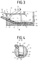
- the main cooling tunnel 12 also consists of a stable outer tunnel wall 35 and is arranged essentially horizontally. It is slidably supported on a tunnel bearing 37, which in turn stands on a cooling tunnel base 36. To compensate for the temperature-related length fluctuations, a length change compensation 77 is provided, in which the main cooling tunnel 12 can change its length.
- the connecting shaft 31 is provided with a tightly closable inspection opening 33 through which both the pre-cooling tunnel 11 and the main cooling tunnel 12 are accessible.
- a conveyor device 41 for example a chain conveyor belt made of V2A steel, which is provided with drivers 28, is arranged in the interior 40 of the main cooling tunnel 12.
- the recycled material 17 that is thrown in is completely immersed in the refrigerant 38 and is subcooled in the conveying direction 70 (arrow) down to its core to approx. -120 ° C to -190 ° C.
- the conveying device 41 runs essentially horizontally in the refrigerant 38. In the region of the end face 32 opposite the connecting shaft 31, the conveying device 41 is provided with an angled portion 64 and initially runs obliquely upwards out of the refrigerant 38 and then out through an outlet opening 43 out of the interior 40 of the main cooling tunnel 12. The now deep-frozen recycling material 17 is then transferred to a so-called trouser piece 44 for distribution to downstream, paired crushing devices 46.
- FIG. 4 shows, in the main cooling tunnel 12, essentially vertical side partition walls 52 are arranged on both sides of the conveying device 41.
- the interior 40 of the main cooling tunnel 12 is reduced by the dead space which is basically not required and which is caused by the tubular tunnel diameter.
- This dead space is backfilled with a backfill 53 made of an insulating material.
- the amount of refrigerant 38 required, which is a not inconsiderable cost factor, can thus be significantly reduced.
- the interior 40 of the main cooling tunnel 12 is insulated from the outer tunnel wall 35 by insulation 50, which is provided with vacuum insulation 49 on the outside.
- the inside of the insulation 50 has an inner coating 51 which is resistant to the refrigerant 38.
- a free space limitation 42 is provided below the bend 64 of the conveyor 41, which also reduces the amount of refrigerant 38 required to fill the main cooling tunnel 12.
- a cold-insulating cover 45 is provided above the trouser piece 44.
- FIG. 5 shows, two crushing devices 46 are assigned to each of the main cooling tunnels 12 arranged in pairs. These crushing devices 46 are each loaded with a trouser piece 44, as shown in detail in FIG. 6.
- a trouser piece 44 has a feed opening 54 through which the frozen recycled material 17 can fall into the breaking devices 46.
- a lock system 55 is provided in the area of the feed opening 54, which consists of an upper lock flap 56 and lower lock flaps 57.
- the lock flaps 57 are arranged in pairs and, under computer control, feed the crushing devices 46, which are also arranged in pairs.
- the lock system 55 also prevents the ingress of moisture-laden outside air. This prevents water from entering the cooling tunnels 11 and 12, because water can freeze the moving parts, for example the conveying devices 27 and 41, from freezing.
- partition walls 58 are provided in the lock system 55, which run essentially vertically.
- nose or roller crushers 66 can be arranged, with which the frozen recycling material 17 can be pre-shredded before it gets into the crushing devices 46 for crushing.
- the nose breakers 66 consist of breaker rollers 67 on which breaker lugs 68 are arranged.
- Rotatable blow bars 59 are provided in the breaking devices 46 and can be set in rotating motion by a blow bar drive 60.
- An electric motor is provided as the blow bar drive 60, for example.
- Fixed baffle bars 61 are arranged on the inner wall of a crusher 46 and, in cooperation with the blow bars 59, smash the recycled material 17 entered.
- the blow bars 59 are arranged vertically and offset by 90 ° on an axis of rotation 72.
- the crushers 46 have sieve trays 73 provided which have a plurality of bores 74. Beneath these sieve trays 73 there are provided fine impact bars 75 which rotate in fine grinding chambers 76 also provided below the sieve trays 73. In this way, the material to be recycled 17 which has passed through the bores 74 into the fine grinding chambers 76 located below the sieve trays 73 is ground even more intensively and thus more finely.
- the textile or metallic reinforcement inserts that are usually present in used tires are also exposed.
- the crushing devices 46 can be emptied through a discharge opening 62. From the discharge openings 62, the now recycled material 17, which has now been ground and granulated into a relatively broad grain fraction, falls onto a discharge conveyor belt 47, above which an overband magnet 63 is arranged.
- the metallic reinforcing inserts are first separated out.
- the thus pre-cleaned recycling material 17 is viewed and classified by a separation system, not shown in detail.
- the relatively finely comminuted textile reinforcement inserts are also separated and the ground recycled material 17 is divided into different sized grain fractions and then filled for further processing.
- the discharge conveyor belt 47 is provided with a conveyor belt cover 78.
- the conveyor belt cover 78 In order to gain access to the discharge openings 62 of the crushing devices 46, the conveyor belt cover 78 is provided with viewing flaps 79.
- the conveyor belt cover 78 consists of a rear wall 80 facing the trousers pieces 44, which is provided with a plurality of stiffeners 82. Slides 81 are provided between the discharge openings 62 of the crushing devices 46 and the conveyor belt cover 78.
- the conveyor belt overlap 78 is provided with front limits 83 with which they laterally limit the discharge conveyor belt 47.
- an overband magnet 63 is provided above the discharge conveyor belt 47, with which metallic components can be pulled out of the ground recycling material 17.
Landscapes
- Engineering & Computer Science (AREA)
- Mechanical Engineering (AREA)
- Physics & Mathematics (AREA)
- Thermal Sciences (AREA)
- Toxicology (AREA)
- Food Science & Technology (AREA)
- Chemical & Material Sciences (AREA)
- Combustion & Propulsion (AREA)
- Environmental & Geological Engineering (AREA)
- Health & Medical Sciences (AREA)
- General Engineering & Computer Science (AREA)
- Processing Of Solid Wastes (AREA)
- Disintegrating Or Milling (AREA)
- Processing And Handling Of Plastics And Other Materials For Molding In General (AREA)
- Separation, Recovery Or Treatment Of Waste Materials Containing Plastics (AREA)
- Addition Polymer Or Copolymer, Post-Treatments, Or Chemical Modifications (AREA)
- Crushing And Pulverization Processes (AREA)
- Compositions Of Macromolecular Compounds (AREA)
Applications Claiming Priority (2)
| Application Number | Priority Date | Filing Date | Title |
|---|---|---|---|
| DE19904033599 DE4033599C3 (de) | 1990-10-23 | 1990-10-23 | Anlage zum Zerkleinern von weichem Material, insbesondere Altgummi |
| DE4033599 | 1990-10-23 |
Publications (3)
| Publication Number | Publication Date |
|---|---|
| EP0482723A2 true EP0482723A2 (fr) | 1992-04-29 |
| EP0482723A3 EP0482723A3 (en) | 1992-06-10 |
| EP0482723B1 EP0482723B1 (fr) | 1995-09-27 |
Family
ID=6416831
Family Applications (1)
| Application Number | Title | Priority Date | Filing Date |
|---|---|---|---|
| EP19910250195 Expired - Lifetime EP0482723B1 (fr) | 1990-10-23 | 1991-07-18 | Dispositif pour le broyage du caoutchouc |
Country Status (10)
| Country | Link |
|---|---|
| US (1) | US5368240A (fr) |
| EP (1) | EP0482723B1 (fr) |
| JP (1) | JP3199787B2 (fr) |
| KR (1) | KR100211593B1 (fr) |
| AT (1) | ATE128401T1 (fr) |
| AU (1) | AU639370B2 (fr) |
| CA (1) | CA2053789C (fr) |
| DE (2) | DE4033599C3 (fr) |
| ES (1) | ES2082120T3 (fr) |
| ZA (1) | ZA918407B (fr) |
Cited By (6)
| Publication number | Priority date | Publication date | Assignee | Title |
|---|---|---|---|---|
| EP1088591A3 (fr) * | 1999-09-30 | 2001-12-12 | Mayekawa Mfg Co.Ltd. | Système de broyage de déchets à basse température |
| RU2283759C2 (ru) * | 2000-10-17 | 2006-09-20 | Реком Патент Энд Лицензе Гмбх | Линия для переработки утильрезины |
| WO2008078975A1 (fr) | 2006-12-27 | 2008-07-03 | Uab 'gumos Technologijos' | Appareil de destruction de l'enveloppe en caoutchouc de pneus et système de chargement et de déchargement de celui-ci |
| WO2008078974A1 (fr) | 2006-12-27 | 2008-07-03 | Uab 'gumos Technologijos' | Installation de retraitement des pneus usés et de modification de miettes de caoutchouc |
| WO2008098577A1 (fr) * | 2007-02-16 | 2008-08-21 | Arp Safe Aps | Procédé et installation pour le retrait de corps étrangers présents sur, dans et parmi des pneus mis au rebut |
| CN112027131A (zh) * | 2020-09-09 | 2020-12-04 | 杭州临安绿源助剂有限公司 | 一种流滴剂自动计量包装设备 |
Families Citing this family (28)
| Publication number | Priority date | Publication date | Assignee | Title |
|---|---|---|---|---|
| US5883140A (en) * | 1993-12-06 | 1999-03-16 | National Rubber L.L.C. | Process for regeneration of rubber |
| US5524838A (en) * | 1994-10-07 | 1996-06-11 | Ellers; H. John | Method and apparatus for processing tires to reclaim rubber, metal, and fabric |
| US5443567A (en) * | 1994-10-20 | 1995-08-22 | Pruett; Kearney L. | Tire carcass shredding method and apparatus |
| US5588600A (en) * | 1995-06-07 | 1996-12-31 | Perfido; Kenneth F. | Process and apparatus for making crumb rubber from vehicle tires |
| US6521706B1 (en) | 1998-01-12 | 2003-02-18 | Ppg Industries Ohio, Inc. | Composition of epoxy polymer, thermoplastic polymer, rubber particles and curing agent |
| GB2347365A (en) * | 1999-03-03 | 2000-09-06 | Thomas Hodgson | Vehicle tyre recycling process |
| US20030024369A1 (en) * | 1999-12-30 | 2003-02-06 | Dunn Brian Peter | Cutting apparatus for motor vehicle tyres |
| US6360547B1 (en) | 2000-01-07 | 2002-03-26 | Crumbrubber Technology Co., Inc. | Method and apparatus for cooling air to cryogenic temperatures for recycling processes |
| FR2804061A1 (fr) * | 2000-01-25 | 2001-07-27 | Dimitri Papachristou | Installation et procede pour reduire les pneumatiques usages en poudre ou granules |
| CA2345393A1 (fr) * | 2001-04-27 | 2002-10-27 | First American Scientific Corp. | Comminution cryogenique du caoutchouc |
| JP4658384B2 (ja) * | 2001-06-07 | 2011-03-23 | 三菱重工業株式会社 | 廃棄物の冷凍処理装置および冷凍処理方法 |
| US7445170B2 (en) | 2003-11-17 | 2008-11-04 | Lehigh Technologies Llc | Process and apparatus for manufacturing crumb and powder rubber |
| JP4902970B2 (ja) * | 2005-06-16 | 2012-03-21 | 株式会社ブリヂストン | ゴム組成物及びそれを用いた空気入りタイヤ |
| US7658967B2 (en) * | 2005-08-25 | 2010-02-09 | Pittsburgh Glass Works, Llc | Methods for applying sound dampening and/or aesthetic coatings and articles made thereby |
| US20070048504A1 (en) * | 2005-08-25 | 2007-03-01 | Dimario Joseph | Methods for applying sound dampening and/or aesthetic coatings and articles made thereby |
| JP4902987B2 (ja) * | 2005-12-05 | 2012-03-21 | 株式会社ブリヂストン | ゴム組成物及びそれを用いた空気入りタイヤ |
| US7886997B2 (en) * | 2008-01-10 | 2011-02-15 | Imperial Technologies, Inc. | Materials crusher and bottom dump feeder |
| FR2931089B1 (fr) * | 2008-05-19 | 2011-10-28 | Eric Gregoire | Procede de traitement des dechets organiques, notamment domestiques |
| CN103481401B (zh) * | 2012-12-28 | 2017-03-22 | 杭州东光科技有限公司 | 一种波纹管自动粉碎机 |
| CN106042210B (zh) * | 2016-06-02 | 2018-08-03 | 江苏华兴橡胶科技有限公司 | 一种再生胶用精炼配套设备 |
| CN106514901A (zh) * | 2016-11-08 | 2017-03-22 | 湛江市伟达机械实业有限公司 | 天然橡胶初加工工艺 |
| CN107756671B (zh) * | 2017-09-19 | 2019-07-09 | 卢寿同 | 一种高效节能环保全自动塑料热切粒机 |
| US11491493B2 (en) | 2018-05-30 | 2022-11-08 | Philip John Milanovich | Waste management system |
| US11325280B2 (en) | 2018-05-30 | 2022-05-10 | Philip John Milanovich | Waste management system |
| US11708135B2 (en) | 2018-05-30 | 2023-07-25 | Philip John Milanovich | Waste management system |
| US11273580B2 (en) | 2018-05-30 | 2022-03-15 | Philip John Milanovich | Waste management system |
| KR102827581B1 (ko) * | 2023-04-25 | 2025-07-01 | 김익경 | 폐타이어 재생 시스템 및 이를 이용한 재생 방법 |
| CN116474925B (zh) * | 2023-04-28 | 2023-10-13 | 扬州炳星机械有限公司 | 一种物料粉碎机水冷降温设备 |
Family Cites Families (32)
| Publication number | Priority date | Publication date | Assignee | Title |
|---|---|---|---|---|
| US1048869A (en) * | 1912-02-19 | 1912-12-31 | Stearns Roger Mfg Company | Apparatus for preparing and feeding fine fuel. |
| US2126776A (en) * | 1933-10-06 | 1938-08-16 | Standard Stoker Co Inc | Fuel pulverizer and feeder |
| US2447249A (en) * | 1944-10-13 | 1948-08-17 | Marison Company | Method of refrigerating an article by contact with a vaporizable refrigerant |
| FR972931A (fr) * | 1947-09-23 | 1951-02-05 | Dispositif de ventilation à direction rectiligne, applicable aux séchoirs pour pâtes alimentaires et autres produits | |
| DE1004460B (de) * | 1953-08-31 | 1957-03-14 | Knapsack Ag | Einrichtung zum Kaltmahlen von festen, zaehen Werkstoffen |
| US3101757A (en) * | 1961-04-24 | 1963-08-27 | Thomas P Hanson | Apparatus and method of debarking pulp wood utilizing liquified gasses |
| DE1604987C2 (de) * | 1963-08-09 | 1974-01-31 | Buettner-Schilde-Haas Ag, 4150 Krefeld | Bandtrockner für loses Gut |
| US3413818A (en) * | 1963-12-13 | 1968-12-03 | Fmc Corp | Immersion freezing |
| US3485055A (en) * | 1964-09-18 | 1969-12-23 | Air Reduction | Continuous freezer |
| US3345828A (en) * | 1965-06-11 | 1967-10-10 | Air Prod & Chem | Parallel flow cryogenic freezer |
| US3376710A (en) * | 1966-05-16 | 1968-04-09 | Hirtensteiner Walter Earl | Food freezing apparatus |
| US3527414A (en) * | 1967-11-14 | 1970-09-08 | Union Corp | Method and apparatus for stripping the insulation from metallic wire |
| US3618226A (en) * | 1969-10-24 | 1971-11-09 | Haas Friedrich Maschf | Apparatus for continuously drying web material especially textile material |
| US3718284A (en) * | 1971-04-26 | 1973-02-27 | V Richardson | Method of and apparatus for communiting rubber tires |
| US3771729A (en) * | 1971-06-17 | 1973-11-13 | Air Prod & Chem | Cryogenic comminution system |
| FR2180031A1 (en) * | 1972-04-13 | 1973-11-23 | Union Carbide Corp | Powdered plastic/elastomeric material prodn - by low temp grinding |
| JPS5229458B2 (fr) * | 1972-12-27 | 1977-08-02 | ||
| DE2337055C2 (de) * | 1973-07-20 | 1982-12-09 | Linde Ag, 6200 Wiesbaden | Verfahren und Vorrichtung zur Rückgewinnung der in einem Benzin-Luft-Gemisch enthaltenen Kohlenwasserstoffe |
| US3992899A (en) * | 1974-05-31 | 1976-11-23 | Messer Griesheim Gmbh | Device for cooling bulk material by low-boiling liquefied gas |
| US4020992A (en) * | 1975-11-20 | 1977-05-03 | Aluminum Company Of America | Separation of joined plastic and metal components |
| US4175396A (en) * | 1978-05-19 | 1979-11-27 | Air Products And Chemicals, Inc. | Cryogenic embrittlement freezer with gas lock |
| US4340076A (en) * | 1979-02-27 | 1982-07-20 | General Technology Applications, Inc. | Dissolving polymers in compatible liquids and uses thereof |
| US4229947A (en) * | 1979-08-06 | 1980-10-28 | Air Products And Chemicals, Inc. | Cryogenic freezer |
| GB2079917B (en) * | 1980-07-12 | 1984-03-14 | Air Prod & Chem | Tunnel freezers |
| US4403479A (en) * | 1981-09-02 | 1983-09-13 | Ivan Rasovich | Quick freezing system |
| DE3138839A1 (de) * | 1981-09-30 | 1983-04-14 | Deutsche Babcock Ag, 4200 Oberhausen | Abdichtung fuer eine rohrmuehle |
| DE3632987A1 (de) * | 1986-09-29 | 1988-03-31 | Wolfgang Decker | Anlage zum granulieren von feststoffkoerpern, insbesondere altreifen |
| US4813614A (en) * | 1987-08-10 | 1989-03-21 | Moore David R | Method and apparatus for treating waste products to recover the components thereof |
| US4783972A (en) * | 1987-10-29 | 1988-11-15 | Liquid Carbonic Corporation | N2 tunnel freezer |
| US4852358A (en) * | 1988-07-16 | 1989-08-01 | Union Carbide Corporation | Cryogenic combination tunnel freezer |
| DE8816558U1 (de) * | 1988-08-16 | 1989-11-23 | Westfalen AG, 4400 Münster | Vorrichtung zur Reinigung eines mit Dämpfen eines Fremdstoffs beladenen Abgases unter Rückgewinnung des Fremdstoffs |
| DE3915984C1 (fr) * | 1989-05-17 | 1990-09-06 | Wolfgang 6601 Kleinblittersdorf De Decker |
-
1990
- 1990-10-23 DE DE19904033599 patent/DE4033599C3/de not_active Expired - Fee Related
-
1991
- 1991-07-18 ES ES91250195T patent/ES2082120T3/es not_active Expired - Lifetime
- 1991-07-18 AT AT91250195T patent/ATE128401T1/de not_active IP Right Cessation
- 1991-07-18 EP EP19910250195 patent/EP0482723B1/fr not_active Expired - Lifetime
- 1991-07-18 DE DE59106587T patent/DE59106587D1/de not_active Expired - Fee Related
- 1991-09-20 AU AU84658/91A patent/AU639370B2/en not_active Ceased
- 1991-10-04 JP JP25809391A patent/JP3199787B2/ja not_active Expired - Fee Related
- 1991-10-11 KR KR1019910017864A patent/KR100211593B1/ko not_active Expired - Fee Related
- 1991-10-22 CA CA 2053789 patent/CA2053789C/fr not_active Expired - Fee Related
- 1991-10-22 ZA ZA918407A patent/ZA918407B/xx unknown
-
1993
- 1993-07-15 US US08/091,726 patent/US5368240A/en not_active Expired - Lifetime
Cited By (8)
| Publication number | Priority date | Publication date | Assignee | Title |
|---|---|---|---|---|
| EP1088591A3 (fr) * | 1999-09-30 | 2001-12-12 | Mayekawa Mfg Co.Ltd. | Système de broyage de déchets à basse température |
| RU2283759C2 (ru) * | 2000-10-17 | 2006-09-20 | Реком Патент Энд Лицензе Гмбх | Линия для переработки утильрезины |
| WO2008078975A1 (fr) | 2006-12-27 | 2008-07-03 | Uab 'gumos Technologijos' | Appareil de destruction de l'enveloppe en caoutchouc de pneus et système de chargement et de déchargement de celui-ci |
| WO2008078974A1 (fr) | 2006-12-27 | 2008-07-03 | Uab 'gumos Technologijos' | Installation de retraitement des pneus usés et de modification de miettes de caoutchouc |
| LT5522B (lt) | 2006-12-27 | 2008-10-27 | Uab "Gumos Technologijos" | Įrenginys padangų gumos apvalkalui suardyti, jo pakrovimo ir iškrovimo sistema |
| LT5521B (lt) | 2006-12-27 | 2008-10-27 | Uab "Gumos Technologijos" | Nusidėvėjusių padangų perdirbimo ir gumos trupinių modifikavimo įranga |
| WO2008098577A1 (fr) * | 2007-02-16 | 2008-08-21 | Arp Safe Aps | Procédé et installation pour le retrait de corps étrangers présents sur, dans et parmi des pneus mis au rebut |
| CN112027131A (zh) * | 2020-09-09 | 2020-12-04 | 杭州临安绿源助剂有限公司 | 一种流滴剂自动计量包装设备 |
Also Published As
| Publication number | Publication date |
|---|---|
| ES2082120T3 (es) | 1996-03-16 |
| KR920007768A (ko) | 1992-05-27 |
| CA2053789C (fr) | 2003-09-30 |
| DE59106587D1 (de) | 1995-11-02 |
| AU639370B2 (en) | 1993-07-22 |
| JPH05123600A (ja) | 1993-05-21 |
| EP0482723A3 (en) | 1992-06-10 |
| CA2053789A1 (fr) | 1992-04-24 |
| AU8465891A (en) | 1992-04-30 |
| ATE128401T1 (de) | 1995-10-15 |
| JP3199787B2 (ja) | 2001-08-20 |
| DE4033599A1 (de) | 1992-04-30 |
| KR100211593B1 (ko) | 1999-08-02 |
| DE4033599C2 (de) | 1994-04-14 |
| EP0482723B1 (fr) | 1995-09-27 |
| US5368240A (en) | 1994-11-29 |
| DE4033599C3 (de) | 1998-09-17 |
| ZA918407B (en) | 1992-07-29 |
Similar Documents
| Publication | Publication Date | Title |
|---|---|---|
| EP0482723B1 (fr) | Dispositif pour le broyage du caoutchouc | |
| WO2002032637A1 (fr) | Installation de traitement de caoutchouc usage | |
| DE9116445U1 (de) | Abfallaufbereitungsanlage | |
| EP0287935B2 (fr) | Dispositif de broyage pour récipients | |
| EP2585220B1 (fr) | Procédé et dispositif de broyage d'appareils réfrigérants | |
| EP0103240B1 (fr) | Broyeur à marteaux | |
| DE10357968B4 (de) | Recyclinganlage und Verfahren zur Kaltzerkleinerung von Gummi-Erzeugnissen, Stahl-Gummi-Verbunden und Stahlcord | |
| DE3037714C2 (de) | Anlage zur Aufbereitung von Haus- und Gewerbemüll | |
| DE4240389C2 (de) | Abfallentsorgungssystem | |
| DE2544964A1 (de) | Verfahren und vorrichtung zum abscheiden verschiedener fraktionen aus muell | |
| DE19533078A1 (de) | Verfahren und Vorrichtung zum Mahlen und Sichten von Mahlgut | |
| DE10062947A1 (de) | Aufbereitungseinrichtung für Gegenstände mit flüchtigen Inhaltsstoffen | |
| EP1372858B1 (fr) | Dispositif pour amener un materiau | |
| DE2333560C2 (de) | Sinteranlage zur Herstellung von Sinter aus Eisenerzen | |
| DE2448092A1 (de) | Zerkleinerer zum aufbereiten von duennwandigem schrott | |
| DE2844531A1 (de) | Verfahren zur aufarbeitung von abfall | |
| DE4133915C2 (de) | Verfahren zum Abtrennen von Treibgasen aus Schaumstoffen | |
| DE4005332A1 (de) | Abfallsortieranlage | |
| DE4244966B4 (de) | Verfahren und System zur Rückgewinnung eines Schäummittels in einem thermischen Isoliermaterial | |
| DD202225A5 (de) | Vorrichtung zum sammeln von gasen und teilchenmaterial in einem ofenbeschickungssystem | |
| EP2545141B1 (fr) | Dispositif de pyrolyse de substances organiques | |
| DE10336802B4 (de) | Verfahren und Anlage zum Trennen und Sortieren insbesondere von vorzerkleinerten Stoffen | |
| EP0501495B1 (fr) | Appareil de refroidissement de produits en morceaux ou granulaires | |
| DE2633873A1 (de) | Verfahren und vorrichtung zur gewinnung von eisenmetall aus schrottgegenstaenden | |
| EP0313034B1 (fr) | Véhicule pour le compostage de déchets ou ordures |
Legal Events
| Date | Code | Title | Description |
|---|---|---|---|
| PUAI | Public reference made under article 153(3) epc to a published international application that has entered the european phase |
Free format text: ORIGINAL CODE: 0009012 |
|
| PUAL | Search report despatched |
Free format text: ORIGINAL CODE: 0009013 |
|
| AK | Designated contracting states |
Kind code of ref document: A2 Designated state(s): AT BE CH DE DK ES FR GB GR IT LI LU NL SE |
|
| AK | Designated contracting states |
Kind code of ref document: A3 Designated state(s): AT BE CH DE DK ES FR GB GR IT LI LU NL SE |
|
| 17P | Request for examination filed |
Effective date: 19930318 |
|
| 17Q | First examination report despatched |
Effective date: 19950320 |
|
| GRAA | (expected) grant |
Free format text: ORIGINAL CODE: 0009210 |
|
| AK | Designated contracting states |
Kind code of ref document: B1 Designated state(s): AT BE CH DE DK ES FR GB GR IT LI LU NL SE |
|
| PG25 | Lapsed in a contracting state [announced via postgrant information from national office to epo] |
Ref country code: DK Effective date: 19950927 Ref country code: BE Effective date: 19950927 Ref country code: GR Free format text: LAPSE BECAUSE OF FAILURE TO SUBMIT A TRANSLATION OF THE DESCRIPTION OR TO PAY THE FEE WITHIN THE PRESCRIBED TIME-LIMIT Effective date: 19950927 |
|
| REF | Corresponds to: |
Ref document number: 128401 Country of ref document: AT Date of ref document: 19951015 Kind code of ref document: T |
|
| REF | Corresponds to: |
Ref document number: 59106587 Country of ref document: DE Date of ref document: 19951102 |
|
| ITF | It: translation for a ep patent filed | ||
| GBT | Gb: translation of ep patent filed (gb section 77(6)(a)/1977) |
Effective date: 19960106 |
|
| ET | Fr: translation filed | ||
| REG | Reference to a national code |
Ref country code: ES Ref legal event code: FG2A Ref document number: 2082120 Country of ref document: ES Kind code of ref document: T3 |
|
| PG25 | Lapsed in a contracting state [announced via postgrant information from national office to epo] |
Ref country code: AT Effective date: 19960718 |
|
| PG25 | Lapsed in a contracting state [announced via postgrant information from national office to epo] |
Ref country code: LI Effective date: 19960731 Ref country code: LU Free format text: LAPSE BECAUSE OF NON-PAYMENT OF DUE FEES Effective date: 19960731 Ref country code: CH Effective date: 19960731 |
|
| PLBE | No opposition filed within time limit |
Free format text: ORIGINAL CODE: 0009261 |
|
| STAA | Information on the status of an ep patent application or granted ep patent |
Free format text: STATUS: NO OPPOSITION FILED WITHIN TIME LIMIT |
|
| 26N | No opposition filed | ||
| REG | Reference to a national code |
Ref country code: CH Ref legal event code: PL |
|
| PGFP | Annual fee paid to national office [announced via postgrant information from national office to epo] |
Ref country code: SE Payment date: 19970710 Year of fee payment: 7 |
|
| PGFP | Annual fee paid to national office [announced via postgrant information from national office to epo] |
Ref country code: NL Payment date: 19970724 Year of fee payment: 7 |
|
| PG25 | Lapsed in a contracting state [announced via postgrant information from national office to epo] |
Ref country code: SE Free format text: LAPSE BECAUSE OF NON-PAYMENT OF DUE FEES Effective date: 19980719 |
|
| PG25 | Lapsed in a contracting state [announced via postgrant information from national office to epo] |
Ref country code: NL Free format text: LAPSE BECAUSE OF NON-PAYMENT OF DUE FEES Effective date: 19990201 |
|
| EUG | Se: european patent has lapsed |
Ref document number: 91250195.4 |
|
| NLV4 | Nl: lapsed or anulled due to non-payment of the annual fee |
Effective date: 19990201 |
|
| REG | Reference to a national code |
Ref country code: GB Ref legal event code: IF02 |
|
| REG | Reference to a national code |
Ref country code: GB Ref legal event code: 732E |
|
| REG | Reference to a national code |
Ref country code: FR Ref legal event code: TP |
|
| PGFP | Annual fee paid to national office [announced via postgrant information from national office to epo] |
Ref country code: ES Payment date: 20050728 Year of fee payment: 15 |
|
| PGFP | Annual fee paid to national office [announced via postgrant information from national office to epo] |
Ref country code: DE Payment date: 20051229 Year of fee payment: 15 |
|
| PGFP | Annual fee paid to national office [announced via postgrant information from national office to epo] |
Ref country code: IT Payment date: 20060731 Year of fee payment: 16 |
|
| PG25 | Lapsed in a contracting state [announced via postgrant information from national office to epo] |
Ref country code: DE Free format text: LAPSE BECAUSE OF NON-PAYMENT OF DUE FEES Effective date: 20070201 |
|
| REG | Reference to a national code |
Ref country code: ES Ref legal event code: FD2A Effective date: 20060719 |
|
| PGFP | Annual fee paid to national office [announced via postgrant information from national office to epo] |
Ref country code: GB Payment date: 20070802 Year of fee payment: 17 |
|
| PG25 | Lapsed in a contracting state [announced via postgrant information from national office to epo] |
Ref country code: ES Free format text: LAPSE BECAUSE OF NON-PAYMENT OF DUE FEES Effective date: 20060719 |
|
| PGFP | Annual fee paid to national office [announced via postgrant information from national office to epo] |
Ref country code: FR Payment date: 20070726 Year of fee payment: 17 |
|
| GBPC | Gb: european patent ceased through non-payment of renewal fee |
Effective date: 20080718 |
|
| REG | Reference to a national code |
Ref country code: FR Ref legal event code: ST Effective date: 20090331 |
|
| PG25 | Lapsed in a contracting state [announced via postgrant information from national office to epo] |
Ref country code: GB Free format text: LAPSE BECAUSE OF NON-PAYMENT OF DUE FEES Effective date: 20080718 |
|
| PG25 | Lapsed in a contracting state [announced via postgrant information from national office to epo] |
Ref country code: FR Free format text: LAPSE BECAUSE OF NON-PAYMENT OF DUE FEES Effective date: 20080731 |
|
| PG25 | Lapsed in a contracting state [announced via postgrant information from national office to epo] |
Ref country code: IT Free format text: LAPSE BECAUSE OF NON-PAYMENT OF DUE FEES Effective date: 20070718 |