EP0482773B1 - Kommunikationssteuerungssystem in einem asynchronen Zeitvielfachübermittlungsnetz (ATM) - Google Patents
Kommunikationssteuerungssystem in einem asynchronen Zeitvielfachübermittlungsnetz (ATM) Download PDFInfo
- Publication number
- EP0482773B1 EP0482773B1 EP91308883A EP91308883A EP0482773B1 EP 0482773 B1 EP0482773 B1 EP 0482773B1 EP 91308883 A EP91308883 A EP 91308883A EP 91308883 A EP91308883 A EP 91308883A EP 0482773 B1 EP0482773 B1 EP 0482773B1
- Authority
- EP
- European Patent Office
- Prior art keywords
- atm
- cell
- new
- identifier
- mid
- Prior art date
- Legal status (The legal status is an assumption and is not a legal conclusion. Google has not performed a legal analysis and makes no representation as to the accuracy of the status listed.)
- Expired - Lifetime
Links
- 238000004891 communication Methods 0.000 title claims description 21
- 230000006978 adaptation Effects 0.000 claims description 3
- 230000011218 segmentation Effects 0.000 claims 2
- 230000005540 biological transmission Effects 0.000 claims 1
- 208000037820 vascular cognitive impairment Diseases 0.000 description 97
- 230000015654 memory Effects 0.000 description 11
- 238000010586 diagram Methods 0.000 description 8
- 238000006243 chemical reaction Methods 0.000 description 7
- 238000000354 decomposition reaction Methods 0.000 description 3
- 238000000034 method Methods 0.000 description 3
- 239000000872 buffer Substances 0.000 description 2
- 230000006870 function Effects 0.000 description 2
- XUKUURHRXDUEBC-KAYWLYCHSA-N Atorvastatin Chemical compound C=1C=CC=CC=1C1=C(C=2C=CC(F)=CC=2)N(CC[C@@H](O)C[C@@H](O)CC(O)=O)C(C(C)C)=C1C(=O)NC1=CC=CC=C1 XUKUURHRXDUEBC-KAYWLYCHSA-N 0.000 description 1
- 108700026140 MAC combination Proteins 0.000 description 1
- 230000004308 accommodation Effects 0.000 description 1
- 238000010276 construction Methods 0.000 description 1
- 230000001419 dependent effect Effects 0.000 description 1
- 238000001914 filtration Methods 0.000 description 1
- 230000004044 response Effects 0.000 description 1
Images






Classifications
-
- H—ELECTRICITY
- H04—ELECTRIC COMMUNICATION TECHNIQUE
- H04L—TRANSMISSION OF DIGITAL INFORMATION, e.g. TELEGRAPHIC COMMUNICATION
- H04L49/00—Packet switching elements
- H04L49/30—Peripheral units, e.g. input or output ports
- H04L49/3009—Header conversion, routing tables or routing tags
-
- H—ELECTRICITY
- H04—ELECTRIC COMMUNICATION TECHNIQUE
- H04L—TRANSMISSION OF DIGITAL INFORMATION, e.g. TELEGRAPHIC COMMUNICATION
- H04L49/00—Packet switching elements
- H04L49/25—Routing or path finding in a switch fabric
- H04L49/253—Routing or path finding in a switch fabric using establishment or release of connections between ports
- H04L49/254—Centralised controller, i.e. arbitration or scheduling
-
- H—ELECTRICITY
- H04—ELECTRIC COMMUNICATION TECHNIQUE
- H04L—TRANSMISSION OF DIGITAL INFORMATION, e.g. TELEGRAPHIC COMMUNICATION
- H04L12/00—Data switching networks
- H04L12/54—Store-and-forward switching systems
- H04L12/56—Packet switching systems
- H04L12/5601—Transfer mode dependent, e.g. ATM
- H04L2012/5638—Services, e.g. multimedia, GOS, QOS
- H04L2012/5645—Connectionless
-
- H—ELECTRICITY
- H04—ELECTRIC COMMUNICATION TECHNIQUE
- H04L—TRANSMISSION OF DIGITAL INFORMATION, e.g. TELEGRAPHIC COMMUNICATION
- H04L49/00—Packet switching elements
- H04L49/55—Prevention, detection or correction of errors
Definitions
- the present invention relates to communication control systems using an Asynchronous Transfer Mode (ATM) Network and more particularly to a communication control system using an ATM network, which is constructed by a small number of virtual connections.
- ATM Asynchronous Transfer Mode
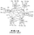
- FIG. 13 shows a conventional communication control system using an ATM network.
- the ATM network system of FIG. 13 includes six user interfaces IF1-IF6 which are connected to the corresponding groups of user units E11 - E1m, E21 - E2n, E31 - E3o, E41 - E4p, E51 - E5q, and E61 - E6r.
- the user interfaces IF1 - IF6 are connected to an ATM network 10, which have many fixed or semi-fixed virtual connections 11 which interconnect user interfaces IF1 - IF6 in a mesh-like manner.
- user interfaces IF1 - IF6 convert data packets outputted by user units E11 - E1m, E21 - E2n, E31 - E3o, E41 - E4p, E51 - E5q, and E61 - E6r to ATM cells and deliver the converted ATM cells to virtual connections 11 connected to a destination user interface.
- ATM network architecture for supporting the connectionless service discloses a protocol architecture for such a connectionless service, with a gateway architecture for supporting inter-LAN communication via the connectionless service function (CLSF).
- CLSF connectionless service function
- the present invention provides a communication control system as defined in Claim 1.
- a user interface and a connectionless service processor are connected by a fixed or semi-fixed virtual connection and connectionless service processors are interconnected by a virtual connection.
- a data packet outputted by a user terminal is converted by the corresponding user interface into an ATM cell, and then delivered by the virtual connection to the corresponding connectionless processor.
- the ATM cell is then transferred to a virtual connection for the destination user interface so as to carry out routing of the ATM cell.
- FIG. 1 illustrates a system structure of a communication control system using an ATM network according to one embodiment of the present invention.
- the communication control system comprises three distributed ATM exchanges 20, 30 and 40 and two centralized ATM exchanges 50 and 60.
- Distributed ATM exchange 20 is connected through user interface (LAN I/F) 21 and local area network (LAN) 22 to a plurality of user terminals 23.
- Distributed ATM exchange 30 is connected through user interface (LAN I/F) 31 and local area network (LAN) 32 to a plurality of user terminals 33.
- Distributed ATM exchange 40 is connected through user interface (LAN I/F) 41 and a local area network (LAN) 42 to a plurality of user terminals 43.
- LAN I/F local area network
- LANs 22, 32 and 42 are constructed by using 802 type LAN recommended by IEEE, 802. Although not shown in Fig. 1.
- distributed ATM exchanges 20, 30 and 40 are each connected through a plurality of user interfaces to the corresponding local area networks each of which accommodates a plurality of user terminals.
- user interfaces 21, 31 and 41 and local area network 22, 32 and 42 respectively show one of the plurality of user interfaces and local area networks.
- Centralized ATM exchanges 50 and 60 are connected to connectionless service (CLSF) processors 51 and 61, respectively.
- a semi-fixed virtual connection 71 is provided between user interface 21 and connectionless service processor 51 through distributed ATM exchange 20 and centralized ATM exchange 50.
- a semi-fixed virtual connection 72 is provided between connectionless service processors 51 and 61 through centralized ATM exchanges 50 and 60.
- a semi-fixed virtual connection 73 is provided between connectionless service processor 61 and user interface 31 through centralized ATM exchange 60 and distributed ATM exchange 30.
- a semi-fixed virtual connection 74 is provided between user interface 41 and connectionless service processor 51 through distributed ATM exchange 40 and centralized ATM exchange 50.
- communication is carried out among user terminals 23, 33 and 43 by using semi-fixed virtual connections 71, 72, 73 and 74 provided respectively between user interface 21 and connectionless service processor 51, between connectionless service processors 51 and 61, between connectionless service processor 61 and user interface 31, and between user interface 41 and connectionless service processor 51.
- User interfaces 21, 31 and 41 terminate protocols of local area networks 22, 32 and 42, add required headers to the data cells from the user terminals 23, 33 and 43, perform segmenting to the resulting data cells to form ATM cells and deliver the ATM cells into a wide band-ISDN network (ATM network) 100.
- ATM network wide band-ISDN network
- Connectionless service processors 51 and 61 carry out routing to the ATM cells delivered from user interfaces 21, 31 and 41 in a connectionless manner.
- E. 164 address stipulated by CCITT E. 164 is allocated to each of user interfaces 21, 31 and 41.
- FIG. 2 shows a protocol model for communication established between user terminals 23 and 33 accommodated in local area networks 22 and 32, respectively, in the FIG. 1 arrangement.
- FIG. 2(a) shows the connection between user terminals 23 and 33.
- FIG. 2(b) shows protocol models 23a, 21a, 100a, 31a and 33a of terminal 23, user interface 21, connectionless service processors 51 and 61, user interface 31 and terminal 33, respectively.
- Protocol model 23a of terminal 23 includes an upper layer, a network layer, a data link layer and a physical layer.
- the data link layer includes two sublayers; namely, a link layer control (LLC) layer and a media access control (MAC) layer.
- LLC link layer control
- MAC media access control
- Protocol model 21a of user interface 21 includes a network layer, a data link layer which includes a link layer control (LLC) layer and a media access control (MAC) layer, physical layer, an adaptation (AAL) layer which includes a convergence (CS) layer and a cell decomposition/assembly (SAR) layer, and an ATM layer and a Physical Medium Dependent (PDM) layer.
- LLC link layer control
- MAC media access control
- AAL adaptation
- CS convergence
- SAR cell decomposition/assembly
- PDM Physical Medium Dependent
- Protocol model 100a of each of connectionless service processors 51 and 61 includes a convergence (CS) layer, a cell decomposition/assembly (SAR) layer, an ATM layer and a PMD layer.
- CS convergence
- SAR cell decomposition/assembly
- Protocol model 31a of user interface 31 includes a network layer, an adaptation (AAL) layer which includes a convergence (CS) layer and a cell decomposition/assembly (SAR) layer, an ATM layer, a PMD layer, a data link layer which includes a link layer control (LLC) layer and a media access control (MAC) layer, and a physical layer.
- AAL adaptation
- CS convergence
- SAR cell decomposition/assembly
- ATM layer an ATM layer
- PMD layer a data link layer which includes a link layer control (LLC) layer and a media access control (MAC) layer
- MAC media access control
- Protocol model 33a of terminal 33 includes an upper layer, a network layer, a data link layer which includes a link layer control (LLC) layer and a media access control (MAC) layer, and a physical layer.
- LLC link layer control
- MAC media access control
- connectionless service processors 51, 61 each refer to an E. 164 address added to the header for routing purposes, so that protocol model 100a of each of connectionless service processors 51, 61 covers up to a CS layer.
- Connectionless service processors 51, 61 are connectionless, so that they do not provide error control and flow control.
- error control and flow control are performed by user terminals 23 and 33 on an end-to-end basis as in an ordinary local area network.
- FIG. 3 shows the structure of a protocol data unit (PDU) in each of the layers of user interfaces 21 and 31 of this embodiment.
- MAC protocol data unit (MAC-PDU) in the MAC layer includes a preamble field (PRE), a stop bit field (S), a MAC address field (AMC address), and a length field (LEN) in the header thereof, and a frame check sequence field (FCS) in the trailer thereof.
- LLC protocol data unit (LLC-PDU) in the LLC layer includes a service access point identifier field (SAPL) and a control field (CTRL) in the header thereof.
- SAPL service access point identifier
- CTRL control field
- Network protocol data unit (N-PDU) in the network layer includes a network address field in the header thereof.
- CS protocol data unit (CS-PDU) in the CS layer includes an E. 164 address field (E. 164), a length field (LEN), a sequence number field (SN), and a service access point identifier field (SAPL) in the header thereof.
- SAR protocol data unit (SAR-PDU) in the SAR layer includes a head field (SAR-H) and a trailer field (SAR-T).
- the header field (SAR-H) includes a segment type field (ST), a sequence number field (SN), and a multiplexing identifier field (MID).
- a trailer field (SAR-T) includes a length field (LEN) and a CRC check field (CRC).
- the ATM layer uses an ATM cell.
- CS-SDU CS service data units
- the CS layers each add a CS header including an E. 164 address and other data to the CS-SDU and transfers as a SAR service data unit (SAR-SDU) to the SAR layer.
- SAR-SDU is processed in the respective SAR and ATM layers to become an ATM cell, which is then sent out to a semi-fixed virtual connection for a nearby CLSF processor.
- the data link layer includes two sublayers MAC and LLC.
- the MAC layer performs filtering to the destination MAC address of an MAC-PDU received from local area networks 22, 32. If the address is directed to the MAC layer, MAC-SDU is delivered to the LLC layer.
- the MAC layer When the MAC layer receives MAC-SDU from the LLC layer, it adds a MAC header to MAC-SDU and delivers the resulting data as MAC-PDU to the local area network.
- the MAC address is determined as follows:
- the ARP is a process to check the MAC addressof a terminal or the like only the network address of which is known.
- the check end sends an ARP request packet in which the destination network address is the appropriate terminal and the destination MAC address is a broadcast.
- the terminal end checks the destination network address of the ARP request packet. If the address is of the terminal end, the terminal end transmits to the inquirer an ARP response packet in which the caller MAC address is of the terminal end.
- the LLC layer The LLC layer:
- the LLC layer transfers LLC-SDU from a service access point based on SAPI to the network layer.
- the AAL layer comprises two sublayers, namely, CS and SAR layers.
- the CS layer The CS layer:
- CS-SDU N-PDU
- E. 164 address checked in the network layer to the head of the CS header. This is because when CLSF processors 51, 61 transfer cells, the E. 164 address is required to be in a BOM cell (a cell having a head segment of CS-PDU) and a SSM cell (a cell in which CS-PDU is accommodated as a single segment).
- the SAR layer The SAR layer :
- SAR-SDU (CS-PDU) is divided into segments each having a size appropriate for accommodation in a SAR pay load, SAR-header SAR-H and SAR-trailer SAR-T are added to the respective segments and the resulting segments are delivered as SAR-PDU to the ATM layer.
- the format of SAR-PDU conforms to the format of AAL class 4 prescribed in I. 363.
- a cell header is added to ATM-SDU (SAR-PDU) and the resulting cell is sent as an ATM cell onto a virtual connection set beforehand between LAN I/F and a nearby CLSF processor.
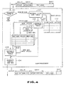
- FIG. 4 shows a routing algorithm of a cell in connectionless service processors (CLSF processors) 51, 61 in in the embodiment.
- Processors 51, 61 each receive an ATM cell, which includes a cell header Cell-H and a SAR header SAR-H, as will be seen from the structure of the ATM layer of FIG. 3.
- the cell header Cell-H includes a virtual identifier VPI and a virtual connection identifier VCI.
- SAR header SAR-H includes a segment type ST, a sequence number SN and a multiplexing identifier MID.
- connectionless service processor sets a transfer route on the basis of the E. 164 address added to the head of CS-PDU in the FIG. 3 CS layer.
- the route is set on the basis of the E. 164 address included in the head one of a plurality of ATM cells into which CS-PDU is segmented.
- This transfer route is constant during transfer of any one CS-PDU.
- the transfer route is determined by selecting a usable one of the virtual connections provided beforehand for service in the connectionless service processor.
- Each of the second and subsequent ones of the ATM cells into which CS-PDU is segmented is transferred while the output side virtual connection identifier VCI is being retrieved on the basis of the virtual connection identifier VCI and multiplexing identifier MID of the ATM cell input to the connectionless service processor (CLSF processor), and the header of the ATM cell is being converted.
- a table for the header conversion is set on the basis of the head cell.
- the segment type of the ATM cell inputted into the connectionless service processor is determined on the basis of the segment type ST of the SAR header SAR-H (step 101).
- the cell is classified into a BOM cell or a SSM cell and a COM cell or an EOM cell.
- E. 164 address table 110 is retrieved (step 102).
- E. 164 address table 110 is a new virtual path identifier VPI and a new virtual connection identifier VCI of a semi-fixed vertical connection in the direction in which a destination user interface (LAN I/F) is provided at each E. 164 address.
- E. 164 address table 110 is written on the basis of M-plane component data.
- E. 164 address table 110 is retrieved with the E. 164 address as a key to search a new virtual path identifier VPI and a new virtual connection identifier VCI of a semi-fixed virtual connection in the direction in which the destination user interface is provided.
- routing table 111 is rewritten on the basis of the new virtual identifier VPI and the new virtual connection identifier VCI obtained from E. 164 address table 110 (step 103).
- Routing table 111 is provided for each virtual connection identifier VCI. Routing table 111 is adapted to be written with new virtual path identifier VPI/new virtual connection identifier VCI and new multiplexing identifier MID for each multiplexing identifier MID.
- MID counter 112 includes a 10-bit binary counter provided for each new VCI.
- MID counter 112 is selected with a new virtual connection identifier VCI and is incremented to provide a new multiplexing identifier MID.
- Routing table 111 is selected with the virtual path identifier VPI/virtual connection identifier VCI and multiplexing identifier MID of the received ATM cell as keys, and new virtual path identifier VPI/new virtual connection identifier VCI and new multiplexing identifier MID obtained from MID counter 112 are written at the corresponding location of routing table 111.
- the MID counter is incremented when the BOM cell or SSM cell obtains new virtual connection identifier VCI. The count of this counter becomes a multiplexing identifier MID in new virtual connection identifiers VCI of the BOM cell or SSM cell and the train of subsequent cells (cells of the same CS-PDU).
- routine table 111 The data written once into routine table 111 in this way is maintained until a BOM or SSM cell having the same virtual connection identifier VCI and multiplexing identifier MID is received.
- Virtual path identifier VPI and virtual connection identifier VCI of the cell header Cell-H are rewritten as new virtual identifier VPI and new virtual connection identifier VCI, respectively, and the multiplexing identifier MID of SAR header SAR-H is rewritten as a new multiplexing identifier MID (step 104) and the written cell is provided as an output ATM cell.
- routing table 111 is retrieved with virtual path identifier VPI/virtual connection identifier VCI and multiplexing identifier MID of the input ATM cell as keys (step 105), and new virtual path identifier VPI/new virtual connection identifier VCI and new MID are read from routing table 111.
- Virtual path identifier VPI and virtual connection identifier VCI of cell header Cell-H are rewritten as new virtual path identifier VPI and new virtual connection identifier VCI, and SAR header SAR-H multiplexing identifier MID is rewritten as new multiplexing identifier MID (step 104), and the rewritten cell is provided as an output ATM cell.
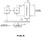
- FIG. 5 is a block diagram of the overall structure of the connectionless service processor (CLSI processor).
- CLSF processor includes header generator (HGN) 200, header exchanger (HEX) 300, ATM exchange interface 121, internal system bus 122 and local processor 123.
- HGN header generator
- HEX header exchanger
- ATM exchange interface 121 internal system bus 122
- local processor 123 local processor 123.
- Header exchanger 300 buffers a received ATM cell and delivers the virtual-path identifier VPI, virtual connection identifier VCI, multiplexing identifier MID, segment type ST, destination E. 164 address of the cell to header generator 200 and requests search for a new header to be used.
- header generator 200 receives this request, it determines new virtual path identifier VPI, virtual connection identifier VCI, and multiplexing identifier MID from the given data and returns it to header exchanger 300.
- Header exchanger 300 replaces new virtual path identifier VPI/new virtual connection identifier VCI, new multiplexina identifier MID in cell header Cell-H, SAR header SAR-H regions, respectively.
- FIG. 6 shows the detailed structure of header exchanaer 300 of FIG. 5. It includes serial/parallel converter (SP) 301, idle cell detectors 302, 3-port random access memory (3P-RAM) 303. 32-bit register 304 selector 305, parallel/serial converter (PS) 306, CRC computing unit 307, write address generator 308, read address generator 309, idle cell generator 310, data output register 311, data input register 312, and timing generator 313.
- SP serial/parallel converter
- P-RAM 3-port random access memory
- PS parallel/serial converter
- CRC computing unit 307 CRC computing unit
- write address generator 308 read address generator 309
- idle cell generator 310 data output register 311, data input register 312, and timing generator 313.
- 3-port random access memory 303 is used as a buffer storage region required for the conversion of the ATM cell header. It includes a 3-port RAM having a single write port and two read ports and has a storage capacity for 64 words of 32 bits. These read/write ports are each operable in an asynchronous manner.
- the storage region of memory 303 is divided into 4 blocks each having a length of one cell and a different block number.
- An ATM cell received synchronously with data CK externally is converted by SP301 to a 32-bit width data. Thereafter the data passes twice through a 32-bit width register of idle cell detector 302 to detect an idle cell and is then written through write port (WP) of 3-port random access memory 303.
- WP write port
- a block into which the data is written is selected from an idle block ist which write address generator 308 has. At this time, if the received ATM cell is an idle one, writing a cell into memory 303 is inhibited. After one ATM cell is written, the number of the block into which the ATM cell is written is transferred by handshaking to read address generator 309.
- Read address generator 309 which has received the number of the block into which the cell has been written first uses read port (RP) 1 of 3-port random access memory 303 to read the head 4 words of the ATM cell stored in the block having that number, and transfers them through data output register 311 to header generator 200.
- RP read port 1 of 3-port random access memory 303
- FIG. 7 shows the format of a cell-in memory 303 of this embodiment.
- the head 4 words include virtual path identifier VPI, virtual connection identifier VCI. multiplexing identifier MID, and segment type ST.
- the destination E. 164 address is stored in the head 60 bits (15 figures) of the SAR pay load in user interface (LAN I/F), so that the received cell is also contained in the head 4 words.
- Header generator 200 determines new virtual path identifier VPI, new virtual connection identifier VCI, and new multiplexing identifier MID on the basis of the received data and reports those data items to header exchanger 300 at predetermined timings.
- Read address generator 309 of header exchanger 300 starts to read from real port 2 (RP2) the ATM cell stored in the block having the above-mentioned block number, and merges new virtual path identifier VPI, new virtual connection identifier VCI, and multiplexing identifier MID reported by header generator ator 200 with data read from RP2 using a selector to thereby replace the header.
- RP2 real port 2
- header generator 200 fails in the determination of new virtual path identifier VPI, new virtual connection identifier VCI, and new multiplexing identifier MID (for example, if it uses the E. 164 address not registered in header generator 200 of the CLSF processor), it reports an error.
- an idle cell is outputted from idle cell generator 310 in place of the cell the header of which is to be converted and the idle cell is erased.
- the number of the block in which the idle cell is stored is delivered as the number of the block from which the cell has been read to write address generator 308.
- Read address generator 309 delivers to write address generator 309 in a handshaking manner the number of the block which has become idle after the cell is outputted.
- Reading data from port RP1 of memory 303 and reading a cell from port RP2 are performed in a pipelined manner.
- FIG. 8 shows the detailed structure of header generator 200, which includes a logical OR gate 201, data input register 202, data output register 203, VCI compressor 204, segment type determiner 205, E. 164 address table 206, 18-bit register 207, 3-state gate 208, routing table 209, MID counter 210, selector 211, VCI code/logical VCI conversion table 212, selector 213, MID table 214, 3-state gate 215, and local processor interface 216.
- a logical OR gate 201 data input register 202, data output register 203, VCI compressor 204, segment type determiner 205, E. 164 address table 206, 18-bit register 207, 3-state gate 208, routing table 209, MID counter 210, selector 211, VCI code/logical VCI conversion table 212, selector 213, MID table 214, 3-state gate 215, and local processor interface 216.
- SAR pay load has the head segment of CS-PDU. Since user interface (LAN I/F) adds an E. 164 address to the head of the CS header, these cells have the E. 164 address in the head of SAR pay load.
- LAN I/F user interface
- virtual path identifier VPI virtual path identifier VCI
- virtual connection identifier VCI multiplexing identifier MID, segment type ST
- destination E. 164 address from data output register 311 of header exchanger 300 are input to data input register 202.
- the destination E. 164 input to data input register 202 is used as a key to retrieve E. 164 table 206 to obtain new virtual path identifier VPI and new virtual connection identifier VCI. Since E. 164 table 206 compresses VPI and VCI to 8-bit data items and stores them as VCI codes, the VPI and VCI read from E. 164 table 206 are a new 8-bit VCI code, which will be described in more detail later.
- Segment type ST input to data input register 202 at this time is either BOM or SSM, so that the output of E. 164 table 206 and MID counter 210 including a 10-bit binary counter are enabled and routing table 209 and MID table 214 are enabled is be written.
- MID in new virtual path identifier VPI is then determined and new virtual connection identifier VCI by incriminating MID counter 210 including a 10-bit binary counter provided for each new virtual connection identifier VCI code.
- New VCI codes representing VPI and VCI are written into routing table 209 and MID is written into MID table 214 with the VCI code and MID as keys for the subsequent COM and EOM cells.
- New multiplexing identifier MID is intactly reported through data output register 206 to header exchanger 300.
- the new VCI code is expanded to a 28-bit new virtual path identiiier VPI and a new virtual connection identifier VCI by VCI code/logical VCI conversion table 212, and the results are reported through data output register 203 to header exchanger 300.
- segment type ST of data input register 202 indicates COM or EOM.
- the output of E. 164 table 206 and MID counter 210 are disabled and routing table 209 and MID table 214 are enabled to be read by the output of segment type determiner 205.
- Virtual path identifier VPI and virtual connection identifier VCI of data input register 202 are compressed to a 8-bit VCI code by VCI compressor 204 and applied to 18-bit register 207 to form the address of routing table 209 and MID table 214 together with multiplexing identifier MID of data input register 202.
- New VCI code and new multiplexing identifier MID representing new virtual path identifier VPI and new virtual connection identifier VCI are read from routing table 209 and MID table 214 with the VCI code and multiplexing identifier MID outputted from 18-bit resister 207 as keys.
- New multiplexing identifier MID is intactly reported through data output register 203 to header exchanger 300 while the new VCI code is expanded by VCI code/logical VCI conversion table 212 to new virtual path identifier VPI and new virtual connection identifier VCI each of 28 bits, which are then reported through data output register 203 to header exchanger 300.
- Virtual identifier VPI and virtual connection identifier VCI (logical VCI) each of 28 bits and of data input register 202 are input to VCI compressor 204 to be compressed into a 8-bit VCI, which is then outputted.
- New virtual path identifier VPI and new virtual connection identifier VCI outputted from E. 164 table 206 are each a VCI code of 8 bits.
- virtual path identifier VPI and virtual connection identifier VCI each represent a 8-bit VCI code in header generator 200 because:
- FIG. 9 shows an algorithm by which a virtual path identifier VPI and a virtual connection identifier VIC (logical VCI) each of 28 bits used in the present embodiment are compressed to 8-bit VCI codes.
- the device for execution of this algorithm includes a 28-bit logical VCI register 22 which stores logical VCIs, an associative memory 222, and an 8-bit VCI code register 223 which stores VCI codes.
- the two least significant bits one of each virtual path identifier VPI and virtual connection identifier VCI of logical VCI are used intactly as the least 2 bits of the VCI code in order to suppress an increase in the scale of the hardware.
- Associative memory 222 is accessed with the remaining 26 bits of logical VCI as a key to obtain the remaining 6 bits of the VCI code.
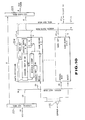
- Fig. 10 is a schematic of VCI compressor 204 of Fig. 8 and includes logical VCI register 221, VCI code register 223, CAM word 224, and logical AND gate 225.
- VCI code register 223. Two bits of logical VCI stored in logical VCI register 221 and directly becoming a VCI code are delivered intactly to VCI code register 223. The remaining 26 bits are all input to 64 CAM words 224.
- Each CAM word 224 compares an associative key stored therein with input data of 26 bits. If they match, it outputs associative data.
- the associative data of 6 bits is delivered to VCI code register 223 to become a VCI code together with the previous 2 bits. If the associative key and the input 26 bits do not match in any of CAM words 224, AND gate 225 outputs an error signal.
- FIG. 11 shows an E. 164 address/new VCI code conversion algorithm in E. 164 table 206 of FIG. 8.
- the device for performing the algorithm includes E. 164 address register 231 which stores E. 164 addresses, associative memories 232, 233 and VCI code register which stores a new VCI code.
- associative memories 232, 233 are used to obtain a new VCI code from the E. 164 address as in VCI compressor 204.
- the E. 164 address is of 60 bits, hierarchy is formed to suppress an increase in the hardware scale.
- the first 8 bits of 60 bits (15 figures) of the E. 164 address are fixed as a nation number, and the next 4 bits as a network identifier.
- the subsequent 48 bits indicative of the TC unit and subscriber number are divided into two hierarchies of 24 bits where the more significant 24 bits correspond to the most significant 3 bits of the new VCI code while the less significant 24 bits correspond to the least significant 5 bits of the new VCI code.
- the new VCI code is obtained from the E. 164 address.
- FIG. 12 is a block diagram illustrating the structure of user interfaces 21, 31 and 41 of the embodiment. It includes layer 1 processor (L1) 401, MAC control unit (MACC) 402, communication memory (CM) 403, processor 404, control bus interface 405, SAR layer handlers (SARH) 406, 407, and ATM exchange interface 408.
- L1 layer 1 processor
- MCC MAC control unit
- CM communication memory
- processor 404 control bus interface 405, SAR layer handlers (SARH) 406, 407, and ATM exchange interface 408.
- SARH SAR layer handlers
- Layer 1 processor 401 terminates layer 1.
- MAC control unit 402 stores MAC-PDU in communication memory 403 and interrupts processor 404, which filters the MAC address. If the address is of processor 404, it terminates up to the LLC layer and forms a CS-PDU from the N-PDU.
- processor 404 analyzes the network address in the network header, checks the destination LAN I/F and the E. 164 address thereof and adds them to the head of the CS header.
- Processor 404 reports the address stored in the CM of CS-PDU to SAR layer handler 406.
- Handler 406 converts CS-PDU into a cell. The resulting cells are outputted through ATM exchange interface 408 to the ATM exchange.
- SAR layer handler 407 The cells received through the switch bus are input to SAR layer handler 407 through ATM exchange interface 408.
- SAR layer handler 407 reassembles the cells to assemble a CS-PDU in communication memory 403.
- Handler 407 then interrupts processor 404, which then forms MAC-PDU from CS-PDU.
- destination MAC address is checked from the destination network address in the network header by means of the internal table or ARP of processor 404.
- Processor 404 reports the address stored in the CM of the MAC-PDU to MAC control unit 402, which then delivers a packet to the LAN through layer 1 processor 401.
Landscapes
- Engineering & Computer Science (AREA)
- Computer Networks & Wireless Communication (AREA)
- Signal Processing (AREA)
- Data Exchanges In Wide-Area Networks (AREA)
Claims (3)
- Kommunikationssteuerungssystem, das ein im Asynchrontransfermodus (ATM) betriebenes Netz (100) mit einer Vielzahl von zentralisierten ATM-Vermittlungsstellen (50, 60) und einer Vielzahl von verteilten ATM-Vermittlungsstellen (20, 30, 40) verwendet, die mit den zentralisierten ATM-Vermittlungsstellen über einen ATM-Übertragungspfad verbunden sind, mit:einer Vielzahl von verbindungslosen Dienstverarbeitungseinrichtungen (51, 61), die jeweils mit einer der zentralisierten ATM-Vermittlungsstellen verbunden sind:einer Vielzahl von Benutzerschnittstellen (21, 31. 41), die jeweils mit einer der verteilten ATM-Vermittlungsstellen verbunden sind; undeiner Vielzahl von Benutzervorrichtungen, die jeweils mit einer der Benutzerschnittstellen verbunden sind, zum Durchführen einer verbindungslosen Kommunikation über das ATM-Netz;wobei die Benutzerschnittstellen mit den verbindungslosen Dienstverarbeitungseinrichtungen über virtuelle Verbindungen verbunden sind und die verbindungslosen Dienstverarbeitungseinrichtungen untereinander über virtuelle Verbindungen verbunden sind;eine der Benutzerschnittstellen ein von einer der Benutzervorrichtungen ausgegebenes Datenpaket in eine ATM-Zelle umwandelt und die ATM-Zelle über die virtuellen Verbindungen an eine der verbindungslosen Dienstverarbeitungseinrichtungen überträgt; unddiese eine der verbindungslosen Dienstverarbeitungseinrichtungen die ATM-Zelle zu einer der virtuellen Verbindungen weiterleitet, die sich in einer Richtung befindet, in der eine Ziel-Benutzerschnittstelle vorhanden ist, um dadurch die Leitweglenkung der ATM-Zelle im ATM-Netz durchzuführen;dadurch gekennzeichnet, daß diese eine der Benutzerschnittstellen, nach Hinzufügen einer Zieladresse mit einer Datenlänge, die in einer SAR-Nutzlänge unterbringbar ist, zu einem Kopfabschnitt einer CS-PDU in einer CS-Unterschicht einer ATM-Anpassungsschicht, eine Segmentierung des von der einen der Benutzervorrichtungen ausgegebenen Datenpakets durchführt, um sie in eine BOM-Zelle, eine SSM-Zelle, eine COM-Zelle und eine EOM-Zelle der vier Segmenttypen von ATM-Zellen zu konvertieren, und sie an eine der verbindungslosen Dienstverarbeitungseinrichtungen überträgt; undwobei diese eine der verbindungslosen Dienstverarbeitungseinrichtungen durch Abfragen eines SAR-Kopfes der übertragenen ATM-Zelle, wenn ein Segmenttyp der übertragenen ATM-Zelle BOM oder SSM entspricht. auf der Grundlage der in der SAR-Nutzlänge gespeicherten Zieladresse eine der mit der Ziel-ßenutzerschnittstelle verbundenen virtuellen Verbindungen oder eine der virtuellen Verbindungen, die mit der verbindungslosen Dienstverarbeitungseinrichtung verbunden sind, die sich in der Richtung befindet, in der die Ziel-Benutzerschnittstelle vorhanden ist, wählt, einen Multiplex-Bezeichner MID im SAR-Kopf der ATM-Zelle in einen neuen Multiplex-Bezeichner MID, der in der gewählten virtuellen Verbindung einmalig ist, umwandelt und die ATM-Zelle zu der gewählten virtuellen Verbindung überträgt und außerdem die gewählte virtuelle Verbindung und den neuen Multiplex-Bezeichner MID, der auf der virtuellen Verbindung, über die die ATM-Zelle übertragen worden ist, und auf dem Multiplex-Bezeichner MID der übertragenen ATM-Zelle als Schlüsselinformationen beruht, speichert und, wenn der Segmenttyp der übertragenen ATM-Zelle COM oder EOM entspricht. die gewählte virtuelle Verbindung und den neuen Multiplex-Bezeichner MID, der auf der Grundlage der virtuellen Verbindung, über die die ATM-Zelle übertragen worden ist, und des MID der übertragenen ATM-Zelle als Schlüsselinformationen gespeichert wird, übernimmt, den Multiplex-Bezeichner MID im SAR-Kopf der ATM-Zelle in den neuen Multiplex-Bezeichner MID umwandelt und die ATM-Zelle zu der gewählten virtuellen Verbindung überträgt; wobei die verbindungslose Dienstverarbeitungseinrichtung ferner aufweist:eine E.164-Adreßtabelle zum Speichern. für jede E.164-Adresse, eines neuen virtuellen Wegbezeichners VPI und eines neuen virtuellen Verbindungsbezeichners VCI einer halbfesten virtuellen Verbindung. die sich in der Richtung befindet, in der die Ziel-Benutzerschnittstelle vorhanden ist;eine Leitwegtabelle. die für jeden neuen virtuellen Verbindungsbezeichner VCI vorhanden ist, zum Speichern des neuen virtuellen Wegbezeichners VPI, des neuen virtuellen Verbindungsbezeichners VCI und des neuen Multiplex-Bezeichners MID in Verbindung mit jedem Multiplex-Bezeichner MID;eine Vielzahl von MID-Zählern, die für jeden neuen virtuellen Verbindungsbezeichner VCI vorhanden sind;eine Einrichtung zum Durchsuchen der E.164-Adreßtabelle mit der E.164-Adresse als Schlüssel, um den neuen virtuellen Wegbezeichner VPI und den neuen virtuellen Verbindungsbezeichner VCI der halbfesten virtuellen Verbindung, die sich in der Richtung befindet, in der die Ziel-Benutzerschnittstelle vorhanden ist, zu ermitteln, und zum Überschreiben des neuen virtuellen Verbindungsbezeichners VCI und des neuen Multiplex-Bezeichners MID in der Leitwegtabelle mit dem ermittelten neuen virtuellen Wegbezeichner VPI und dem ermittelten neuen virtuellen Verbindungsbezeichner VCI;eine Einrichtung zum Wählen des MID-Zählers entsprechend dem neuen virtuellen Verbindungsbezeichner VCI, zum Übernehmen eines neuen Multiplex-Bezeichners MID durch Inkrementieren des MID-Zählers und zum Überschreiben des neuen Multiplex-Bezeichners MID in der Leitwegtabelle mit dem übernommenen neuen Multiplex-Bezeichner MID; undeine Einrichtung zum Überschreiben des virtuellen Wegbezeichners VPI, des virtuellen Verbindungsbezeichners VCI und des Multiplex-Bezeichners MID der eingegebenen ATM-Zelle mit dem neuen virtuellen Wegbezeichner VPI, dem neuen virtuellen Verbindungsbezeichner VCI und dem neuen Multiplex-Bezeichner MID, die in der Leitwegtabelle gespeichert sind, und zum Ausgeben der neu geschriebenen Bezeichner.
- Kommunikationssteuerungssystem nach Anspruch 1, wobei die eine der Benutzerschnittstellen eine Adresse der Ziel-Benutzerschnittstelle in der ATM-Zelle speichert. wenn sie das von der einen der Benutzervorrichtungen ausgegebene Datenpaket in die ATM-Zelle umwandelt, und wobei die eine der verbindungslosen Dienstverarbeitungseinrichtungen durch Abfragen einer in der ATM-Zelle gespeicherten Adresse der Ziel-Benutzerschnittstelle die ATM-Zelle zu einer der virtuellen Verbindungen weiterleitet, die sich in der Richtung befindet, in der die Ziel-Benutzerschnittstelle vorhanden ist, um somit die Leitweglenkung der ATM-Zelle durchzuführen.
- Kommunikationssteuerungssystem nach Anspruch 1 oder 2, wobei die eine der Benutzerschnittstellen die Segmentierung des von der einen der Benutzervorrichtungen ausgegebenen Datenpakets in Zellen einer vorbestimmten Länge durchführt, um eine Folge von ATM-Zellen zu bilden, eine Adresse der Ziel-Benutzerschnittstelle in einer führenden der Serie von ATM-Zellen speichert und die führende der ATM-Zellen über die virtuellen Verbindungen an eine der verbindungslosen Dienstverarbeitungseinrichtungen überträgt und wobei diese eine der verbindungslosen Dienstverarbeitungseinrichtungen, wenn sie die führende der ATM-Zellen empfängt, durch Abfrage der Adresse der Ziel-Benutzerschnittstelle, die in der führenden der ATM-Zellen gespeichert ist, eine der virtuellen Verbindungen auswählt, die zu der Ziel-Benutzerschnittstelle führen, um die führende der ATM-Zellen zu der gewählten virtuellen Verbindung weiterzuleiten, um dadurch die Leitweglenkung durchzuführen und, wenn sie eine andere ATM-Zelle als die führende der ATM-Zellen empfängt, diese eine ATM-Zelle an die gewählte virtuelle Verbindung weiterleitet, um dadurch das Routing durchzuführen.
Applications Claiming Priority (2)
| Application Number | Priority Date | Filing Date | Title |
|---|---|---|---|
| JP2261700A JPH04138739A (ja) | 1990-09-28 | 1990-09-28 | 非同期伝送モード網を用いた通信制御方式 |
| JP261700/90 | 1990-09-28 |
Publications (2)
| Publication Number | Publication Date |
|---|---|
| EP0482773A1 EP0482773A1 (de) | 1992-04-29 |
| EP0482773B1 true EP0482773B1 (de) | 1997-01-08 |
Family
ID=17365501
Family Applications (1)
| Application Number | Title | Priority Date | Filing Date |
|---|---|---|---|
| EP91308883A Expired - Lifetime EP0482773B1 (de) | 1990-09-28 | 1991-09-27 | Kommunikationssteuerungssystem in einem asynchronen Zeitvielfachübermittlungsnetz (ATM) |
Country Status (6)
| Country | Link |
|---|---|
| US (1) | US5280476A (de) |
| EP (1) | EP0482773B1 (de) |
| JP (1) | JPH04138739A (de) |
| KR (1) | KR950002270B1 (de) |
| CA (1) | CA2052349C (de) |
| DE (1) | DE69124060T2 (de) |
Cited By (3)
| Publication number | Priority date | Publication date | Assignee | Title |
|---|---|---|---|---|
| US6366586B1 (en) | 1994-05-05 | 2002-04-02 | Sprint Communications Company L.P. | Method, system and apparatus for telecommunications control |
| US6633561B2 (en) | 1994-05-05 | 2003-10-14 | Sprint Communications Company, L.P. | Method, system and apparatus for telecommunications control |
| US6704327B1 (en) | 1997-05-09 | 2004-03-09 | Sprint Communications Company, L.P. | System and method for connecting a call |
Families Citing this family (104)
| Publication number | Priority date | Publication date | Assignee | Title |
|---|---|---|---|---|
| AU661988B2 (en) * | 1991-01-31 | 1995-08-17 | Fujitsu Limited | Connectionless communication system |
| US5809012A (en) * | 1991-01-31 | 1998-09-15 | Fujitsu Limited | Connectionless communication system |
| US20020101871A1 (en) * | 1991-01-31 | 2002-08-01 | Fujitsu Limited | Connectionless communication system |
| JP3262142B2 (ja) * | 1992-01-16 | 2002-03-04 | 富士通株式会社 | Atmセル化装置、atmセル化方法、ノード、及びノードにおける多重化方法 |
| US5357510A (en) * | 1992-02-19 | 1994-10-18 | Fujitsu Limited | Apparatus and a method for supervising and controlling ATM traffic |
| EP0584687A3 (en) * | 1992-08-21 | 1996-01-24 | Ascom Tech Ag | Apparatus for digital data transmission between two subscribers |
| US5444702A (en) * | 1992-09-14 | 1995-08-22 | Network Equipment Technologies, Inc. | Virtual network using asynchronous transfer mode |
| DE4306186A1 (de) * | 1993-02-27 | 1994-09-01 | Philips Patentverwaltung | Lokales, nach dem asynchronen Transfermodus (ATM) arbeitendes Netzwerk |
| JPH06318945A (ja) * | 1993-05-07 | 1994-11-15 | Sharp Corp | ネットワーク間相互接続装置 |
| US5386412A (en) * | 1993-05-11 | 1995-01-31 | Park; Jung S. | Telecommunication system protocol for asynchronous data communication between multiport switch control processor and information support personal computer terminal |
| JP2546505B2 (ja) * | 1993-06-23 | 1996-10-23 | 日本電気株式会社 | Cladにおけるアドレス学習装置 |
| EP0649234B1 (de) * | 1993-10-14 | 2001-09-19 | International Business Machines Corporation | Verfahren und Einrichtung zum Datentransfer in ein ATM-Netz |
| US5864554A (en) * | 1993-10-20 | 1999-01-26 | Lsi Logic Corporation | Multi-port network adapter |
| US5446726A (en) * | 1993-10-20 | 1995-08-29 | Lsi Logic Corporation | Error detection and correction apparatus for an asynchronous transfer mode (ATM) network device |
| US5872784A (en) * | 1993-10-20 | 1999-02-16 | Lsi Logic Corporation | High speed single chip digital video network apparatus |
| US5914955A (en) * | 1993-10-20 | 1999-06-22 | Lsi Logic Corporation | Switched network hub on a chip |
| US5414707A (en) * | 1993-12-01 | 1995-05-09 | Bell Communications Research, Inc. | Broadband ISDN processing method and system |
| JPH07162435A (ja) * | 1993-12-06 | 1995-06-23 | Fujitsu Ltd | 半固定パス確認方法および装置 |
| JP3142433B2 (ja) * | 1993-12-29 | 2001-03-07 | 株式会社東芝 | ブリッジ装置及びブリッジ接続方法 |
| US5467342A (en) * | 1994-01-12 | 1995-11-14 | Scientific-Atlanta, Inc. | Methods and apparatus for time stamp correction in an asynchronous transfer mode network |
| US5528592A (en) * | 1994-01-27 | 1996-06-18 | Dsc Communications Corporation | Method and apparatus for route processing asynchronous transfer mode cells |
| US5469433A (en) * | 1994-04-29 | 1995-11-21 | Bell Communications Research, Inc. | System for the parallel assembly of data transmissions in a broadband network |
| US5703876A (en) * | 1994-05-05 | 1997-12-30 | Christie; Joseph Michael | ATM transport system |
| JPH07307738A (ja) * | 1994-05-13 | 1995-11-21 | Mitsubishi Electric Corp | プロトコル処理装置 |
| US5555244A (en) * | 1994-05-19 | 1996-09-10 | Integrated Network Corporation | Scalable multimedia network |
| SE514978C2 (sv) * | 1994-07-11 | 2001-05-28 | Telia Ab | Anordning för anslutning av ATM-terminaler och/eller LAN- terminaler till ett ATM-baserat nät |
| US5483526A (en) * | 1994-07-20 | 1996-01-09 | Digital Equipment Corporation | Resynchronization method and apparatus for local memory buffers management for an ATM adapter implementing credit based flow control |
| JP2682459B2 (ja) * | 1994-08-23 | 1997-11-26 | 日本電気株式会社 | 通信制御装置 |
| US5583859A (en) * | 1994-08-30 | 1996-12-10 | Bell Communications Research, Inc. | Data labeling technique for high performance protocol processing |
| JP3224963B2 (ja) * | 1994-08-31 | 2001-11-05 | 株式会社東芝 | ネットワーク接続装置及びパケット転送方法 |
| US5548587A (en) * | 1994-09-12 | 1996-08-20 | Efficient Networks, Inc. | Asynchronous transfer mode adapter for desktop applications |
| EP0702474A1 (de) * | 1994-09-19 | 1996-03-20 | International Business Machines Corporation | Dynamisch strukturierter Datenübertragungsmechanismus in einem ATM-Netzwerk |
| US5490140A (en) * | 1994-09-30 | 1996-02-06 | International Business Machines Corporation | System and method for providing ATM support for frame relay DTEs with a terminal adapter |
| US5490141A (en) * | 1994-09-30 | 1996-02-06 | International Business Machines Corporation | System and method for providing SVC service through an ATM network for frame relay DTEs with a terminal adapter |
| US5590122A (en) * | 1994-12-22 | 1996-12-31 | Emc Corporation | Method and apparatus for reordering frames |
| JP3014080B2 (ja) * | 1994-12-28 | 2000-02-28 | 三菱電機株式会社 | 交換機アダプタ及び汎用計算機 |
| US5546390A (en) * | 1994-12-29 | 1996-08-13 | Storage Technology Corporation | Method and apparatus for radix decision packet processing |
| US5566170A (en) * | 1994-12-29 | 1996-10-15 | Storage Technology Corporation | Method and apparatus for accelerated packet forwarding |
| US5550816A (en) * | 1994-12-29 | 1996-08-27 | Storage Technology Corporation | Method and apparatus for virtual switching |
| US5598410A (en) * | 1994-12-29 | 1997-01-28 | Storage Technology Corporation | Method and apparatus for accelerated packet processing |
| US5930255A (en) * | 1995-01-31 | 1999-07-27 | Canon Kabushiki Kaisha | Method of setting a relaying path in a communication network |
| US7468977B1 (en) * | 1995-07-12 | 2008-12-23 | Nortel Networks Limited | LAN/ATM switch having local packet switching and an ATM core fabric |
| US6041166A (en) | 1995-07-14 | 2000-03-21 | 3Com Corp. | Virtual network architecture for connectionless LAN backbone |
| US6005864A (en) * | 1995-07-14 | 1999-12-21 | 3Com Corporation | Protocol for optimized multicast services for a connection oriented network providing lan emulation |
| US5752003A (en) * | 1995-07-14 | 1998-05-12 | 3 Com Corporation | Architecture for managing traffic in a virtual LAN environment |
| US5920560A (en) * | 1995-08-23 | 1999-07-06 | Fujitsu Limited | Multi-connection management method and apparatus for switch system |
| KR100362586B1 (ko) * | 1995-12-28 | 2003-02-14 | 삼성전자 주식회사 | 비연결 서버 이중화 구현 장치 |
| DE19604245C2 (de) * | 1996-02-06 | 2000-07-06 | Siemens Ag | Verfahren zum Übertragen von Zeitmultiplexkanalform-Digitalsignalen über eine ATM-Übertragungseinrichtung |
| US6178169B1 (en) | 1996-03-28 | 2001-01-23 | British Telecommunications Public Limited Company | Method of transmitting an ATM cell over an ATM network |
| US5757796A (en) * | 1996-04-26 | 1998-05-26 | Cascade Communications Corp. | ATM address translation method and apparatus |
| US5991867A (en) * | 1996-09-12 | 1999-11-23 | Efficient Networks, Inc. | Transmit scheduler for an asynchronous transfer mode network and method of operation |
| US6085250A (en) * | 1997-03-20 | 2000-07-04 | Efficient Networks, Inc. | Method and system for using layered networking application program interfaces (APIs) using a native asynchronous transfer mode (ATM) API |
| US6084881A (en) * | 1997-05-22 | 2000-07-04 | Efficient Networks, Inc. | Multiple mode xDSL interface |
| KR100247837B1 (ko) | 1997-06-11 | 2000-04-01 | 윤종용 | 협대역 종합정보통신망의 트래픽 처리가 가능한 에이티엠 스위치장치 및 방법 |
| US5951707A (en) * | 1997-06-27 | 1999-09-14 | International Business Machines Corporation | Method of partitioning CRC calculation for a low-cost ATM adapter |
| JP3042457B2 (ja) | 1997-08-21 | 2000-05-15 | 日本電気株式会社 | マルチレイヤatm通信装置 |
| US6032190A (en) * | 1997-10-03 | 2000-02-29 | Ascend Communications, Inc. | System and method for processing data packets |
| KR100283073B1 (ko) * | 1997-10-13 | 2001-03-02 | 정선종 | 이동통신시스템에서매체액세스제어프레임구조를이용한제어평면정보송수신방법 |
| JP3511875B2 (ja) * | 1998-01-13 | 2004-03-29 | 横河電機株式会社 | 通信制御システム |
| US6256308B1 (en) * | 1998-01-20 | 2001-07-03 | Telefonaktiebolaget Lm Ericsson | Multi-service circuit for telecommunications |
| US6188691B1 (en) | 1998-03-16 | 2001-02-13 | 3Com Corporation | Multicast domain virtual local area network |
| JP3233208B2 (ja) | 1998-04-30 | 2001-11-26 | 日本電気株式会社 | レイヤ3フロースイッチング方法 |
| US6201792B1 (en) | 1998-05-14 | 2001-03-13 | 3Com Corporation | Backpressure responsive multicast queue |
| US6223149B1 (en) | 1998-05-28 | 2001-04-24 | 3Com Corporation | Non-distributed LAN emulation server redundancy method |
| US6269076B1 (en) | 1998-05-28 | 2001-07-31 | 3Com Corporation | Method of resolving split virtual LANs utilizing a network management system |
| US6289017B1 (en) | 1998-05-29 | 2001-09-11 | 3Com Corporation | Method of providing redundancy and load sharing among multiple LECs in an asynchronous mode network |
| JP3537318B2 (ja) | 1998-07-24 | 2004-06-14 | 富士通株式会社 | 特定のコネクションの通信データを加工する交換機および交換方法 |
| US6657961B1 (en) | 1998-08-18 | 2003-12-02 | Efficient Networks, Inc. | System and method for enhanced end station to end station data flow control |
| KR100640908B1 (ko) | 1998-10-01 | 2007-01-31 | 엘지전자 주식회사 | 이동통신 시스템에서의 트랜스포트 포맷 설정 방법 및 송신 장치 |
| KR100619598B1 (ko) * | 1998-10-01 | 2006-12-01 | 엘지전자 주식회사 | 이동통신시스템에서의 신호 포맷방법 |
| FI106504B (fi) * | 1998-10-06 | 2001-02-15 | Nokia Networks Oy | Datan segmentointimenetelmä tietoliikennejärjestelmässä |
| US6480891B1 (en) | 1999-01-04 | 2002-11-12 | 3Com Corporation | Embedded code memory size reduction in asynchronous mode transfer devices |
| US6532237B1 (en) | 1999-02-16 | 2003-03-11 | 3Com Corporation | Apparatus for and method of testing a hierarchical PNNI based ATM network |
| US6661774B1 (en) | 1999-02-16 | 2003-12-09 | Efficient Networks, Inc. | System and method for traffic shaping packet-based signals |
| US6590897B1 (en) | 1999-03-08 | 2003-07-08 | Efficient Networks, Inc. | System and method for bridging universal serial bus and asynchronous transfer mode communication links |
| US6487171B1 (en) | 1999-05-19 | 2002-11-26 | 3Com Corporation | Crossbar switching matrix with broadcast buffering |
| US6470022B1 (en) | 1999-05-19 | 2002-10-22 | 3Com Corporation | Method of distributing network resources fairly between users in an asynchronous transfer mode network |
| US6539019B1 (en) | 1999-05-24 | 2003-03-25 | 3Com Corporation | Methods and apparatus for automatically connecting a dynamic host configuration protocol (DHCP) client network device to a virtual local area network (VLAN) |
| US6580693B1 (en) | 1999-05-24 | 2003-06-17 | 3Com Corporation | Methods and apparatus for detecting leaks in ATM networks |
| US6574232B1 (en) | 1999-05-26 | 2003-06-03 | 3Com Corporation | Crossbar switch utilizing broadcast buffer and associated broadcast buffer management unit |
| US6614792B1 (en) | 1999-05-27 | 2003-09-02 | 3Com Corporation | Proxy MPC for providing MPOA services to legacy lane clients in an asynchronous transfer mode network |
| DE19926959C1 (de) * | 1999-06-14 | 2001-02-01 | Siemens Ag | ATM Vermittlungseinrichtung mit einem Koppelnetz |
| US6721323B1 (en) | 1999-06-14 | 2004-04-13 | Tellab Operations, Inc. | Distributed virtual path |
| US6526034B1 (en) | 1999-09-21 | 2003-02-25 | Tantivy Communications, Inc. | Dual mode subscriber unit for short range, high rate and long range, lower rate data communications |
| US6681364B1 (en) | 1999-09-24 | 2004-01-20 | International Business Machines Corporation | Cyclic redundancy check for partitioned frames |
| WO2002017570A1 (en) * | 2000-08-24 | 2002-02-28 | Ocular Networks | Unified data packet for encapsulating data packets having diverse formats |
| US7386621B1 (en) | 2000-08-31 | 2008-06-10 | Sharp Laboratories Of America, Inc. | Efficient and reliable transmission via a hybrid broadcast-point-to-point system |
| US7069557B2 (en) * | 2002-05-23 | 2006-06-27 | International Business Machines Corporation | Network processor which defines virtual paths without using logical path descriptors |
| US8842657B2 (en) * | 2003-10-15 | 2014-09-23 | Qualcomm Incorporated | High speed media access control with legacy system interoperability |
| US9226308B2 (en) | 2003-10-15 | 2015-12-29 | Qualcomm Incorporated | Method, apparatus, and system for medium access control |
| US8233462B2 (en) | 2003-10-15 | 2012-07-31 | Qualcomm Incorporated | High speed media access control and direct link protocol |
| US8483105B2 (en) * | 2003-10-15 | 2013-07-09 | Qualcomm Incorporated | High speed media access control |
| US8472473B2 (en) * | 2003-10-15 | 2013-06-25 | Qualcomm Incorporated | Wireless LAN protocol stack |
| US8284752B2 (en) * | 2003-10-15 | 2012-10-09 | Qualcomm Incorporated | Method, apparatus, and system for medium access control |
| US8462817B2 (en) * | 2003-10-15 | 2013-06-11 | Qualcomm Incorporated | Method, apparatus, and system for multiplexing protocol data units |
| US8903440B2 (en) * | 2004-01-29 | 2014-12-02 | Qualcomm Incorporated | Distributed hierarchical scheduling in an ad hoc network |
| US8315271B2 (en) * | 2004-03-26 | 2012-11-20 | Qualcomm Incorporated | Method and apparatus for an ad-hoc wireless communications system |
| US20050220091A1 (en) * | 2004-03-31 | 2005-10-06 | Lavigne Bruce E | Secure remote mirroring |
| US7564814B2 (en) * | 2004-05-07 | 2009-07-21 | Qualcomm, Incorporated | Transmission mode and rate selection for a wireless communication system |
| US8401018B2 (en) * | 2004-06-02 | 2013-03-19 | Qualcomm Incorporated | Method and apparatus for scheduling in a wireless network |
| CN100338927C (zh) * | 2004-09-09 | 2007-09-19 | 毛德操 | 通过扩展IPv4包头实现在互联网中按路径寻址和路由的方法 |
| US8179902B2 (en) * | 2005-07-15 | 2012-05-15 | Cisco Technology, Inc. | Method and system for automatic generation of route distinguishers for virtual private networks |
| US8600336B2 (en) | 2005-09-12 | 2013-12-03 | Qualcomm Incorporated | Scheduling with reverse direction grant in wireless communication systems |
| KR100981498B1 (ko) * | 2006-01-18 | 2010-09-10 | 삼성전자주식회사 | 무선 통신 시스템에서 버스트 처리장치 및 방법 |
Family Cites Families (3)
| Publication number | Priority date | Publication date | Assignee | Title |
|---|---|---|---|---|
| US4787082A (en) * | 1986-07-24 | 1988-11-22 | American Telephone And Telegraph Company, At&T Bell Laboratories | Data flow control arrangement for local area network |
| JP2550642B2 (ja) * | 1988-03-04 | 1996-11-06 | 日本電気株式会社 | パケットフレーム伝送方式 |
| EP0331190B1 (de) * | 1988-03-04 | 1996-01-03 | Nec Corporation | Verfahren zur Steuerung der Adressenparameter zur Verbindung zwischen LAN- und ISDN-Systemen |
-
1990
- 1990-09-28 JP JP2261700A patent/JPH04138739A/ja active Pending
-
1991
- 1991-09-26 US US07/765,970 patent/US5280476A/en not_active Expired - Fee Related
- 1991-09-27 EP EP91308883A patent/EP0482773B1/de not_active Expired - Lifetime
- 1991-09-27 CA CA002052349A patent/CA2052349C/en not_active Expired - Fee Related
- 1991-09-27 DE DE69124060T patent/DE69124060T2/de not_active Expired - Fee Related
- 1991-09-28 KR KR1019910016971A patent/KR950002270B1/ko not_active Expired - Fee Related
Cited By (6)
| Publication number | Priority date | Publication date | Assignee | Title |
|---|---|---|---|---|
| US6366586B1 (en) | 1994-05-05 | 2002-04-02 | Sprint Communications Company L.P. | Method, system and apparatus for telecommunications control |
| US6424652B1 (en) | 1994-05-05 | 2002-07-23 | Sprint Communications Company, L.P. | Method, system and apparatus for telecommunications control |
| US6463052B1 (en) | 1994-05-05 | 2002-10-08 | Sprint Communications Company L.P. | Method, system and apparatus for telecommunications control |
| US6633561B2 (en) | 1994-05-05 | 2003-10-14 | Sprint Communications Company, L.P. | Method, system and apparatus for telecommunications control |
| US6643282B1 (en) | 1994-05-05 | 2003-11-04 | Sprint Communications Company L.P. | Method, system and apparatus for telecommunications control |
| US6704327B1 (en) | 1997-05-09 | 2004-03-09 | Sprint Communications Company, L.P. | System and method for connecting a call |
Also Published As
| Publication number | Publication date |
|---|---|
| US5280476A (en) | 1994-01-18 |
| CA2052349A1 (en) | 1992-03-29 |
| JPH04138739A (ja) | 1992-05-13 |
| CA2052349C (en) | 1998-08-25 |
| EP0482773A1 (de) | 1992-04-29 |
| KR950002270B1 (ko) | 1995-03-15 |
| DE69124060D1 (de) | 1997-02-20 |
| DE69124060T2 (de) | 1997-06-05 |
Similar Documents
| Publication | Publication Date | Title |
|---|---|---|
| EP0482773B1 (de) | Kommunikationssteuerungssystem in einem asynchronen Zeitvielfachübermittlungsnetz (ATM) | |
| US5452296A (en) | Asynchronous transfer mode communication system | |
| US5774675A (en) | Header converting method | |
| US4975906A (en) | Network system | |
| US6064674A (en) | Method and apparatus for hardware forwarding of LAN frames over ATM networks | |
| JP2980032B2 (ja) | コネクションレスデータ通信方式 | |
| US5701300A (en) | Connectionless server for an asynchronous transfer mode network | |
| JP3129244B2 (ja) | 通信制御装置 | |
| JPH06335079A (ja) | Atm網におけるセル多重化装置 | |
| JPH10224379A (ja) | Atm再構成コントローラおよび再構成方法 | |
| US20040090987A1 (en) | Method and apparatus for hardware forwarding of LAN frames over ATM networks | |
| US5495478A (en) | Apparatus and method for processing asynchronous transfer mode cells | |
| JP2836606B2 (ja) | Atmセル転送装置 | |
| WO1995014269A1 (en) | A high-performance host interface for networks carrying connectionless traffic | |
| US7215676B2 (en) | Method of converting ATM cells in ATM network system | |
| US7310310B1 (en) | Multi-link SAR for bonding ATM cell-streams | |
| US7158523B2 (en) | Multi-link segmentation and reassembly sublayer for bonding asynchronous transfer mode permanent virtual circuits | |
| JPH07221762A (ja) | パケット処理方法および通信インターフェイス装置 | |
| Chao et al. | A shared‐memory virtual channel queue for ATM broadband terminal adaptors | |
| JPH05268241A (ja) | Atm交換におけるヘッダの変換方式 | |
| US6301259B1 (en) | Switch and switching method | |
| EP0941592B1 (de) | Wegesuche für pakete in einem fernmeldesystem | |
| JPH09205439A (ja) | Atmコントローラおよび、atm通信制御装置 | |
| Chao et al. | Design of virtual channel queue in an ATM broadband terminal adaptor | |
| KR0129179B1 (ko) | Sscop부계층에서 pdu 해석회로 |
Legal Events
| Date | Code | Title | Description |
|---|---|---|---|
| PUAI | Public reference made under article 153(3) epc to a published international application that has entered the european phase |
Free format text: ORIGINAL CODE: 0009012 |
|
| 17P | Request for examination filed |
Effective date: 19911021 |
|
| AK | Designated contracting states |
Kind code of ref document: A1 Designated state(s): DE FR GB |
|
| 17Q | First examination report despatched |
Effective date: 19940429 |
|
| GRAG | Despatch of communication of intention to grant |
Free format text: ORIGINAL CODE: EPIDOS AGRA |
|
| GRAH | Despatch of communication of intention to grant a patent |
Free format text: ORIGINAL CODE: EPIDOS IGRA |
|
| GRAH | Despatch of communication of intention to grant a patent |
Free format text: ORIGINAL CODE: EPIDOS IGRA |
|
| GRAA | (expected) grant |
Free format text: ORIGINAL CODE: 0009210 |
|
| AK | Designated contracting states |
Kind code of ref document: B1 Designated state(s): DE FR GB |
|
| REF | Corresponds to: |
Ref document number: 69124060 Country of ref document: DE Date of ref document: 19970220 |
|
| ET | Fr: translation filed | ||
| PLBE | No opposition filed within time limit |
Free format text: ORIGINAL CODE: 0009261 |
|
| STAA | Information on the status of an ep patent application or granted ep patent |
Free format text: STATUS: NO OPPOSITION FILED WITHIN TIME LIMIT |
|
| 26N | No opposition filed | ||
| REG | Reference to a national code |
Ref country code: GB Ref legal event code: 746 Effective date: 19980915 |
|
| REG | Reference to a national code |
Ref country code: FR Ref legal event code: D6 |
|
| REG | Reference to a national code |
Ref country code: GB Ref legal event code: IF02 |
|
| PGFP | Annual fee paid to national office [announced via postgrant information from national office to epo] |
Ref country code: FR Payment date: 20020910 Year of fee payment: 12 |
|
| PGFP | Annual fee paid to national office [announced via postgrant information from national office to epo] |
Ref country code: GB Payment date: 20020925 Year of fee payment: 12 |
|
| PGFP | Annual fee paid to national office [announced via postgrant information from national office to epo] |
Ref country code: DE Payment date: 20021002 Year of fee payment: 12 |
|
| PG25 | Lapsed in a contracting state [announced via postgrant information from national office to epo] |
Ref country code: GB Free format text: LAPSE BECAUSE OF NON-PAYMENT OF DUE FEES Effective date: 20030927 |
|
| PG25 | Lapsed in a contracting state [announced via postgrant information from national office to epo] |
Ref country code: DE Free format text: LAPSE BECAUSE OF NON-PAYMENT OF DUE FEES Effective date: 20040401 |
|
| GBPC | Gb: european patent ceased through non-payment of renewal fee |
Effective date: 20030927 |
|
| PG25 | Lapsed in a contracting state [announced via postgrant information from national office to epo] |
Ref country code: FR Free format text: LAPSE BECAUSE OF NON-PAYMENT OF DUE FEES Effective date: 20040528 |
|
| REG | Reference to a national code |
Ref country code: FR Ref legal event code: ST |