EP0482840B1 - Hybrider dampfgekühlter Energieanschluss für einen Kryostat - Google Patents
Hybrider dampfgekühlter Energieanschluss für einen Kryostat Download PDFInfo
- Publication number
- EP0482840B1 EP0482840B1 EP91309644A EP91309644A EP0482840B1 EP 0482840 B1 EP0482840 B1 EP 0482840B1 EP 91309644 A EP91309644 A EP 91309644A EP 91309644 A EP91309644 A EP 91309644A EP 0482840 B1 EP0482840 B1 EP 0482840B1
- Authority
- EP
- European Patent Office
- Prior art keywords
- cryogen
- conductor
- vapor
- power lead
- conductor members
- Prior art date
- Legal status (The legal status is an assumption and is not a legal conclusion. Google has not performed a legal analysis and makes no representation as to the accuracy of the status listed.)
- Expired - Lifetime
Links
Images


Classifications
-
- H—ELECTRICITY
- H02—GENERATION; CONVERSION OR DISTRIBUTION OF ELECTRIC POWER
- H02G—INSTALLATION OF ELECTRIC CABLES OR LINES, OR OF COMBINED OPTICAL AND ELECTRIC CABLES OR LINES
- H02G15/00—Cable fittings
- H02G15/34—Cable fittings for cryogenic cables
-
- F—MECHANICAL ENGINEERING; LIGHTING; HEATING; WEAPONS; BLASTING
- F17—STORING OR DISTRIBUTING GASES OR LIQUIDS
- F17C—VESSELS FOR CONTAINING OR STORING COMPRESSED, LIQUEFIED OR SOLIDIFIED GASES; FIXED-CAPACITY GAS-HOLDERS; FILLING VESSELS WITH, OR DISCHARGING FROM VESSELS, COMPRESSED, LIQUEFIED, OR SOLIDIFIED GASES
- F17C13/00—Details of vessels or of the filling or discharging of vessels
- F17C13/005—Details of vessels or of the filling or discharging of vessels for medium-size and small storage vessels not under pressure
- F17C13/006—Details of vessels or of the filling or discharging of vessels for medium-size and small storage vessels not under pressure for Dewar vessels or cryostats
-
- F—MECHANICAL ENGINEERING; LIGHTING; HEATING; WEAPONS; BLASTING
- F17—STORING OR DISTRIBUTING GASES OR LIQUIDS
- F17C—VESSELS FOR CONTAINING OR STORING COMPRESSED, LIQUEFIED OR SOLIDIFIED GASES; FIXED-CAPACITY GAS-HOLDERS; FILLING VESSELS WITH, OR DISCHARGING FROM VESSELS, COMPRESSED, LIQUEFIED, OR SOLIDIFIED GASES
- F17C2221/00—Handled fluid, in particular type of fluid
- F17C2221/01—Pure fluids
- F17C2221/016—Noble gases (Ar, Kr, Xe)
- F17C2221/017—Helium
-
- F—MECHANICAL ENGINEERING; LIGHTING; HEATING; WEAPONS; BLASTING
- F17—STORING OR DISTRIBUTING GASES OR LIQUIDS
- F17C—VESSELS FOR CONTAINING OR STORING COMPRESSED, LIQUEFIED OR SOLIDIFIED GASES; FIXED-CAPACITY GAS-HOLDERS; FILLING VESSELS WITH, OR DISCHARGING FROM VESSELS, COMPRESSED, LIQUEFIED, OR SOLIDIFIED GASES
- F17C2223/00—Handled fluid before transfer, i.e. state of fluid when stored in the vessel or before transfer from the vessel
- F17C2223/01—Handled fluid before transfer, i.e. state of fluid when stored in the vessel or before transfer from the vessel characterised by the phase
- F17C2223/0146—Two-phase
- F17C2223/0153—Liquefied gas, e.g. LPG, GPL
- F17C2223/0161—Liquefied gas, e.g. LPG, GPL cryogenic, e.g. LNG, GNL, PLNG
-
- F—MECHANICAL ENGINEERING; LIGHTING; HEATING; WEAPONS; BLASTING
- F17—STORING OR DISTRIBUTING GASES OR LIQUIDS
- F17C—VESSELS FOR CONTAINING OR STORING COMPRESSED, LIQUEFIED OR SOLIDIFIED GASES; FIXED-CAPACITY GAS-HOLDERS; FILLING VESSELS WITH, OR DISCHARGING FROM VESSELS, COMPRESSED, LIQUEFIED, OR SOLIDIFIED GASES
- F17C2227/00—Transfer of fluids, i.e. method or means for transferring the fluid; Heat exchange with the fluid
- F17C2227/03—Heat exchange with the fluid
- F17C2227/0302—Heat exchange with the fluid by heating
-
- Y—GENERAL TAGGING OF NEW TECHNOLOGICAL DEVELOPMENTS; GENERAL TAGGING OF CROSS-SECTIONAL TECHNOLOGIES SPANNING OVER SEVERAL SECTIONS OF THE IPC; TECHNICAL SUBJECTS COVERED BY FORMER USPC CROSS-REFERENCE ART COLLECTIONS [XRACs] AND DIGESTS
- Y02—TECHNOLOGIES OR APPLICATIONS FOR MITIGATION OR ADAPTATION AGAINST CLIMATE CHANGE
- Y02E—REDUCTION OF GREENHOUSE GAS [GHG] EMISSIONS, RELATED TO ENERGY GENERATION, TRANSMISSION OR DISTRIBUTION
- Y02E40/00—Technologies for an efficient electrical power generation, transmission or distribution
- Y02E40/60—Superconducting electric elements or equipment; Power systems integrating superconducting elements or equipment
Definitions
- This invention relates to electric leads for transmission of electrical power into or out of a cryostat, and in particular it relates to such power leads which are cooled by cryogen vapor.
- a power lead is known, for example, from US-A- 3 849 589.
- Devices utilizing conventional superconducting materials must be operated at very low temperatures, usually very close to absolute zero.
- the device is typically immersed in a liquid cryogen contained within a cryostat.
- Helium which has a boiling point of about 4K, is commonly used as the cryogen.
- Interfacing is required for carrying current to and from the device as well as for monitoring controls or instrumentation in the cryostat.
- Instrumentation leads typically carry very low current and are dimensionally very small so that heat leak into the cryostat along these leads is not a major concern.
- the transmission of relatively large amounts of current as would occur, for instance, in superconducting magnet applications requires that power leads be designed to minimize heat leakage into the cryostat.
- the method for accomplishing this is to build power leads that are internally vapor cooled by the vapor that is boiled off from the heat leakage.
- These leads typically comprise a cylindrical metal tube containing many hollow conductors, such as braided cooper sleeves, through which the vapor passes. This geometry presents a large amount of surface area per unit volume of conductor and results in efficient transfer of heat to the vapor.
- These leads can be optimized for a minimum heat leak by sizing the length and conduction area so that the heat leak into the lead at the warm end is zero. An example of this is discussed in, for example, G.
- a power lead for a cryostat which includes a first conductor section having conductor members made of a material which is superconducting at a temperature intermediate ambient temperature and the temperature of the cryogen used in the internal chamber of the cryostat.
- This superconductor section extends inward toward the pool of liquid cryogen in the cryostat and outward to an intermediate point which remains below the intermediate temperature at which the material becomes superconducting.
- a second conductor section having conductors which remain normal conductors above the intermediate temperature extend outward from the superconductor members to outside the cryostat. Since the conductors of the first section are superconducting, they generate no Joule heating.
- Joule heating is only produced in the normal conductor in the second outer section of the power lead.
- a flow of cryogen vapor is maintained over the conductors of the power lead to maintain the conductors of the first section superconducting and to remove heat from the normal conductors of the second section.
- a tubular enclosure surrounding the conductors and vented to atmosphere produces an efficient flow of cooling cryogen vapor.
- the superconducting members are supported at opposite ends by collector plates.
- the superconductors are soldered to one collector plate and connected to the other, preferably the upper collector plate, by a flexible connector to allow for differences in thermal expansion of the individual superconducting members.
- the superconducting members are maintained below the critical temperature and the normal conductors are cooled just by vapor of the cryogen in the cryostat.
- the tubular enclosure around the normal conductors comprises a single tubular member which guides cryogen vapor from the superconducting section over the normal conductors and out through the vent.
- the superconducting members are maintained below their critical temperature by vapor of the primary cryogen in the cryostat while the normal conductors are cooled principally by a secondary cryogen with help by vapor from the primary cryogen.
- the upper section of the tubular enclosure in this embodiment of the power lead includes an inner tubular member surrounding the normal conductors and a concentric outer tubular member forming an annular passage with the inner tubular member. Vapor of the primary cryogen passes over the superconducting members through the upper collector plate, into the annular passage and then out through a primary cryogen vent.
- the inner tube forms a separate chamber surrounding the normal conductors into which is introduced a pool of the secondary cryogen.
- This secondary cryogen vaporizes with the vapor passing upward around the normal conductors and out through a separate vent.
- the inner tube is made of a material with high thermal conductivity so that part of the heat load from the normal conductors is taken by the vapor of the primary cryogen which flows around the inner tube.
- the outer tube of the upper section and the tube surrounding the superconducting section are made of thermally and electrically insulating material.
- helium is used as the primary cryogen and nitrogen as the secondary cryogen.
- FIGS. 1A and 1B when placed end to end form a longitudinal sectional view of a cryostat power lead in accordance with one embodiment of the invention.
- Figure 2 is a fragmentary view in enlarged scale of a portion of Figure 1.
- Figure 3 is a transverse section through the power lead of Figure 1 taken along line III-III.
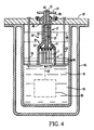
- Figure 4 is a vertical section through a second embodiment of a power lead in accordance with the invention shown mounted in a cryostat.
- a power lead 1 for a cryostat in accordance with the invention includes a superconducting section 3 and a normal conducting section 5.
- the superconducting section 3 includes a number of superconducting members 7.
- These superconducting members 7 are made of what is referred to as high temperature superconducting (HTSC) materials.
- HTSC materials are newly developed materials having a critical temperature (below which they are superconducting) which is substantially above the near absolute zero critical temperature for conventional superconducting materials.
- HTSC materials include many ceramic materials.
- a suitable HTSC material for the superconducting members 7 is yttrium barium copper oxide (YBCO) which has a critical temperature of about 90K.
- YBCO yttrium barium copper oxide
- the YBCO conductors are formed into square rods. Other shapes could also be used and these conductors could be hollow tubes.
- the YBCO superconducting members 7 are clustered together with spacing between through which, as will be seen, cryogen vapor can flow.
- the superconducting members 7 are secured in the spaced relation by soldering one end in slots in a lower collector plate 9. Due to variability in the coefficient of thermal expansion of the HTSC material in the individual superconducting members 7, the upper ends of the superconducting members 7 are connected to an upper collector plate 11 through flexible connectors 13. As shown in Figure 2, these flexible connectors 13 include a section of flexible braided copper conductor 15 which is soldered at its lower end in a bore in one leg of an L-shaped clip 17, which in turn is soldered to the top of a superconducting member 7. The upper end of the braided conductor 15 is similarly soldered to another clip 19 which is soldered into a slot in upper collector plate 11. This arrangement accommodates for the variability in the thermal expansion of the individual superconducting members 7 and precludes the build-up of thermal stresses in these ceramic conductors.
- the normal conducting section 5 of the power lead 1 includes an array of normal conductors 21.
- these normal conductors 21 are OFHC (oxygen free high conductivity) copper conductors. These copper conductors 21 are soldered in bores in a mounting plate 23 soldered to the upper surface of the upper collector plate 11.
- the mounting plate 23 as well as the upper and lower collector plates 11 and 9, respectively, are also made of OFHC copper.
- the upper ends of the copper conductors 21 are soldered in bores in an OFHC copper top plug 25 which has soldered to it an external terminal 27.
- the conductors 7 must be cooled below the critical temperature so that they are superconducting and the normal conductors 21 must be cooled to remove Joule heating and conductive heating through these conductors. This cooling is achieved by directing a flow of cryogen vapor over the conductors.
- the cryostat in which the power lead 1 is used will have a pool of liquid cryogen at a temperature close to absolute zero. For instance, helium has a boiling point of about 4K.
- the HTSC conductors 7 have a critical temperature which is intermediate the near absolute zero temperatures of the cryogen in the cryostat and ambient temperature. For the YBCO conductors of the exemplary power lead, the critical temperature is about 90K.
- Vapor from this primary cryogen in the cryostat is used to maintain the temperature of the conductors 7 below their critical temperature.
- the helium vapor is also used to partially cool the normal conductors 21.
- a secondary cryogen is used as the primary vehicle for cooling these normal conductors 21.
- This secondary cryogen may have a higher boiling point than a primary cryogen, as long as it is below the critical temperature of the superconducting members 7.
- this secondary cryogen is liquid nitrogen which has a boiling point of about 77K.
- Cooling vapor is directed over the superconducting conductor 7 and the normal conductors 21 by a tubular enclosure 29.
- This tubular enclosure includes a lower section 31 comprising a cylindrical tube of an electrically and thermally insulating material such as G-10.
- An upper section 33 of the tubular enclosure 29 includes an inner cylindrical tube 35 and a concentric outer tube 37, forming with the inner tube 33, an annular passage 39.
- At the lower end of the outer tube 37 is frusto-conical connector 41.
- the circular upper collector plate 11 together with Teflon gaskets 43 are clamped between the frusto-conical connector 41 and a radial flange 45 on the cylindrical tube 31.
- An inner frusto-conical connector 47 seals the bottom of the inner tube 35 to the top of the upper collector plate 11.
- the lower collector plate 9 is smaller in diameter than the,-bore of the cylindrical tube 31 thereby forming an annular gap 49 through which cryogen vapor passes and flows upward around the superconducting members 7.
- Baffles 51 guide the cryogen vapor in a serpentine path as it flows upward over the superconducting members 7.
- the primary cryogen vapor passes through arcuate apertures 53 in the upper collector plate and into the annular passage 39 between the inner tube 35 and outer tube 37.
- the primary cryogen vapor is guided in its upward flow in a spiral path through the annular passage 39 by a helical baffle 55.
- a pool of liquid secondary cryogen which in the exemplary power lead is liquid nitrogen, is introduced into the bottom of the sealed inner tube 35 onto the top of the upper collector plate 11 through a feed tube 57. Joule heating and heat leaking into the cryostat through the normal conductors 21, vaporizes the secondary cryogen. This vapor rises through the inner tube 35 flowing around the normal conductors 21 absorbing the heat therein. Baffles 59 supported by central support rod 61 cause the secondary cryogen vapor to circulate in a serpentine path around the conductors 21. Primary cryogen vapor flowing upward through the annular passage 39 is vented through a vent tube 63 while secondary cryogen vapor is vented from the inner tube 35 through a central vent bore 65 in the top plug 25.
- the upper end of the annular passage 39 is sealed by a cap 67 having an outer annular flange 69 cemented to the outer tube 37 and an inner annular flange 71 cemented to the top of the inner tube 35.
- the inner flange 71 defines a bore 73 in which the top plug 25 is sealed by an O-ring 75.
- the device in the cryostat to be served by the power lead 1 is connected to the lead through a terminal lug 77 soldered to the lower collector plate 9. External power leads are connected to the external terminal 27. Power flows between the terminals 27 and 77 through a circuit which includes the top plug 25, the normal conductors 21, mounting plate 23, upper collector plate 11, clips 19, braided conductors 15, clips 17, superconducting members 7 and lower collector plate 9.
- the conductors 7 are maintained in the superconducting state by vapor of the primary cryogen which flows through the gap 49 upward around the super conducting members 7 in a path defined by the baffles 51 through the apertures 53 into the annular passage 39 and then out through the vent tube 63.
- the conductors 7 are maintained below their critical temperature, there is no Joule heating in the lower section of the power lead. Joule heating produced by the flow of current through the normal conductors 21 and conductive heat leaking through these normal conductors is removed principally by vapor of the secondary cryogen.
- a pool of liquid secondary cryogen is maintained on top of the upper collector plate 11.
- the secondary cryogen is nitrogen which has a boiling point of 77K.
- the cylindrical tube 31 surrounding the superconducting members 7, the outer tube 37 and the connector 41 are made of a material with low thermal conductivity.
- a suitable material is G-10.
- the inner tube 35 is made of a material of good thermal conductivity, such as for example copper so that vapor of the primary cryogen flowing in the annular passage 39 assumes some of the load of removing heat in the normal conductors 21.
- a secondary cryogen such as nitrogen to remove heat from the normal conductors since the nitrogen is much less expensive.
- the liquid nitrogen is available as it is used in a nitrogen shroud surrounding the vacuum vessel enclosing the magnet.
- FIG. 4 illustrates a second embodiment of a power lead made in accordance with the invention in which like parts are identified by like reference characters. Parts in which some features differ from the previously described embodiment are identified with a primed reference character.
- the superconducting section 3 of the power lead 1′ is identical to that of the power lead 1.
- the normal conducting section 5′ differs in that the normal conductors 21 are cooled only by vapor of the same and to cool the superconducting section.
- the upper section of the tubular enclosure 29′ includes a single cylindrical tube 79 forming a shroud around the normal conductors 21.
- a frusto-conical connector 81 seals the lower end of the tube 79 to the top of the upper collector plate 11.
- the cryogen vapor which passes over and cools the superconducting conductors 7 passes through the apertures 53 in the upper collector plate 11 and then flows up through the tube 79 around the normal conductors 21 and passes out through the vent bore 65 in the top plug 25.
- Figure 4 illustrates the power lead 1′ mounted in a double walled cryostat 83.
- a radial flange 85 near the upper end of the tube 79 seats in a counterbore in the lid 87 and is retained in place by retaining ring 89 bolted to the lid.
- the cryostat 83 has an internal chamber 91 which contains a pool 93 of liquid cryogen, such as liquid helium, in which is immersed a superconducting device 95.
- the superconducting device 95 is connected to the power lead 1′ by a superconducting lead 97 soldered to the terminal lug 77.
- a similar power lead (not shown) of opposite polarity is also connected to the superconducting device 95.
- the lid 87 of the cryostat is made of a material with low emissivity such as stainless steel, heat radiated by the lid causes some of the liquid cryogen to vaporize resulting in a temperature gradient in the upper section of the chamber 91 of the cryostat 83.
- the superconducting section 3 of the power lead 1′ extends downward toward the pool of liquid cryogen into a region which is at a temperature below the critical temperature of the superconducting members 7.
- the upper end of the superconducting section 3 extends upward to an intermediate point which remains below the critical temperature. A flow of cryogen vapor is created over the conductors by the vented path through the tubular enclosure.
- cryogen vapor which is still below the critical temperature of the superconducting members 7 as it passes through the upper collector plate 11 passes over the normal conductors 21 and cools them as well.
- the length of the normal conductors 21 and the flow of cryogen vapor are selected such that the heat flow at the top of the power lead 1′ is zero.
- a series of radiation barriers 99 are suspended at spaced locations below the lid 87 by support rods 101. These radiation barriers are sheets of material with a low emissivity such as aluminum.
Landscapes
- Engineering & Computer Science (AREA)
- Mechanical Engineering (AREA)
- General Engineering & Computer Science (AREA)
- Containers, Films, And Cooling For Superconductive Devices (AREA)
- Superconductors And Manufacturing Methods Therefor (AREA)
Claims (17)
- Dampfgekühlte Energieversorgungsleitung (1) zum Hindurchtreten durch einen Kryostaten (83), der eine Kryogenkammer (91) besitzt, die ein flüssiges, kryogenes Mittel (93) unter einer vorgegebenen Temperatur enthält, wobei die Energieversorgungsleitung gekennzeichnet ist durch:
einen ersten Leiterabschnitt (3), der erste Leiterteile (7) umfaßt, die aus einem Material zusammengesetzt sind, das unterhalb einer Temperatur zwischen der vorgegebenen Temperatur und der Umgebungstemperatur supraleitend ist, wobei sich die ersten Leiterteile (7) nach innen zu dem flüssigen, kryogenen Mittel (93) hin und nach außen zu einem Zwischenpunkt erstrecken, der unterhalb der Zwischentemperatur verbleibt;
einen zweiten Leiterabschnitt (5), der zweite Leiterteile (21) umfaßt, die normale Leiter oberhalb der Zwischentemperatur sind, die sich nach außen von den ersten Leiterteilen zu der Außenseite des Kryostaten (83) hin erstrecken; und
Einrichtungen (29), die eine Strömung an Dampf des kryogenen Mittels von der Kryogenkammer (91) um das erste und das zweite Leiterteil (7, 21) ausreichend so richten, um die ersten Leiterteile (7) unterhalb der Zwischentemperatur zu halten und Joule'sche Wärme und Leitungswärme durch die zweiten Leiterteile (21) zu absorbieren. - Energieversorgungsleitung nach Anspruch 1, die weiterhin dadurch gekennzeichnet ist, daß der erste Leiterabschnitt (3) eine erste Sammelplatte (9) benachbart erster Enden der ersten Leiterteile (7), die sich zu dem flüssigen, kryogenen Mittel (93) hin erstrecken, eine zweite Sammelplatte (11) benachbart zweiter Enden der ersten Leiterteile (7) an dem Zwischenpunkt und Einrichtungen, die elektrisch die ersten und zweiten Enden der ersten Leiterteile (7) mit der ersten und der zweiten Sammelplatte (9, 11) jeweils verbinden, wobei die elektrischen Verbindungseinrichtungen mindestens eines der Enden der flexiblen, elektrischen Verbindungseinrichtungen (13) der ersten Leiterteile aufweisen, besitzt.
- Energieversorgungsleitung nach Anspruch 2, die weiterhin dadurch gekennzeichnet ist, daß die Leiterteile (7) aus einem keramischen, supraleitenden Material hergestellt sind.
- Energieversorgungsleitung nach Anspruch 3, die weiterhin dadurch gekennzeichnet ist, daß die ersten Leiterteile (7) aus einer Verbindung eines Yttrium-Barium-Kupferoxids hergestellt sind.
- Energieversorgungsleitung nach Anspruch 2, die weiterhin dadurch gekennzeichnet ist, daß die Einrichtungen (29), die eine Strömung aus Dampf des kryogenen Mittels richten, eine rohrförmige Umhüllungseinrichtung umfassen, die den ersten und den zweiten Leiterabschnitt umgibt, wobei die rohrförmige Umhüllungseinrichtung einen ersten rohrförmigen Abschnitt umfaßt, der den ersten Leiterabschnitt umgibt, und einen zweiten, rohrförmigen Abschnitt (31), der den zweiten Leiterabschnitt umgibt und mit dem ersten Rohrabschnitt (33) verbunden ist, und Belüftungseinrichtungen (65), die mit dem zweiten, rohrförmigen Abschnitt (33) verbunden sind und zu der Außenseite des Kryostaten (83) Kryogendampf abführen, der von der Kryogenkammer (91) durch den ersten, rohrförmigen Abschnitt (31) um die ersten Leiterteile (7) und aus dem zweiten, rohrförmigen Abschnitt um die zweiten Leitertelle (21) strömt.
- Energieversorgungsleitung nach Anspruch 5, die weiterhin dadurch gekennzeichnet ist, daß sich die zweite Leiterplatte (11) radial zwischen den ersten und zweiten rohrförmigen Abschnitten (31, 33) erstreckt, wobei die zweite Leiterplatte (11) Durchgangswege (53) dort hindurch besitzt, durch die Kryogendampf von dem ersten, rohrförmigen Abschnitt zu dem zweiten, rohrförmigen Abschnitt hindurchströmt.
- Energieversorgungsleitung nach Anspruch 6, die weiterhin dadurch gekennzeichnet ist, daß das kryogene Mittel in der Kryogenkammer (91) ein primäres kryogenes Mittel unter einer vorgegebenen Temperatur ist, wobei der zweite, rohrförmige Abschnitt (33) ein inneres, rohrförmiges Teil (35) umfaßt, das die zweiten Leiterteile (21) und ein äußeres, rohrförmiges Teil (37) umgibt, das das innere Rohrteil umgibt und einen ringförmigen Durchgangsweg (39) dazwischen bildet, wobei der ringförmige Durchgangsweg (39) mit dem ersten, rohrförmigen Abschnitt (31) zur Strömung des primären Kryogendampfes von dem ersten, rohrförmigen Abschnitt (31) durch den ringförmigen Durchgangsweg (39) verbunden ist, wobei die Energieversorgungsleitung (1) weiterhin Einrichtungen (57) zur Einführung eines zweiten kryogenen Mittels besitzt, das eine Temperatur unterhalb des vorbestimmten Siedepunkts des primären kryogenen Mittels, allerdings nicht oberhalb der Zwischentemperatur in dem inneren, rohrförmigen Teil (35) besitzt, wobei das zweite kryogene Mittel verdampft und über die zweite Leitereinrichtung (21) strömt, und wobei die Belüftungseinrichtung eine erste Belüftungseinrichtung (63), die primären Kryogendampf von dem ringförmigen Durchgangsweg (39) abführt, und eine zweite Belüftungseinrichtung (65), die sekundären Kryogendampf von dem inneren, rohrförmigen Teil (35) abführt, umfaßt.
- Energieversorgungsleitung nach Anspruch 1, die weiterhin dadurch gekennzeichnet ist, daß die Einrichtungen (29), die eine Strömung des Kryogendampfs richten, eine rohrförmige Umhüllungseinrichtung umfassen, die den ersten und den zweiten Leiterabschnitt umgibt, wobei die rohrförmige Umhüllungseinrichtung einen ersten, rohrförmigen Abschnitt (31) umfaßt, der den ersten Leiterabschnitt (33) und einen zweiten Leiterabschnitt (31), der den zweiten Leiterabschnitt (5) umgibt und mit dem ersten, rohrförmigen Abschnitt zwischenverbunden ist, und Belüftungseinrichtungen (65), die mit dem zweiten, rohrförmigen Abschnitt (5) verbunden sind und zur Außenseite des Kryostaten (83) Kryogendampf abführen, der von der Kryogenkammer (91) durch den ersten, rohrförmigen Abschnitt (31) um die ersten Leiterteile (7) und durch den zweiten, rohrförmigen Abschnitt (33) um die zweiten Leiterteile (21) strömt, umfaßt.
- Energieversorgungsleitung nach Anspruch 8, die weiterhin dadurch gekennzeichnet ist, daß das kryogene Mittel in der Kryogenkammer (91) ein primäres kryogenes Mittel unter einer vorgegebenen Temperatur ist und wobei der zweite, rohrförmige Abschnitt (33) ein inneres, rohrförmiges Teil (35), das die zweiten Leiterteile (21) umgibt, und ein äußeres, rohrförmiges Teil (37), das das innere, rohrförmige Teil (35) umgibt und einen ringförmigen Durchgangsweg (39) dazwischen bildet, umfaßt, wobei der ringförmige Durchgangsweg (39) mit dem ersten, rohrförmigen Abschnitt (31) zur Strömung des primären Kryogendampfes von dem ersten, rohrförmigen Abschnitt durch den ringförmigen Durchgangsweg verbunden ist, wobei die Energieversorgungsleitung (1) Einrichtungen (57) zur Einführung eines zweiten kryogenen Mittels, das einen Siedepunkt oberhalb der vorgegebenen Temperatur des primären kryogenen Mittels, allerdings nicht oberhalb der Zwischentemperatur, besitzt, in das innere, rohrförmige Teil (35) umfaßt, wobei Dampf des zweiten kryogenen Mittels über die sekundären Leitereinrichtungen (21) strömt, wobei die Belüftungseinrichtung eine erste Belüftungseinrichtung (63), die primären Kryogendampf von dem ringförmigen Durchgangsweg (39) abführt, und eine zweite Belüftungseinrichtung (65), die sekundären Kryogendampf von dem inneren, rohrförmigen Teil (35) abführt, umfaßt.
- Energieversorgungsleitung nach Anspruch 9, die weiterhin dadurch gekennzeichnet ist, daß das primäre kryogene Mittel Helium ist und das sekundäre kryogene Mittel Stickstoff ist.
- Energieversorgungsleitung nach Anspruch 9, die weiterhin dadurch gekennzeichnet ist, daß das innere, rohrförmige Teil (35) eine Kammer für einen Vorrat eines flüssigen, sekundären kryogenen Mittels bildet.
- Energieversorgungsleitung nach Anspruch 9, die weiterhin dadurch gekennzeichnet ist, daß das äußere, rohrförmige Teil (37) des sekundären, rohrförmigen Abschnitts (33) einen Außendurchmesser nicht größer als der Außendurchmesser des ersten, rohrförmigen Abschnitts (31) besitzt.
- Energieversorgungsleitung nach Anspruch 9, die weiterhin durch Ablenkeinrichtungen (51, 59, 55) in mindestens einem des ersten, rohrförmigen Abschnitts (31) des inneren, rohrförmigen Teils (35) und des ringförmigen Durchgangswegs (39), die einen verlängerten Durchgangsweg zur Strömung des kryogenen Dampfes festlegen, gekennzeichnet ist.
- Energieversorgungsleitung nach Anspruch 13, die weiterhin dadurch gekennzeichnet ist, daß die Ablenkeinrichtungen (55) einen spiralförmigen Durchgangsweg in dem ringförmigen Durchgang (39) festlegen.
- Energieversorgungsleitung nach Anspruch 8, die weiterhin durch Ablenkeinrichtungen (51, 59) gekennzeichnet ist, die verlängerte Durchgangswege zur Strömung von Kryogendampf durch den ersten und den zweiten, ringförmigen Abschnitt (31, 33) festlegen.
- Dampfgekühlte Energieversorgungsleitung (1) zum Hindurchtreten durch einen Kryostaten (83), der eine Kryogenkammer (91) besitzt, die ein flüssiges, primäres kryogenes Mittel (93) auf einer vorgegebenen Temperatur enthält, wobei die Energieversorgungsleitung gekennzeichnet ist durch:
einen ersten Leiterabschnitt (3), der erste Leiterteile (7) umfaßt, die aus einem Material zusammengesetzt sind, das unterhalb einer Temperatur zwischen der vorgegebenen Temperatur und der Umgebungstemperatur supraleitend ist, wobei sich die ersten Leiterteile (7) nach innen zu dem flüssigen, primären kryogenen Mittel (93) und nach außen zu einem Zwischenpunkt erstrecken, der unterhalb der Zwischentemperatur verbleibt;
einen zweiten Leiterabschnitt (5), der zweite Leiterteile (21) umfaßt, die normale Leiter oberhalb der Zwischentemperatur sind, die sich nach außen von den ersten Leiterteilen (7) zu der Außenseite des Kryostaten (83) erstrecken; und
Einrichtungen (29), die eine Strömung aus Dampf des primären kryogenen Mittels von der Kryogenkammer um die ersten Leiterteile (7) ausreichend so richten, um die ersten Leiterteile unterhalb der Zwischentemperatur zu halten, und eine Strömung aus Dampf eines sekundären kryogenen Mittels und eine Strömung aus Dampf des primären kryogenen Mittels um die zweiten Leiterteile (21) richten, um Joule'sche Wärme von und Leitungswärme durch die zweiten Leiterteile zu absorbieren. - Dampfgekühlte Energieversorgungsleitung (1) zum Hindurchtreten durch einen Kryostaten (83), der eine Kryogenkammer (91) besitzt, die ein flüssiges kryogenes Mittel (93) auf einer vorgegebenen Temperatur enthält, wobei die Energieversorgungsleitung gekennzeichnet ist durch:
einen ersten Leiterabschnitt (3), der erste Leiterteile (7) umfaßt, die aus einem Material zusammengesetzt sind, das unterhalb einer Temperatur zwischen der vorgegebenen Temperatur und der Umgebungstemperatur supraleitend ist, eine erste Sammelplatte (9) angrenzend an die ersten Enden der ersten Leitereinrichtungen (7), eine zweite Sammelplatte (11) angrenzend an die zweiten Enden der ersten Leitereinrichtungen (7) und Einrichtungen umfaßt, die elektrisch mit ersten und zweiten Enden der ersten Leiterteile der ersten und zweiten Sammelplatte jeweils verbunden sind, wobei die elektrischen Verbindungseinrichtungen mindestens eines der Enden der flexiblen, elektrischen Verbindungseinrichtungen (13) der ersten Leiterteile aufweisen;
einen zweiten Leiterabschnitt (5), der zweite Leiterteile (21) umfaßt, die normale Leiter oberhalb der Zwischentemperatur sind, die sich nach außen von den ersten Leiterteilen (7) zu der Außenseite des Kryostaten (83) erstrecken; und
Einrichtungen (29), die eine Strömung aus Kryogendampf um die ersten und zweiten Leiterteile ausreichend so richten, um die ersten Leiterteile unterhalb der Zwischentemperatur zu halten und um Joule'sche Wärme von und Leitungswärme durch die zweiten Leiterteile zu absorbieren.
Applications Claiming Priority (2)
| Application Number | Priority Date | Filing Date | Title |
|---|---|---|---|
| US585419 | 1990-10-20 | ||
| US07/585,419 US5166776A (en) | 1990-10-20 | 1990-10-20 | Hybrid vapor cooled power lead for cryostat |
Publications (2)
| Publication Number | Publication Date |
|---|---|
| EP0482840A1 EP0482840A1 (de) | 1992-04-29 |
| EP0482840B1 true EP0482840B1 (de) | 1994-12-28 |
Family
ID=24341349
Family Applications (1)
| Application Number | Title | Priority Date | Filing Date |
|---|---|---|---|
| EP91309644A Expired - Lifetime EP0482840B1 (de) | 1990-10-20 | 1991-10-18 | Hybrider dampfgekühlter Energieanschluss für einen Kryostat |
Country Status (6)
| Country | Link |
|---|---|
| US (1) | US5166776A (de) |
| EP (1) | EP0482840B1 (de) |
| JP (1) | JP3278446B2 (de) |
| CA (1) | CA2053763C (de) |
| DE (1) | DE69106313T2 (de) |
| ES (1) | ES2066371T3 (de) |
Cited By (1)
| Publication number | Priority date | Publication date | Assignee | Title |
|---|---|---|---|---|
| WO2023086453A1 (en) * | 2021-11-12 | 2023-05-19 | Massachusetts Institute Of Technology | Modular high capacity current lead |
Families Citing this family (26)
| Publication number | Priority date | Publication date | Assignee | Title |
|---|---|---|---|---|
| US5317296A (en) * | 1991-09-13 | 1994-05-31 | General Electric Company | Demountable conduction cooled current leads for refrigerated superconducting magnets |
| US5369387A (en) * | 1992-05-11 | 1994-11-29 | General Electric Company | Shim lead power coupling assembly for superconducting magnet |
| US5432297A (en) * | 1992-08-21 | 1995-07-11 | Westinghouse Electric Corporation | Power lead for penetrating a cryostat |
| US5307037A (en) * | 1992-10-28 | 1994-04-26 | General Electric Company | Shim lead assembly with flexible castellated connector for superconducting magnet |
| SE500485C2 (sv) * | 1992-11-30 | 1994-07-04 | Asea Brown Boveri | Kylanordning för kylning av strömledare hos genomföringar hos en kryotank |
| US5417072A (en) * | 1993-11-08 | 1995-05-23 | Trw Inc. | Controlling the temperature in a cryogenic vessel |
| FR2713405B1 (fr) * | 1993-12-03 | 1996-01-19 | Gec Alsthom Electromec | Module d'amenée de courant pour l'alimentation d'une charge électrique supraconductrice à basse température critique. |
| US5396206A (en) * | 1994-03-14 | 1995-03-07 | General Electric Company | Superconducting lead assembly for a cryocooler-cooled superconducting magnet |
| US5590536A (en) * | 1995-04-13 | 1997-01-07 | Northrop Grumman Corp. | Bypass cryogenic current leads employing high temperature superconductors |
| US5644922A (en) * | 1995-08-30 | 1997-07-08 | The United States Of America As Represented By The Secretary Of The Air Force | Cylindrical chamber for the rapid cooling and warming of samples between room and cryogenic temperatures in a dry gas atmosphere |
| FR2745416A1 (fr) * | 1996-02-22 | 1997-08-29 | Gec Alsthom Electromec | Amenee de courant haute tension mixte |
| US5991647A (en) * | 1996-07-29 | 1999-11-23 | American Superconductor Corporation | Thermally shielded superconductor current lead |
| US6163064A (en) * | 1996-08-16 | 2000-12-19 | American Superconductor Corporation | Apparatus for improved operation of MOSFET devices in cryogenic environments |
| US6112526A (en) * | 1998-12-21 | 2000-09-05 | Superconductor Technologies, Inc. | Tower mountable cryocooler and HTSC filter system |
| DE19904822C1 (de) * | 1999-02-05 | 2000-05-18 | Messer Griesheim Gmbh Frankfur | Verfahren und Vorrichtung zur Kühlung von Stromzuführungen |
| EP1217708A1 (de) * | 2000-12-21 | 2002-06-26 | Abb Research Ltd. | Vorrichtung der Supraleitungstechnik |
| WO2003044424A2 (en) | 2001-11-21 | 2003-05-30 | Oxford Magnet Technology Limited | A cryogenic assembly |
| GB2386676B (en) * | 2002-03-20 | 2005-08-17 | Oxford Magnet Tech | A cryogenic assembly |
| US7193336B1 (en) * | 2002-10-23 | 2007-03-20 | Mueller Otward M | Switchable low-loss cryogenic lead system |
| DE102007013350B4 (de) | 2007-03-16 | 2013-01-31 | Bruker Biospin Ag | Stromzuführung mit Hochtemperatursupraleitern für supraleitende Magnete in einem Kryostaten |
| GB2463869A (en) * | 2008-09-24 | 2010-03-31 | Siemens Magnet Technology Ltd | An Arrangement for Cooling Fixed Current Leads of a Cryogenic Apparatus |
| CN102545725B (zh) * | 2012-02-02 | 2014-04-30 | 中国科学院电工研究所 | 一种无液氦挥发的超导磁悬浮装置 |
| JP6362629B2 (ja) * | 2013-03-14 | 2018-07-25 | コーニンクレッカ フィリップス エヌ ヴェKoninklijke Philips N.V. | 超電導マグネットシステムにおける装置及び方法 |
| DE102018119043B4 (de) * | 2018-08-06 | 2020-06-04 | Bundesrepublik Deutschland, Vertreten Durch Das Bundesministerium Für Wirtschaft Und Energie, Dieses Vertreten Durch Den Präsidenten Der Physikalisch-Technischen Bundesanstalt | Kryostat und Verfahren zum Betreiben eines Kryostats |
| US12163626B2 (en) * | 2019-02-07 | 2024-12-10 | Universitat Zurich | Cryostat for operation with liquid helium and method of operating the same |
| US11961662B2 (en) | 2020-07-08 | 2024-04-16 | GE Precision Healthcare LLC | High temperature superconducting current lead assembly for cryogenic apparatus |
Family Cites Families (12)
| Publication number | Priority date | Publication date | Assignee | Title |
|---|---|---|---|---|
| DE2163270C2 (de) * | 1971-12-20 | 1974-01-10 | Siemens Ag, 1000 Berlin U. 8000 Muenchen | Stromzuführung für elektrische Einrichtungen mit auf Tieftemperatur gekühlten Leitern |
| US3801723A (en) * | 1972-02-02 | 1974-04-02 | Fujikura Ltd | Structure of the terminal portion of a cable |
| SU908199A1 (ru) * | 1980-09-01 | 1982-10-15 | Предприятие П/Я В-8815 | Криогенный токоввод |
| JPS5898991A (ja) * | 1981-12-09 | 1983-06-13 | Japanese National Railways<Jnr> | 超電導装置 |
| JPS5927583A (ja) * | 1982-08-05 | 1984-02-14 | Toshiba Corp | 極低温装置の電流供給リ−ド |
| US4766316A (en) * | 1985-08-07 | 1988-08-23 | Honeywell Inc. | Disc detector assembly having vacuum chamber |
| US4761556A (en) * | 1986-02-03 | 1988-08-02 | Ltv Aerospace & Defense Company | On board receiver |
| FR2629956A1 (fr) * | 1988-04-07 | 1989-10-13 | Alsthom | Limiteur de courant |
| US4895831A (en) * | 1988-07-05 | 1990-01-23 | General Electric Company | Ceramic superconductor cryogenic current lead |
| US4876413A (en) * | 1988-07-05 | 1989-10-24 | General Electric Company | Efficient thermal joints for connecting current leads to a cryocooler |
| US4930318A (en) * | 1988-07-05 | 1990-06-05 | General Electric Company | Cryocooler cold head interface receptacle |
| US4926646A (en) * | 1989-04-10 | 1990-05-22 | General Electric Company | Cryogenic precooler for superconductive magnets |
-
1990
- 1990-10-20 US US07/585,419 patent/US5166776A/en not_active Expired - Lifetime
-
1991
- 1991-10-17 JP JP29823791A patent/JP3278446B2/ja not_active Expired - Lifetime
- 1991-10-18 DE DE69106313T patent/DE69106313T2/de not_active Expired - Lifetime
- 1991-10-18 EP EP91309644A patent/EP0482840B1/de not_active Expired - Lifetime
- 1991-10-18 ES ES91309644T patent/ES2066371T3/es not_active Expired - Lifetime
- 1991-10-18 CA CA002053763A patent/CA2053763C/en not_active Expired - Fee Related
Cited By (1)
| Publication number | Priority date | Publication date | Assignee | Title |
|---|---|---|---|---|
| WO2023086453A1 (en) * | 2021-11-12 | 2023-05-19 | Massachusetts Institute Of Technology | Modular high capacity current lead |
Also Published As
| Publication number | Publication date |
|---|---|
| CA2053763C (en) | 2001-01-30 |
| JP3278446B2 (ja) | 2002-04-30 |
| DE69106313T2 (de) | 1995-07-20 |
| JPH04321284A (ja) | 1992-11-11 |
| CA2053763A1 (en) | 1992-04-21 |
| DE69106313D1 (de) | 1995-02-09 |
| ES2066371T3 (es) | 1995-03-01 |
| US5166776A (en) | 1992-11-24 |
| EP0482840A1 (de) | 1992-04-29 |
Similar Documents
| Publication | Publication Date | Title |
|---|---|---|
| EP0482840B1 (de) | Hybrider dampfgekühlter Energieanschluss für einen Kryostat | |
| EP0350262B1 (de) | Stützvorrichtung einer Strahlungsabschirmung in einem Magnetresonanz-Magneten | |
| US4692560A (en) | Forced flow cooling-type superconducting coil apparatus | |
| US4895831A (en) | Ceramic superconductor cryogenic current lead | |
| US4924198A (en) | Superconductive magnetic resonance magnet without cryogens | |
| EP0596249B1 (de) | Kompaktes supraleitendes Magnetsystem ohne flüssiges Helium | |
| EP0175495B1 (de) | Supraleitender Apparat | |
| US20080115510A1 (en) | Cryostats including current leads for electronically powered equipment | |
| EP0350263A1 (de) | Kabelaufhängungssytem für zylindrische Gefässe | |
| US4516404A (en) | Foam filled insert for horizontal cryostat penetrations | |
| GB2462626A (en) | Cooled Current Leads for Cooled Equipment | |
| US3527873A (en) | Composite superconducting cable having a porous matrix | |
| US4635450A (en) | Compact retractable cryogenic leads | |
| US20080227647A1 (en) | Current lead with high temperature superconductor for superconducting magnets in a cryostat | |
| EP0773450B1 (de) | Verbesserungen an oder mit Bezug auf supraleitende Magneten | |
| US4625193A (en) | Magnet lead assembly | |
| US7928321B2 (en) | Current lead for superconducting apparatus | |
| US4394634A (en) | Vapor cooled current lead for cryogenic electrical equipment | |
| US5436606A (en) | Feed connection for a superconductive coil | |
| US4754249A (en) | Current lead structure for superconducting electrical apparatus | |
| US4486800A (en) | Thermal method for making a fast transition of a superconducting winding from the superconducting into the normal-conducting state, and apparatus for carrying out the method | |
| US5369387A (en) | Shim lead power coupling assembly for superconducting magnet | |
| US5524441A (en) | Lead-in module for the supply of a low critical temperature superconducting electric load | |
| EP2286487B1 (de) | Kühlanordnung für einen elektrischen stecker für einen supraleiter | |
| JPH0494105A (ja) | 超電導コイル用電流リード |
Legal Events
| Date | Code | Title | Description |
|---|---|---|---|
| PUAI | Public reference made under article 153(3) epc to a published international application that has entered the european phase |
Free format text: ORIGINAL CODE: 0009012 |
|
| AK | Designated contracting states |
Kind code of ref document: A1 Designated state(s): CH DE ES FR IT LI |
|
| 17P | Request for examination filed |
Effective date: 19920905 |
|
| 17Q | First examination report despatched |
Effective date: 19940406 |
|
| GRAA | (expected) grant |
Free format text: ORIGINAL CODE: 0009210 |
|
| AK | Designated contracting states |
Kind code of ref document: B1 Designated state(s): CH DE ES FR IT LI |
|
| ET | Fr: translation filed | ||
| REF | Corresponds to: |
Ref document number: 69106313 Country of ref document: DE Date of ref document: 19950209 |
|
| REG | Reference to a national code |
Ref country code: ES Ref legal event code: FG2A Ref document number: 2066371 Country of ref document: ES Kind code of ref document: T3 |
|
| ITF | It: translation for a ep patent filed | ||
| PLBE | No opposition filed within time limit |
Free format text: ORIGINAL CODE: 0009261 |
|
| STAA | Information on the status of an ep patent application or granted ep patent |
Free format text: STATUS: NO OPPOSITION FILED WITHIN TIME LIMIT |
|
| 26N | No opposition filed | ||
| PGFP | Annual fee paid to national office [announced via postgrant information from national office to epo] |
Ref country code: CH Payment date: 20000117 Year of fee payment: 9 |
|
| PGFP | Annual fee paid to national office [announced via postgrant information from national office to epo] |
Ref country code: ES Payment date: 20001018 Year of fee payment: 10 |
|
| PG25 | Lapsed in a contracting state [announced via postgrant information from national office to epo] |
Ref country code: CH Free format text: LAPSE BECAUSE OF NON-PAYMENT OF DUE FEES Effective date: 20001031 Ref country code: LI Free format text: LAPSE BECAUSE OF NON-PAYMENT OF DUE FEES Effective date: 20001031 |
|
| REG | Reference to a national code |
Ref country code: CH Ref legal event code: PL |
|
| PG25 | Lapsed in a contracting state [announced via postgrant information from national office to epo] |
Ref country code: ES Free format text: LAPSE BECAUSE OF NON-PAYMENT OF DUE FEES Effective date: 20011019 |
|
| REG | Reference to a national code |
Ref country code: ES Ref legal event code: FD2A Effective date: 20021113 |
|
| PGFP | Annual fee paid to national office [announced via postgrant information from national office to epo] |
Ref country code: FR Payment date: 20101104 Year of fee payment: 20 |
|
| PGFP | Annual fee paid to national office [announced via postgrant information from national office to epo] |
Ref country code: IT Payment date: 20101027 Year of fee payment: 20 |
|
| PGFP | Annual fee paid to national office [announced via postgrant information from national office to epo] |
Ref country code: DE Payment date: 20101220 Year of fee payment: 20 |
|
| REG | Reference to a national code |
Ref country code: DE Ref legal event code: R071 Ref document number: 69106313 Country of ref document: DE |
|
| REG | Reference to a national code |
Ref country code: DE Ref legal event code: R071 Ref document number: 69106313 Country of ref document: DE |
|
| PG25 | Lapsed in a contracting state [announced via postgrant information from national office to epo] |
Ref country code: DE Free format text: LAPSE BECAUSE OF EXPIRATION OF PROTECTION Effective date: 20111019 |