EP0482843B1 - Verbesserte Flüssigkeitssteuereinheit - Google Patents
Verbesserte Flüssigkeitssteuereinheit Download PDFInfo
- Publication number
- EP0482843B1 EP0482843B1 EP91309662A EP91309662A EP0482843B1 EP 0482843 B1 EP0482843 B1 EP 0482843B1 EP 91309662 A EP91309662 A EP 91309662A EP 91309662 A EP91309662 A EP 91309662A EP 0482843 B1 EP0482843 B1 EP 0482843B1
- Authority
- EP
- European Patent Office
- Prior art keywords
- fluid flow
- outer member
- edge portion
- fluid
- peripheral edge
- Prior art date
- Legal status (The legal status is an assumption and is not a legal conclusion. Google has not performed a legal analysis and makes no representation as to the accuracy of the status listed.)
- Expired - Lifetime
Links
- 239000012530 fluid Substances 0.000 title claims abstract description 57
- 230000002262 irrigation Effects 0.000 claims abstract description 19
- 238000003973 irrigation Methods 0.000 claims abstract description 19
- 238000004519 manufacturing process Methods 0.000 claims abstract description 10
- 229920003023 plastic Polymers 0.000 claims abstract description 9
- 239000004033 plastic Substances 0.000 claims abstract description 9
- 238000000034 method Methods 0.000 claims abstract description 8
- 230000000717 retained effect Effects 0.000 claims abstract description 8
- 230000002093 peripheral effect Effects 0.000 claims description 33
- 239000012528 membrane Substances 0.000 claims description 14
- 239000000463 material Substances 0.000 claims description 10
- 238000010276 construction Methods 0.000 claims description 7
- 230000008878 coupling Effects 0.000 claims description 7
- 238000010168 coupling process Methods 0.000 claims description 7
- 238000005859 coupling reaction Methods 0.000 claims description 7
- 238000006073 displacement reaction Methods 0.000 claims description 4
- 238000003466 welding Methods 0.000 claims description 4
- XLYOFNOQVPJJNP-UHFFFAOYSA-N water Substances O XLYOFNOQVPJJNP-UHFFFAOYSA-N 0.000 abstract description 8
- 230000014759 maintenance of location Effects 0.000 description 8
- 238000007789 sealing Methods 0.000 description 6
- 210000002445 nipple Anatomy 0.000 description 3
- 239000003621 irrigation water Substances 0.000 description 2
- 230000004888 barrier function Effects 0.000 description 1
- 230000015572 biosynthetic process Effects 0.000 description 1
- 239000000470 constituent Substances 0.000 description 1
- 230000000994 depressogenic effect Effects 0.000 description 1
- 230000000694 effects Effects 0.000 description 1
- 238000005516 engineering process Methods 0.000 description 1
- 238000002844 melting Methods 0.000 description 1
- 230000008018 melting Effects 0.000 description 1
- 238000010137 moulding (plastic) Methods 0.000 description 1
- 238000002407 reforming Methods 0.000 description 1
- 238000005728 strengthening Methods 0.000 description 1
- 230000003313 weakening effect Effects 0.000 description 1
Images

Classifications
-
- A—HUMAN NECESSITIES
- A01—AGRICULTURE; FORESTRY; ANIMAL HUSBANDRY; HUNTING; TRAPPING; FISHING
- A01G—HORTICULTURE; CULTIVATION OF VEGETABLES, FLOWERS, RICE, FRUIT, VINES, HOPS OR SEAWEED; FORESTRY; WATERING
- A01G25/00—Watering gardens, fields, sports grounds or the like
- A01G25/02—Watering arrangements located above the soil which make use of perforated pipe-lines or pipe-lines with dispensing fittings, e.g. for drip irrigation
- A01G25/023—Dispensing fittings for drip irrigation, e.g. drippers
-
- B—PERFORMING OPERATIONS; TRANSPORTING
- B29—WORKING OF PLASTICS; WORKING OF SUBSTANCES IN A PLASTIC STATE IN GENERAL
- B29C—SHAPING OR JOINING OF PLASTICS; SHAPING OF MATERIAL IN A PLASTIC STATE, NOT OTHERWISE PROVIDED FOR; AFTER-TREATMENT OF THE SHAPED PRODUCTS, e.g. REPAIRING
- B29C65/00—Joining or sealing of preformed parts, e.g. welding of plastics materials; Apparatus therefor
- B29C65/02—Joining or sealing of preformed parts, e.g. welding of plastics materials; Apparatus therefor by heating, with or without pressure
- B29C65/08—Joining or sealing of preformed parts, e.g. welding of plastics materials; Apparatus therefor by heating, with or without pressure using ultrasonic vibrations
-
- B—PERFORMING OPERATIONS; TRANSPORTING
- B29—WORKING OF PLASTICS; WORKING OF SUBSTANCES IN A PLASTIC STATE IN GENERAL
- B29C—SHAPING OR JOINING OF PLASTICS; SHAPING OF MATERIAL IN A PLASTIC STATE, NOT OTHERWISE PROVIDED FOR; AFTER-TREATMENT OF THE SHAPED PRODUCTS, e.g. REPAIRING
- B29C65/00—Joining or sealing of preformed parts, e.g. welding of plastics materials; Apparatus therefor
- B29C65/56—Joining or sealing of preformed parts, e.g. welding of plastics materials; Apparatus therefor using mechanical means or mechanical connections, e.g. form-fits
- B29C65/567—Joining or sealing of preformed parts, e.g. welding of plastics materials; Apparatus therefor using mechanical means or mechanical connections, e.g. form-fits using a tamping or a swaging operation, i.e. at least partially deforming the edge or the rim of a first part to be joined to clamp a second part to be joined
- B29C65/568—Joining or sealing of preformed parts, e.g. welding of plastics materials; Apparatus therefor using mechanical means or mechanical connections, e.g. form-fits using a tamping or a swaging operation, i.e. at least partially deforming the edge or the rim of a first part to be joined to clamp a second part to be joined using a swaging operation, i.e. totally deforming the edge or the rim of a first part to be joined to clamp a second part to be joined
-
- B—PERFORMING OPERATIONS; TRANSPORTING
- B29—WORKING OF PLASTICS; WORKING OF SUBSTANCES IN A PLASTIC STATE IN GENERAL
- B29C—SHAPING OR JOINING OF PLASTICS; SHAPING OF MATERIAL IN A PLASTIC STATE, NOT OTHERWISE PROVIDED FOR; AFTER-TREATMENT OF THE SHAPED PRODUCTS, e.g. REPAIRING
- B29C66/00—General aspects of processes or apparatus for joining preformed parts
- B29C66/50—General aspects of joining tubular articles; General aspects of joining long products, i.e. bars or profiled elements; General aspects of joining single elements to tubular articles, hollow articles or bars; General aspects of joining several hollow-preforms to form hollow or tubular articles
- B29C66/51—Joining tubular articles, profiled elements or bars; Joining single elements to tubular articles, hollow articles or bars; Joining several hollow-preforms to form hollow or tubular articles
- B29C66/54—Joining several hollow-preforms, e.g. half-shells, to form hollow articles, e.g. for making balls, containers; Joining several hollow-preforms, e.g. half-cylinders, to form tubular articles
- B29C66/541—Joining several hollow-preforms, e.g. half-shells, to form hollow articles, e.g. for making balls, containers; Joining several hollow-preforms, e.g. half-cylinders, to form tubular articles a substantially flat extra element being placed between and clamped by the joined hollow-preforms
- B29C66/5412—Joining several hollow-preforms, e.g. half-shells, to form hollow articles, e.g. for making balls, containers; Joining several hollow-preforms, e.g. half-cylinders, to form tubular articles a substantially flat extra element being placed between and clamped by the joined hollow-preforms said substantially flat extra element being flexible, e.g. a membrane
-
- B—PERFORMING OPERATIONS; TRANSPORTING
- B29—WORKING OF PLASTICS; WORKING OF SUBSTANCES IN A PLASTIC STATE IN GENERAL
- B29C—SHAPING OR JOINING OF PLASTICS; SHAPING OF MATERIAL IN A PLASTIC STATE, NOT OTHERWISE PROVIDED FOR; AFTER-TREATMENT OF THE SHAPED PRODUCTS, e.g. REPAIRING
- B29C66/00—General aspects of processes or apparatus for joining preformed parts
- B29C66/80—General aspects of machine operations or constructions and parts thereof
- B29C66/81—General aspects of the pressing elements, i.e. the elements applying pressure on the parts to be joined in the area to be joined, e.g. the welding jaws or clamps
- B29C66/814—General aspects of the pressing elements, i.e. the elements applying pressure on the parts to be joined in the area to be joined, e.g. the welding jaws or clamps characterised by the design of the pressing elements, e.g. of the welding jaws or clamps
- B29C66/8141—General aspects of the pressing elements, i.e. the elements applying pressure on the parts to be joined in the area to be joined, e.g. the welding jaws or clamps characterised by the design of the pressing elements, e.g. of the welding jaws or clamps characterised by the surface geometry of the part of the pressing elements, e.g. welding jaws or clamps, coming into contact with the parts to be joined
- B29C66/81427—General aspects of the pressing elements, i.e. the elements applying pressure on the parts to be joined in the area to be joined, e.g. the welding jaws or clamps characterised by the design of the pressing elements, e.g. of the welding jaws or clamps characterised by the surface geometry of the part of the pressing elements, e.g. welding jaws or clamps, coming into contact with the parts to be joined comprising a single ridge, e.g. for making a weakening line; comprising a single tooth
-
- B—PERFORMING OPERATIONS; TRANSPORTING
- B29—WORKING OF PLASTICS; WORKING OF SUBSTANCES IN A PLASTIC STATE IN GENERAL
- B29C—SHAPING OR JOINING OF PLASTICS; SHAPING OF MATERIAL IN A PLASTIC STATE, NOT OTHERWISE PROVIDED FOR; AFTER-TREATMENT OF THE SHAPED PRODUCTS, e.g. REPAIRING
- B29C66/00—General aspects of processes or apparatus for joining preformed parts
- B29C66/80—General aspects of machine operations or constructions and parts thereof
- B29C66/81—General aspects of the pressing elements, i.e. the elements applying pressure on the parts to be joined in the area to be joined, e.g. the welding jaws or clamps
- B29C66/814—General aspects of the pressing elements, i.e. the elements applying pressure on the parts to be joined in the area to be joined, e.g. the welding jaws or clamps characterised by the design of the pressing elements, e.g. of the welding jaws or clamps
- B29C66/8141—General aspects of the pressing elements, i.e. the elements applying pressure on the parts to be joined in the area to be joined, e.g. the welding jaws or clamps characterised by the design of the pressing elements, e.g. of the welding jaws or clamps characterised by the surface geometry of the part of the pressing elements, e.g. welding jaws or clamps, coming into contact with the parts to be joined
- B29C66/81431—General aspects of the pressing elements, i.e. the elements applying pressure on the parts to be joined in the area to be joined, e.g. the welding jaws or clamps characterised by the design of the pressing elements, e.g. of the welding jaws or clamps characterised by the surface geometry of the part of the pressing elements, e.g. welding jaws or clamps, coming into contact with the parts to be joined comprising a single cavity, e.g. a groove
-
- B—PERFORMING OPERATIONS; TRANSPORTING
- B29—WORKING OF PLASTICS; WORKING OF SUBSTANCES IN A PLASTIC STATE IN GENERAL
- B29C—SHAPING OR JOINING OF PLASTICS; SHAPING OF MATERIAL IN A PLASTIC STATE, NOT OTHERWISE PROVIDED FOR; AFTER-TREATMENT OF THE SHAPED PRODUCTS, e.g. REPAIRING
- B29C66/00—General aspects of processes or apparatus for joining preformed parts
- B29C66/80—General aspects of machine operations or constructions and parts thereof
- B29C66/83—General aspects of machine operations or constructions and parts thereof characterised by the movement of the joining or pressing tools
- B29C66/832—Reciprocating joining or pressing tools
- B29C66/8322—Joining or pressing tools reciprocating along one axis
-
- B—PERFORMING OPERATIONS; TRANSPORTING
- B29—WORKING OF PLASTICS; WORKING OF SUBSTANCES IN A PLASTIC STATE IN GENERAL
- B29C—SHAPING OR JOINING OF PLASTICS; SHAPING OF MATERIAL IN A PLASTIC STATE, NOT OTHERWISE PROVIDED FOR; AFTER-TREATMENT OF THE SHAPED PRODUCTS, e.g. REPAIRING
- B29C66/00—General aspects of processes or apparatus for joining preformed parts
- B29C66/80—General aspects of machine operations or constructions and parts thereof
- B29C66/81—General aspects of the pressing elements, i.e. the elements applying pressure on the parts to be joined in the area to be joined, e.g. the welding jaws or clamps
- B29C66/814—General aspects of the pressing elements, i.e. the elements applying pressure on the parts to be joined in the area to be joined, e.g. the welding jaws or clamps characterised by the design of the pressing elements, e.g. of the welding jaws or clamps
- B29C66/8141—General aspects of the pressing elements, i.e. the elements applying pressure on the parts to be joined in the area to be joined, e.g. the welding jaws or clamps characterised by the design of the pressing elements, e.g. of the welding jaws or clamps characterised by the surface geometry of the part of the pressing elements, e.g. welding jaws or clamps, coming into contact with the parts to be joined
- B29C66/81411—General aspects of the pressing elements, i.e. the elements applying pressure on the parts to be joined in the area to be joined, e.g. the welding jaws or clamps characterised by the design of the pressing elements, e.g. of the welding jaws or clamps characterised by the surface geometry of the part of the pressing elements, e.g. welding jaws or clamps, coming into contact with the parts to be joined characterised by its cross-section, e.g. transversal or longitudinal, being non-flat
- B29C66/81415—General aspects of the pressing elements, i.e. the elements applying pressure on the parts to be joined in the area to be joined, e.g. the welding jaws or clamps characterised by the design of the pressing elements, e.g. of the welding jaws or clamps characterised by the surface geometry of the part of the pressing elements, e.g. welding jaws or clamps, coming into contact with the parts to be joined characterised by its cross-section, e.g. transversal or longitudinal, being non-flat being bevelled
- B29C66/81417—General aspects of the pressing elements, i.e. the elements applying pressure on the parts to be joined in the area to be joined, e.g. the welding jaws or clamps characterised by the design of the pressing elements, e.g. of the welding jaws or clamps characterised by the surface geometry of the part of the pressing elements, e.g. welding jaws or clamps, coming into contact with the parts to be joined characterised by its cross-section, e.g. transversal or longitudinal, being non-flat being bevelled being V-shaped
-
- B—PERFORMING OPERATIONS; TRANSPORTING
- B29—WORKING OF PLASTICS; WORKING OF SUBSTANCES IN A PLASTIC STATE IN GENERAL
- B29C—SHAPING OR JOINING OF PLASTICS; SHAPING OF MATERIAL IN A PLASTIC STATE, NOT OTHERWISE PROVIDED FOR; AFTER-TREATMENT OF THE SHAPED PRODUCTS, e.g. REPAIRING
- B29C66/00—General aspects of processes or apparatus for joining preformed parts
- B29C66/80—General aspects of machine operations or constructions and parts thereof
- B29C66/81—General aspects of the pressing elements, i.e. the elements applying pressure on the parts to be joined in the area to be joined, e.g. the welding jaws or clamps
- B29C66/814—General aspects of the pressing elements, i.e. the elements applying pressure on the parts to be joined in the area to be joined, e.g. the welding jaws or clamps characterised by the design of the pressing elements, e.g. of the welding jaws or clamps
- B29C66/8141—General aspects of the pressing elements, i.e. the elements applying pressure on the parts to be joined in the area to be joined, e.g. the welding jaws or clamps characterised by the design of the pressing elements, e.g. of the welding jaws or clamps characterised by the surface geometry of the part of the pressing elements, e.g. welding jaws or clamps, coming into contact with the parts to be joined
- B29C66/81411—General aspects of the pressing elements, i.e. the elements applying pressure on the parts to be joined in the area to be joined, e.g. the welding jaws or clamps characterised by the design of the pressing elements, e.g. of the welding jaws or clamps characterised by the surface geometry of the part of the pressing elements, e.g. welding jaws or clamps, coming into contact with the parts to be joined characterised by its cross-section, e.g. transversal or longitudinal, being non-flat
- B29C66/81421—General aspects of the pressing elements, i.e. the elements applying pressure on the parts to be joined in the area to be joined, e.g. the welding jaws or clamps characterised by the design of the pressing elements, e.g. of the welding jaws or clamps characterised by the surface geometry of the part of the pressing elements, e.g. welding jaws or clamps, coming into contact with the parts to be joined characterised by its cross-section, e.g. transversal or longitudinal, being non-flat being convex or concave
- B29C66/81423—General aspects of the pressing elements, i.e. the elements applying pressure on the parts to be joined in the area to be joined, e.g. the welding jaws or clamps characterised by the design of the pressing elements, e.g. of the welding jaws or clamps characterised by the surface geometry of the part of the pressing elements, e.g. welding jaws or clamps, coming into contact with the parts to be joined characterised by its cross-section, e.g. transversal or longitudinal, being non-flat being convex or concave being concave
Definitions
- This invention relates to an improved fluid flow control unit, such as an irrigation emitter unit, and to a process for the manufacture thereof.
- Known irrigation emitter units comprise, in many cases, an inner member retainably fitted within an outer member, wherein the two members are respectively provided with means which allow for the retainable fitting of the inner member within the outer member and which ensure that, once fitted, the two members are effectively secured to each other, thereby minimizing the danger that they inadvertently come apart during use.
- Such an irrigation emitter unit is, for example, disclosed in FR 2 468 810, wherein the inner member is retained within an outer member by being snap fitted thereto.
- Such snap fitting does not provide for reliable retention of the inner member within the outer member and is liable to open under pressure. Furthermore, such snap fitting does not provide effective sealing of the unit against leakage.
- an irrigation emitter unit as defined in the characterising portion of claim 1.
- a process for the manufacture of a fluid flow control unit comprising an inner member retainably fitted within a substantially cylindrical outer member, said members being formed of like plastics materials, characterised in that it comprises the steps of: inserting said inner member into said outer member with a first peripheral edge portion of the outer member projecting beyond a second and adjacent peripheral edge portion of the inner member; angularly displacing said first peripheral edge portion by substantially between 70° - 110° with respect to cylindrical walls of said outer member and into juxtaposition with said second peripheral edge portion and welding together an undersurface of said first peripheral edge portion to an upper surface of said second peripheral edge portion; said displacement and welding being effected by ultrasonic vibration applied to said first peripheral edge portion.
- a fluid flow control unit when manufactured in accordance with the previously defined process and comprising a substantially cylindrical outer member formed of a plastics material; an inwardly directed peripheral flanged edge portion of the outer member; an inner member formed of a like plastics material and fitted within the outer member; a peripheral edge portion of the inner member juxtaposed below the flanged edge portion of the outer member, an under surface of the flanged edge portion being welded to an upper surface of the peripheral edge portion whereby said inner member is retained within the outer member; a fluid flow control path formed in said unit and defined between adjacent faces of said outer and inner members; a fluid flow inlet formed in one of said members and communicating with one end of said fluid flow control path, and a fluid flow outlet formed in the other of said members and communicating with an opposite end of said fluid flow control path.
- the fluid flow control unit is constituted by an irrigation emitter unit.
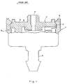
- a known irrigation emitter unit comprises an outer cylindrical member 1 and an inner member 2 having a substantially planar upper surface 3 and through which extends a central outlet port 4.
- the outer member 1 on the other hand, is provided with a coupling nipple 5 by which the emitter unit can be coupled to an irrigation pipe (not shown).
- the outer and inner members are formed of like plastics materials.
- peripheral groove 6 constituting an undercut, and having upper and lower sloping edges.
- the inner member 2 is formed with a peripheral flanged rib 7 which has correspondingly sloping edges. As seen in Fig. 1, when the emitter unit is assembled and the inner member is forced into position as shown, the flanged rib 7 is located within the peripheral groove 6 and is retained therein.
- the shape and mode of location of the flanged rib 7 within the recess 6 are such that the effective retention of the inner member 2 within the outer member 1 cannot always be ensured, especially when a relatively high pressure develops within the emitter unit, in which case the inner member 2 can well be expelled from the outer member 1.
- the formation of the undercut recess 6 with sloping edges is essentially dictated by standard plastic molding technology and the presence of these sloping edges renders the retention of the inner member 2 within the outer member 1 even more difficult.
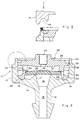
- Fig. 2 of the drawings shows the respective components of an irrigation emitter unit assembled together prior to the final operation designed to ensure the effective sealing retention of the components one within the other.
- the unit comprises an outer member 11 consisting of a substantially cylindrical casing portion 12, a coupling nipple portion 13, the portions 12 and 13 being integrally coupled together via a sloping portion 14.
- the coupling nipple 13 defines a central inlet port 15 which communicates with a central portion of an inlet control chamber 16 formed in the outer member 11.
- the sloping portion 14 is formed integrally with an annular support 17 within which is defined the inlet control chamber 16, the annular support 17 tapering towards a circular apex 18.
- An annular groove 19 is formed in an upper surface of the tapering portion 14 adjacent the inner surface of the cylindrical portion 12.
- the cylindrical portion 12 is formed integrally with an upwardly projecting terminal portion 20 which is of reduced thickness as compared with the remainder of the cylindrical portion 12.
- An inner member 25 comprises an upper, substantially planar annular portion 26 having a central outlet port 27 and being formed with a downwardly depending skirt portion 28, the latter terminating in a bevelled end portion 29 which fits within the annular groove 19.
- the upper portion 26 is formed with an outer peripheral flange 30 having an outer annular surface which fits sealingly against the inner annular surface of the cylindrical portion 12.
- the bevelled end portion 29 is formed with an outer annular surface which fits sealingly against the inner surface of the cylindrical portion 12.
- a flow reducing path 33 Defined between the outer surface of the skirt portion 28 and the inner surface of the cylindrical portion 12 is a flow reducing path 33.
- One end of the flow reducing path 33 communicates with an annular region 34 defined between an inner surface of the skirt portion 28 and an outer surface of the support 17.
- An opposite end of the flow reducing path 33 communicates with an upper region defined within the inner member 25.
- An inwardly directed annular shoulder 35 having an innermost corner 36 is formed on the inner surface of the skirt portion 28.
- a circular flexible membrane 37 is centrally supported at its under surface on the circular tip 18 of the support 17 and, at its outer surface against the circular corner 36 of the shoulder 35.
- the membrane is so supported as to be slightly flexed upwardly.
- the membrane 37 defines, together with the support 17, an inlet control chamber 16 and, with the under surface of the planar portion 26, an outlet control chamber 38.
- an ultrasonic distortion is carried out whereby, as shown in Fig. 3 of the drawings, an ultrasonic tip 41, having a suitably shaped annular spherical recess 42, is brought into contact with the upper end portions of the assembled unit and the process of staking results in the melting and reforming of the terminal portion 20 (the melted and re-formed portions being shown in Fig. 3 in hatched lines).
- an ultrasonic tip 41 having a suitably shaped annular spherical recess 42, is brought into contact with the upper end portions of the assembled unit and the process of staking results in the melting and reforming of the terminal portion 20 (the melted and re-formed portions being shown in Fig. 3 in hatched lines).
- the terminal portion 20 has been converted into an inwardly directed peripheral flanged end portion 45 which bears against the terminal peripheral rin 30 and is, in fact, welded to this rib, thereby effectively and sealing retaining the inner portion 26 within the outer portion 11.
- the emitter unit construction just described has the following distinct advantages:
Landscapes
- Engineering & Computer Science (AREA)
- Mechanical Engineering (AREA)
- Life Sciences & Earth Sciences (AREA)
- Soil Sciences (AREA)
- Water Supply & Treatment (AREA)
- Environmental Sciences (AREA)
- Vehicle Body Suspensions (AREA)
- Infusion, Injection, And Reservoir Apparatuses (AREA)
- Paper (AREA)
- Rigid Pipes And Flexible Pipes (AREA)
- Surgical Instruments (AREA)
- Fluid-Pressure Circuits (AREA)
- External Artificial Organs (AREA)
- Nozzles (AREA)
- Reciprocating Pumps (AREA)
Claims (14)
- Bewässerungssprüheinheit, in Kombination umfassend ein äußeres Bauteil (11) von im wesentlichen zylindrischer Form mit einem Basisabschnitt (14), der integral mit einer Flüssigkeitsströmungskopplungseinrichtung (13) verbunden ist, wobei ein Flüssigkeitsströmungseinlaß (15) in dem Basisabschnitt ausgebildet ist; ein inneres Bauteil (25), das in dem äußeren Bauteil eingepaßt ist; eine längliche Nut (33), die in einer zylindrischen Oberfläche des inneren Bauteils ausgebildet ist und mit einer angrenzenden Oberfläche des äußeren Bauteils einen Strömungsbegrenzungs-Strömungsdurchtritt festlegt:
dadurch gekennzeichnet,
daß das äußere Bauteil (11) einen abgeschrägten Basisabschnitt (14) aufweist, der integral mit der Flüssigkeitsströmungsanschlußeinrichtung (13) ausgebildet ist;
daß ein nach innen gerichteter Umfangsflanschrandabschnitt (45) des äußeren Bauteils (11) im wesentlichen unter 90° bezüglich der zylindrischen Wände (12) des äußeren Bauteils (11) verläuft;
daß das innere Bauteil (25) einen Gehäuseabschnitt (28, 29) von im wesentlichen zylindrischer Form aufweist, der im wesentlichen abdichtend in dem äußeren Bauteil (11) eingepaßt ist, wobei ein Basisabschnitt (24) hiervon gegen eine innere Oberfläche (19) des Basisabschnitts (14) anstößt, und einen Deckelabschnitt (26) aufweist, der integral hiermit ausgebildet ist;
daß das innere und das äußere Bauteil (25, 11) aus gleichen oder ähnlichen Kunststoffmaterialien ausgebildet sind;
daß der nach innen gerichtete Umfangsflanschrandabschnitt (25) des äußeren Bauteils eine untere Oberfläche aufweist; wobei ein Umfangsrandabschnitt (30) des Deckelabschnitts (26) unterhalb des Flanschrandabschnitts (25) des äußeren Bauteils neben diesem angeordnet ist;
wobei die obere Oberfläche des Umfangsrandabschnitts (30) des Deckelabschnitts (26) dichtend an der unteren Oberfläche des Randabschnitts (45) des äußeren Bauteils verschweißt ist;
daß die längliche Nut (33) in der zylindrischen Oberfläche des Gehäuseabschnitts (28) ausgebildet ist und mit der angrenzenden Oberfläche des äußeren Bauteils (12) einen Strömungsbegrenzungs-Strömungsdurchtritt (33) festlegt;
daß ein Hohlraum (38) in dem Gehäuseabschnitt (28, 29) ausgebildet ist und in Verbindung steht mit seinem einen Ende mit dem Flüssigkeitsströmungseinlaß (15) und mit seinem gegenüberliegenden Ende mit einem Flüssigkeitsströmungsauslaß (27), der in dem Deckelabschnitt (26) ausgebildet ist;
daß ein nach innen gerichteter Flansch (35) integral mit den Wänden des Hohlraums (38) an einer mittleren Stelle längs deren axialer Ausdehnung ausgebildet ist und einen Rand (36) aufweist, der eine Öffnung festlegt, die eine wesentlich größere Fläche aufweist als die Fläche des Flüssigkeitsströmungsauslasses (27), wobei der Rand (36) von dem Flüssigkeitsströmungsauslaß (27) beabstandet ist;
daß eine elastisch flexible Membrane (37) innerhalb der Einheit angeordnet ist und gegen den Rand (36) gehalten werden kann, um so die Öffnung zu schließen und um so mit den Wänden des Hohlraums eine Einlaßsteuerkammer (16), die in Verbindung steht mit dem Flüssigkeitseinlaß (15) und einem Ende des Strömungsbegrenzungs-Strömungsdurchtritts (33), sowie eine Auslaßsteuerkammer (38), die mit dem Flüssigkeitsauslaß (27) und einem gegenüberliegendem Ende des Strömungsbegrenzungs-Strömungsdurchtritts (33) in Verbindung steht, festzulegen;
wobei die Anordung so ist, daß, wenn der Flüssigkeitsdruck in der Einlaßsteuerkammer (16) den Flüssigkeitsdruck in der Auslaßsteuerkammer (38) um ein vorbestimmtes Maß übersteigt, sich die Membrane (37) elastisch zu der Auslaßöffnung (27) hin durchbiegt, um so mit einem Rand der Auslaßöffnung (27) einen begrenzten Ausflußdurchtritt festzulegen, wodurch Änderungen der Ausflußrate begrenzt werden. - Bewässerungssprüheinheit nach Anspruch 1, dadurch gekennzeichnet, daß in dem äußeren Bauteil (11) ein abgeschrägter ringförmiger Membranauflageabschnitt (17) ausgebildet ist mit einer ringförmigen Abschlußspitze (18), die gegen eine untere Oberfläche der Membrane (37) trägt, wodurch, und vor der Ausübung eines minimalen Flüssigkeitsdruckes auf diese untere Oberfläche, die letztere dichtend gegen die Spitze (18) trägt und eine obere Oberfläche hiervon dichtend gegen den Rand (36) des Flansches (35) trägt.
- Verfahren zum Herstellen einer Flüssigkeitsströmungssteuereinheit mit einem inneren Bauteil, daß haltend in einem im wesentlichen zylindrischen äußeren Bauteil eingepaßt ist, wobei die Bauteile aus gleichen oder ähnlichen Kunststoffmaterialien gebildet sind, gekennzeichnet durch die Schritte:
Einfügen des inneren Bauteils (25) in das äußere Bauteil (11), wobei ein erster Umfangsrandabschnitt (20) des äußeren Bauteils (11) über einen zweiten und angrenzenden Umfangsrandabschnitt (30) des inneren Bauteils (25) hinausragt;
winkliges Verschieben des ersten Umfangsrandabschnitts um im wesentlichen zwischen 70°-110° bezüglich der zylindrischen Wände des äußeren Bauteils und in Nebeneinanderlage mit dem zweiten Umfangsrandabschnitt und Verschweißen einer unteren Oberfläche des ersten Umfangsrandabschnitts mit einer oberen Oberfläche des zweiten Umfangsrandabschnitts;
wobei das Verschieben und Schweißen mittels Ultraschallschwingungen bewirkt wird, die auf den ersten Umfangsrandabschnitt aufgebracht werden. - Flüssigkeitssteuereinheit, hergestellt gemäß dem Verfahren nach Anspruch 3 und umfassend:
ein äußeres, im wesentlichen zylindrisches Bauteil (11), daß aus einem Kunststoffmaterial gebildet ist;
einen nach innen gerichteten Umfangsflanschrandabschnitt (45) des äußeren Bauteils (11);
ein inneres Bauteil (25), das aus einem gleichen oder ähnlichen Kunststoffmaterial gebildet ist und innerhalb des äußeren Bauteils (11) eingepaßt ist;
einen Umfangsrandabschnitt (30) des inneren Bauteils (25), das unter dem Flanschrandabschnitt (45) des äußeren Bauteils (11) neben diesem angeordnet ist, wobei eine untere Oberfläche des Flanschrandabschnitts mit einer oberen Oberfläche des Umfangsrandabschnitts verschweißt ist, wodurch das innere Bauteil (25) in dem äußeren Bauteil (11) gehalten wird;
einen Flüssigkeitsströmungssteuerdurchtritt (33), der in der Einheit ausgebildet ist und festgelegt ist zwischen aneinandergrenzenden Flächen des äußeren und des inneren Bauteils (11, 25);
einen Flüssigkeitsströmungseinlaß (15), der in einem der Bauteile ausgebildet ist und mit einem Ende des Flüssigkeitsströmungssteuerdurchtritts (33) in Verbindung steht; und
einen Flüssigkeitsströmungsauslaß (27), der in dem anderen der Bauteile ausgebildet ist und mit einem gegenüberliegenden Ende des Flüssigkeitsströmungssteuerdurchtritts (33) verbunden ist. - Flüssigkeitströmungssteuereinheit nach Anspruch 4, dadurch gekennzeichnet, daß das innere Bauteil (25) mit einer oberen Oberfläche (26) ausgebildet ist, die ebenfalls eine obere äußere Oberfläche (26) der Einheit darstellt, wobei der Umfangsrandabschnitt (45) des äußeren Bauteils (11) im wesentlichen auf einer Höhe mit der oberen äußeren Oberfläche (26) angeordnet ist.
- Flüssigkeitsströmungssteuereinheit nach Anspruch 4, dadurch gekennzeichnet, daß die äußere Oberfläche des inneren Bauteils (25) im wesentlichen eben ist, daß der Umfangsrandabschnitt (30) bezüglich der ebenen äußeren Oberfläche (26) zurückgenommen ist und der Umfangsrandabschnitt (45) des äußeren Bauteils (11) im wesentlichen in dem zurückgenommenen Randabschnitt (30) angeordnet ist.
- Flüssigkeitssteuereinheit nach einem der Ansprüche 4, 5 oder 6, dadurch gekennzeichnet, daß das äußere Bauteil (11) eine im wesentliche zylindrische Form aufweist und der Umfangsrandabschnitt (45) hiervon unter einem Winkel von zwischen 70°-110° bezüglich der zylindrischen Wand (12) hiervon ausgerichtet ist.
- Flüssigkeitsströmungssteuereinheit nach Anspruch 7, wobei der Winkel im wesentlichen gleich 90°.
- Flüssigkeitsströmungssteuereinheit nach Anspruch 7 oder 8, dadurch gekennzeichnet, daß das innere Bauteil (25) einen Gehäuseabschnitt (28) von im wesentlichen zylindrischer Form aufweist sowie einen hiermit integral ausgebildeten Deckelabschnitt (26), wobei eine äußere Fläche hiervon die äußere Oberfläche darstellt.
- Flüssigkeitsströmungssteuereinheit nach Anspruch 9, dadurch gekennzeichnet, daß der Flüssigkeitsströmungssteuerdurchtritt (33) festgelegt wird von einer länglichen Nut (33), die in einer ringförmigen Fläche von einem der Bauteile (25, 11) und der angrenzenden Oberfläche des anderen Bauteils festgelegt wird.
- Flüssigkeitsströmungssteuereinheit nach Anspruch 10, dadurch gekennzeichnet, daß die Nut (33) in der äußeren zylindrischen Oberfläche (28) des inneren Bauteils (25) ausgebildet ist.
- Flüssigkeitsströmungssteuereinheit nach einem der Ansprüche 9, 10 oder 11, dadurch gekennzeichnet, daß in der Einheit ein zentraler Hohlraum festgelegt ist, der von einem Rand (36) umgeben ist, wobei der Rand (36) eine Fläche festlegt, die wesentlich größer ist als diejenige des Flüssigkeitsströmungsauslasses (27) und von dem Flüssigkeitsströmungsauslaß (27) beabstandet ist; daß die Vorrichtung desweiteren eine flexible Membrane (37) aufweist, die darin angeordnet ist und gegen den Rand (36) trägt und hierdurch mit den Wänden des Hohlraums (38) eine Flüssigkeitseinlaßsteuerkammer (16) festlegt, die mit dem Flüssigkeitseinlaß (15) in Verbindung steht, sowie eine Flüssigkeitsauslaßsteuerkammer (38), die mit dem Flüssigkeitsauslaß (27) in Verbindung steht, wobei die Anordung so ist, daß, wenn der Flüssigkeitsdruck in der Einlaßkammer (16) den Flüssigkeitsdruck in der Auslaßkammer (38) um ein vorbestimmtes Maß übersteigt, die Membrane (37) sich elastisch zur Auslaßöffnung (27) hin durchbiegt, um so mit einem Rand der Auslaßöffnung (27) einen begrenzten Ausflußdurchtritt festzulegen, um somit die Änderung der Ausflußrate von Flüssigkeit von dem Flüssigkeitsauslaß (27) zu begrenzen.
- Flüssigkeitsströmungssteuereinheit nach Anspruch 12, dadurch gekennzeichnet, daß der Gehäuseabschnitt (28) an einer Basis (29) hiervon an einer inneren Oberfläche (19) des äußeren Bauteils (11) anliegt.
- Flüssigkeitsströmungssteuereinheit nach einem der Ansprüche 4 bis 13, dadurch gekennzeichnet, daß das äußere Bauteil (11) mit einer Flüssigkeitsströmungsanschlußeinrichtung (13) ausgebildet ist, die sich von einem Basisabschnitt (14) hiervon erstreckt und mit dem Flüssigkeitsströmungseinlaß (15) in Verbindung steht, der in dem Basisabschnitt (14) ausgebildet ist, wobei der Basisabschnitt (14) einen im wesentlichen abgeschrägten Aufbau hat.
Applications Claiming Priority (2)
| Application Number | Priority Date | Filing Date | Title |
|---|---|---|---|
| IL96106A IL96106A (en) | 1990-10-25 | 1990-10-25 | Fluid flow control unit for example for an irrigation emitter |
| IL96106 | 1990-10-25 |
Publications (2)
| Publication Number | Publication Date |
|---|---|
| EP0482843A1 EP0482843A1 (de) | 1992-04-29 |
| EP0482843B1 true EP0482843B1 (de) | 1995-12-13 |
Family
ID=11061703
Family Applications (1)
| Application Number | Title | Priority Date | Filing Date |
|---|---|---|---|
| EP91309662A Expired - Lifetime EP0482843B1 (de) | 1990-10-25 | 1991-10-18 | Verbesserte Flüssigkeitssteuereinheit |
Country Status (11)
| Country | Link |
|---|---|
| US (1) | US5279462A (de) |
| EP (1) | EP0482843B1 (de) |
| AT (1) | ATE131346T1 (de) |
| AU (1) | AU639374B2 (de) |
| BR (1) | BR9104607A (de) |
| DE (1) | DE69115437T2 (de) |
| DK (1) | DK0482843T3 (de) |
| ES (1) | ES2080914T3 (de) |
| GR (1) | GR3019233T3 (de) |
| IL (1) | IL96106A (de) |
| ZA (1) | ZA918378B (de) |
Families Citing this family (69)
| Publication number | Priority date | Publication date | Assignee | Title |
|---|---|---|---|---|
| US5820028A (en) * | 1992-02-26 | 1998-10-13 | Naan Irrigation Systems | Irrigation apparatus |
| IL109486A0 (en) * | 1994-04-29 | 1994-07-31 | Naan Irrigation Systems | Irrigation apparatus |
| IL106572A0 (en) * | 1992-11-19 | 1993-12-08 | Paskal Avizarey Kshira Ltd | Outlet connector for irrigation pipe |
| US5634594A (en) * | 1993-07-30 | 1997-06-03 | Cohen; Amir | Flow control device particularly useful in drip irrigation emitters |
| US5636797A (en) * | 1993-07-30 | 1997-06-10 | Cohen; Amir | Drip irrigation emitter and flow control unit included therein |
| US5413282A (en) * | 1993-10-28 | 1995-05-09 | James Hardie Irrigation, Inc. | Pressure compensating emitter with shut down flush |
| US6085986A (en) * | 1994-05-03 | 2000-07-11 | Yu; Michael | Oscillating disk drives |
| US5711482A (en) * | 1994-05-03 | 1998-01-27 | Yu; Michael | Resilient disk drip irrigation devices |
| US6305617B1 (en) | 1994-05-03 | 2001-10-23 | Michael Yu | Oscillating disk dental hygiene device |
| US5615838A (en) * | 1995-03-10 | 1997-04-01 | Drip Irrigation Systems, Ltd. | In-line retention drip emitter |
| IL122777A (en) * | 1997-12-28 | 2003-12-10 | Amir Cohen | Valve controlled drip irrigation lines |
| IL131716A (en) | 1998-12-21 | 2006-09-05 | Amir Cohen | Drip irrigation emitters |
| IL129817A (en) * | 1999-05-06 | 2002-12-01 | Plassim Tech Plastics Works | Method for producing an irrigation pipeline with inner emitters |
| IL134695A0 (en) * | 2000-02-23 | 2001-07-24 | Naan Irrigation Systems C S Lt | Flow regulators with flexibile diaphragms |
| FR2805699A1 (fr) | 2000-02-25 | 2001-08-31 | Thomson Multimedia Sa | Methode de gestion d'une liste d'evenements diffuses et dispositif associe |
| GR20000100065A (el) | 2000-02-28 | 2001-10-31 | Σταλακτης με φιλτρο εισοδου του νερου και μεθοδος συναρμολογησης | |
| RU2181539C2 (ru) * | 2000-05-17 | 2002-04-27 | Поволжский научно-исследовательский институт эколого-мелиоративных технологий | Капельница |
| RU2281646C1 (ru) * | 2005-02-24 | 2006-08-20 | Государственное научное учреждение Поволжский научно-исследовательский институт эколого-мелиоративных технологий Российской академии сельскохозяйственных наук | Устройство для систем капельного орошения |
| RU2282344C1 (ru) * | 2005-03-17 | 2006-08-27 | Государственное научное учреждение Поволжский научно-исследовательский институт эколого-мелиоративных технологий Российской академии сельскохозяйственных наук | Капельный водовыпуск |
| RU2282347C1 (ru) * | 2005-03-28 | 2006-08-27 | Государственное научное учреждение Прикаспийский научно-исследовательский институт аридного земледелия Российской академии сельскохозяйственных наук | Капельный водовыпуск |
| RU2282348C1 (ru) * | 2005-03-28 | 2006-08-27 | Государственное научное учреждение Прикаспийский научно-исследовательский институт аридного земледелия Российской академии сельскохозяйственных наук | Водовыпуск для капельного орошения |
| RU2282346C1 (ru) * | 2005-03-28 | 2006-08-27 | Государственное научное учреждение Прикаспийский научно-исследовательский институт аридного земледелия Российской академии сельскохозяйственных наук | Капельный водовыпуск для систем капельного орошения |
| US8302887B2 (en) * | 2005-03-31 | 2012-11-06 | Rain Bird Corporation | Drip emitter |
| RU2294624C1 (ru) * | 2005-07-28 | 2007-03-10 | Государственное научное учреждение Поволжский научно-исследовательский институт эколого-мелиоративных технологий Российской академии сельскохозяйственных наук | Система капельного полива |
| RU2294626C1 (ru) * | 2005-08-10 | 2007-03-10 | Государственное научное учреждение Поволжский научно-исследовательский институт эколого-мелиоративных технологий Российской академии сельскохозяйственных наук | Система капельного полива растений |
| CN101557701A (zh) * | 2005-08-17 | 2009-10-14 | 内塔芬有限公司 | 灌溉发射器内的泡沫硅树脂部件 |
| IL171482A (en) | 2005-10-19 | 2014-12-31 | Zvi Einav | Drip emitter with an independent non-drain valve |
| CN101371207B (zh) * | 2005-12-27 | 2010-08-25 | 内塔芬有限公司 | 流体流量控制调节器 |
| US7648085B2 (en) * | 2006-02-22 | 2010-01-19 | Rain Bird Corporation | Drip emitter |
| RU2311020C1 (ru) * | 2006-05-26 | 2007-11-27 | Федеральное государственное образовательное учреждение высшего профессионального образования "Волгоградская государственная сельскохозяйственная академия" | Водовыпуск поливного трубопровода |
| ITSV20060018A1 (it) * | 2006-07-10 | 2008-01-11 | Irritec S R L | Emettitore regolabile per fluidi in particolare negli impianti di irrigazione |
| EP1884157A1 (de) * | 2006-08-03 | 2008-02-06 | GARDENA Manufacturing GmbH | Bewässerungsvorrichtung |
| RU2330404C1 (ru) * | 2007-01-19 | 2008-08-10 | Государственное научное учреждение Поволжский научно-исследовательский институт эколого-мелиоративных технологий Российской академии сельскохозяйственных наук | Водовыпуск гибкого поливного трубопровода |
| RU2335890C1 (ru) * | 2007-03-14 | 2008-10-20 | Государственное научное учреждение Поволжский научно-исследовательский институт эколого-мелиоративных технологий Российской академии сельскохозяйственных наук | Водовыпуск гибкого поливного трубопровода |
| RU2337527C1 (ru) * | 2007-05-02 | 2008-11-10 | Государственное научное учреждение Поволжский научно-исследовательский институт эколого-мелиоративных технологий Российской академии сельскохозяйственных наук | Водовыпуск поливного трубопровода |
| RU2373697C1 (ru) * | 2008-08-05 | 2009-11-27 | Федеральное государственное образовательное учреждение высшего профессионального образования Волгоградская государственная сельскохозяйственная академия | Саморегулирующийся водовыпуск поливного трубопровода |
| US8628032B2 (en) | 2008-12-31 | 2014-01-14 | Rain Bird Corporation | Low flow irrigation emitter |
| IL204685A (en) * | 2009-03-23 | 2014-07-31 | Rosenberg Avner | A device for flow control especially useful for drip irrigation drips |
| US8317111B2 (en) | 2010-01-31 | 2012-11-27 | Amirim Products Development & Patents Ltd. | Bi-component drip emitter |
| GB2484924A (en) | 2010-10-25 | 2012-05-02 | Amirim Products Dev & Patents Ltd | An on line drip irrigation emitter having an inlet filtering dvice |
| US20130248622A1 (en) | 2012-03-26 | 2013-09-26 | Jae Yung Kim | Drip line and emitter and methods relating to same |
| US9485923B2 (en) | 2012-03-26 | 2016-11-08 | Rain Bird Corporation | Elastomeric emitter and methods relating to same |
| US9877440B2 (en) | 2012-03-26 | 2018-01-30 | Rain Bird Corporation | Elastomeric emitter and methods relating to same |
| US10440903B2 (en) | 2012-03-26 | 2019-10-15 | Rain Bird Corporation | Drip line emitter and methods relating to same |
| CN103062466B (zh) * | 2013-01-11 | 2014-11-05 | 李光永 | 一种微灌毛管进口流量调节器 |
| US9872444B2 (en) | 2013-03-15 | 2018-01-23 | Rain Bird Corporation | Drip emitter |
| US9949448B2 (en) * | 2015-01-14 | 2018-04-24 | Amirim Products Development & Patents Ltd. | Modular in line button drip emitter system |
| US10869434B2 (en) | 2013-07-09 | 2020-12-22 | Amirim Products Development & Patents Ltd. | Elliptical in line button dripper with extended bonding zones |
| US9462760B2 (en) | 2013-07-09 | 2016-10-11 | Amirim Products Development & Patents Ltd. | In line button drip emitter |
| US10631473B2 (en) | 2013-08-12 | 2020-04-28 | Rain Bird Corporation | Elastomeric emitter and methods relating to same |
| US10285342B2 (en) | 2013-08-12 | 2019-05-14 | Rain Bird Corporation | Elastomeric emitter and methods relating to same |
| USD811179S1 (en) | 2013-08-12 | 2018-02-27 | Rain Bird Corporation | Emitter part |
| US10172302B2 (en) * | 2013-09-25 | 2019-01-08 | Netafim, Ltd. | Drip emitter |
| US9883640B2 (en) | 2013-10-22 | 2018-02-06 | Rain Bird Corporation | Methods and apparatus for transporting elastomeric emitters and/or manufacturing drip lines |
| WO2015070915A1 (de) | 2013-11-14 | 2015-05-21 | Alfred Kärcher Gmbh & Co. Kg | Sprühdüsenvorrichtung und verfahren zur einstellung eines oder mehrerer sprühstrahlen |
| EP3157681A1 (de) * | 2014-06-20 | 2017-04-26 | Medspray B.V. | Aerosol- oder sprühvorrichtung, sprühdüseneinheit und verfahren zur herstellung davon |
| US10330559B2 (en) | 2014-09-11 | 2019-06-25 | Rain Bird Corporation | Methods and apparatus for checking emitter bonds in an irrigation drip line |
| RU2579468C1 (ru) * | 2014-12-24 | 2016-04-10 | Михаил Иванович Голубенко | Водовыпуск поливного трубопровода |
| PT3383167T (pt) | 2015-12-03 | 2021-01-05 | Netafim Ltd | Emissor de gotas |
| JP6689634B2 (ja) * | 2016-03-17 | 2020-04-28 | 株式会社エンプラス | エミッタおよび点滴灌漑用チューブ |
| CN107258475A (zh) | 2016-04-07 | 2017-10-20 | 阿米尔·科恩 | 内嵌式按钮滴灌灌水器 |
| US10375904B2 (en) | 2016-07-18 | 2019-08-13 | Rain Bird Corporation | Emitter locating system and related methods |
| US10100863B2 (en) * | 2016-07-27 | 2018-10-16 | GM Global Technology Operations LLC | External heat-stake arrangement |
| US11051466B2 (en) | 2017-01-27 | 2021-07-06 | Rain Bird Corporation | Pressure compensation members, emitters, drip line and methods relating to same |
| US10626998B2 (en) * | 2017-05-15 | 2020-04-21 | Rain Bird Corporation | Drip emitter with check valve |
| USD883048S1 (en) | 2017-12-12 | 2020-05-05 | Rain Bird Corporation | Emitter part |
| US11985924B2 (en) | 2018-06-11 | 2024-05-21 | Rain Bird Corporation | Emitter outlet, emitter, drip line and methods relating to same |
| CN113226559B (zh) * | 2019-01-03 | 2023-07-25 | 阿普塔尔拉多尔夫策尔有限责任公司 | 喷嘴单元、具有这种喷嘴单元的液体分配器和用于制造这种喷嘴单元的方法 |
| US12207599B2 (en) | 2021-10-12 | 2025-01-28 | Rain Bird Corporation | Emitter coupler and irrigation system |
Family Cites Families (15)
| Publication number | Priority date | Publication date | Assignee | Title |
|---|---|---|---|---|
| FR48310E (fr) * | 1936-07-31 | 1937-12-27 | Accessoire Precision | Perfectionnements apportés aux dispositifs de commande à distance, notamment à ceux pour véhicules automobiles |
| FR48811E (fr) * | 1937-02-19 | 1938-07-12 | Tube à vide amplificateur | |
| US2431238A (en) * | 1946-04-15 | 1947-11-18 | Friedman Theodore | Process of locking flat members to bodies |
| US3436803A (en) * | 1966-02-07 | 1969-04-08 | Stanley J Sarnoff | Uniting parts by the use of vibrational and positive material deforming forces and article made thereby |
| US3970273A (en) * | 1975-01-10 | 1976-07-20 | Arundale, Inc. | Appliance foot with secure resilient pad |
| US3998427A (en) * | 1975-12-11 | 1976-12-21 | Clarence Bentley | Self-cleaning drip irrigation valve |
| US4084749A (en) * | 1976-04-11 | 1978-04-18 | Mordeki Drori | Flow reducing devices particularly useful as drip emitters for drip irrigation |
| IL50650A (en) * | 1976-10-10 | 1979-05-31 | Drori Mordeki | Regulated flow-reducing device particularly useful for drip irrigation |
| IL50766A (en) * | 1976-10-26 | 1983-06-15 | Hydro Plan Eng Ltd | Irrigation emitter unit |
| DE2729458C3 (de) * | 1977-06-30 | 1981-07-16 | Arcu Armaturindustri AB, Alstermo | Strömungsregulator, insbesondere zum Einbau zwischen einem Wasserkran und einem Wasserleitungsende |
| IL58176A0 (en) * | 1979-09-04 | 1979-12-30 | Bron Dan | A self-regulating nozzle for a liquid supply line |
| FR2468810A1 (fr) * | 1979-10-29 | 1981-05-08 | Irrifrance Sa | Limiteur de debit |
| IL58773A (en) * | 1979-11-22 | 1982-12-31 | Hydro Plan Eng Ltd | Emitter unit |
| SU935011A1 (ru) * | 1981-01-19 | 1982-06-15 | Всесоюзное Научно-Производственное Объединение По Механизации Орошения "Радуга" | Водовыпуск дл капельного орошени |
| CA1292846C (en) * | 1988-09-20 | 1991-12-10 | Pierre P. Meunier | Charcoal bed assembly |
-
1990
- 1990-10-25 IL IL96106A patent/IL96106A/en not_active IP Right Cessation
-
1991
- 1991-10-17 US US07/778,565 patent/US5279462A/en not_active Expired - Lifetime
- 1991-10-18 AU AU86003/91A patent/AU639374B2/en not_active Expired
- 1991-10-18 AT AT91309662T patent/ATE131346T1/de not_active IP Right Cessation
- 1991-10-18 ES ES91309662T patent/ES2080914T3/es not_active Expired - Lifetime
- 1991-10-18 EP EP91309662A patent/EP0482843B1/de not_active Expired - Lifetime
- 1991-10-18 DE DE69115437T patent/DE69115437T2/de not_active Expired - Lifetime
- 1991-10-18 DK DK91309662.4T patent/DK0482843T3/da active
- 1991-10-21 ZA ZA918378A patent/ZA918378B/xx unknown
- 1991-10-24 BR BR919104607A patent/BR9104607A/pt not_active IP Right Cessation
-
1996
- 1996-03-06 GR GR960400641T patent/GR3019233T3/el unknown
Also Published As
| Publication number | Publication date |
|---|---|
| IL96106A0 (en) | 1991-07-18 |
| ZA918378B (en) | 1992-07-29 |
| DK0482843T3 (da) | 1996-03-04 |
| EP0482843A1 (de) | 1992-04-29 |
| AU8600391A (en) | 1992-04-30 |
| AU639374B2 (en) | 1993-07-22 |
| ES2080914T3 (es) | 1996-02-16 |
| DE69115437D1 (de) | 1996-01-25 |
| DE69115437T2 (de) | 1996-05-02 |
| BR9104607A (pt) | 1992-06-09 |
| GR3019233T3 (en) | 1996-06-30 |
| US5279462A (en) | 1994-01-18 |
| ATE131346T1 (de) | 1995-12-15 |
| IL96106A (en) | 1998-04-05 |
Similar Documents
| Publication | Publication Date | Title |
|---|---|---|
| EP0482843B1 (de) | Verbesserte Flüssigkeitssteuereinheit | |
| EP0191969B1 (de) | Ventilvorrichtung | |
| US4366926A (en) | Irrigation emitter unit | |
| US4281798A (en) | Drip or trickle emitter | |
| CA1052835A (en) | Bonded tfe seal with dual lip | |
| US7243863B2 (en) | Shower head | |
| JP3266356B2 (ja) | 逆止弁 | |
| US4356823A (en) | Suction control | |
| US4624286A (en) | Degasifying valve for containers | |
| US20170290277A1 (en) | In line button drip emitter | |
| JP4210032B2 (ja) | エーロゾル傾斜弁及び取付けカップとエーロゾル傾斜弁弁棒の形成方法 | |
| CA1271105A (en) | Valve for relieving pressure or checking reverse flow | |
| KR100277107B1 (ko) | 개량된 밀봉 장치와 그 형성방법 | |
| US3515316A (en) | Actuator for aerosol valves | |
| EP1373768B1 (de) | Absperrschieber | |
| US5681152A (en) | Membrane type fluid pump | |
| US5396922A (en) | Ball valve | |
| CN102066208A (zh) | 具有整体密封件的连接器 | |
| EP0188300B1 (de) | Verfahren zum Herstellen eines Dichtungskörpers, insbesondere für eine Rohrverbindung, und ein durch dieses Verfahren hergestellter Dichtungskörper | |
| GB2123094A (en) | Flexible-bag self-closing metering dispensing valve | |
| US6481600B2 (en) | Dropper assembly | |
| US5104090A (en) | Irrigation valve | |
| CA2469942A1 (en) | Two-part closure system and nozzle with groove | |
| EP0467500B1 (de) | Ventil zum Füllen von Behältern bis zu einem vorbestimmten Niveau | |
| JPS5924303B2 (ja) | 2個部片よりなる過圧逃し弁 |
Legal Events
| Date | Code | Title | Description |
|---|---|---|---|
| PUAI | Public reference made under article 153(3) epc to a published international application that has entered the european phase |
Free format text: ORIGINAL CODE: 0009012 |
|
| AK | Designated contracting states |
Kind code of ref document: A1 Designated state(s): AT BE CH DE DK ES FR GB GR IT LI LU NL SE |
|
| 17P | Request for examination filed |
Effective date: 19921012 |
|
| 17Q | First examination report despatched |
Effective date: 19931111 |
|
| GRAA | (expected) grant |
Free format text: ORIGINAL CODE: 0009210 |
|
| AK | Designated contracting states |
Kind code of ref document: B1 Designated state(s): AT BE CH DE DK ES FR GB GR IT LI LU NL SE |
|
| REF | Corresponds to: |
Ref document number: 131346 Country of ref document: AT Date of ref document: 19951215 Kind code of ref document: T |
|
| ITF | It: translation for a ep patent filed | ||
| REF | Corresponds to: |
Ref document number: 69115437 Country of ref document: DE Date of ref document: 19960125 |
|
| REG | Reference to a national code |
Ref country code: CH Ref legal event code: NV Representative=s name: A. BRAUN, BRAUN, HERITIER, ESCHMANN AG PATENTANWAE |
|
| REG | Reference to a national code |
Ref country code: ES Ref legal event code: FG2A Ref document number: 2080914 Country of ref document: ES Kind code of ref document: T3 |
|
| REG | Reference to a national code |
Ref country code: DK Ref legal event code: T3 |
|
| ET | Fr: translation filed | ||
| REG | Reference to a national code |
Ref country code: GR Ref legal event code: FG4A Free format text: 3019233 |
|
| PG25 | Lapsed in a contracting state [announced via postgrant information from national office to epo] |
Ref country code: AT Effective date: 19961018 |
|
| PLBE | No opposition filed within time limit |
Free format text: ORIGINAL CODE: 0009261 |
|
| STAA | Information on the status of an ep patent application or granted ep patent |
Free format text: STATUS: NO OPPOSITION FILED WITHIN TIME LIMIT |
|
| PG25 | Lapsed in a contracting state [announced via postgrant information from national office to epo] |
Ref country code: SE Effective date: 19961019 |
|
| PG25 | Lapsed in a contracting state [announced via postgrant information from national office to epo] |
Ref country code: CH Effective date: 19961031 Ref country code: BE Effective date: 19961031 Ref country code: LU Free format text: LAPSE BECAUSE OF NON-PAYMENT OF DUE FEES Effective date: 19961031 Ref country code: LI Effective date: 19961031 |
|
| 26N | No opposition filed | ||
| BERE | Be: lapsed |
Owner name: HYDROPLAN ENGINEERING LTD Effective date: 19961031 |
|
| REG | Reference to a national code |
Ref country code: CH Ref legal event code: PL |
|
| EUG | Se: european patent has lapsed |
Ref document number: 91309662.4 |
|
| REG | Reference to a national code |
Ref country code: GB Ref legal event code: IF02 |
|
| PGFP | Annual fee paid to national office [announced via postgrant information from national office to epo] |
Ref country code: DK Payment date: 20101028 Year of fee payment: 20 Ref country code: FR Payment date: 20101104 Year of fee payment: 20 Ref country code: NL Payment date: 20101029 Year of fee payment: 20 |
|
| PGFP | Annual fee paid to national office [announced via postgrant information from national office to epo] |
Ref country code: IT Payment date: 20101030 Year of fee payment: 20 Ref country code: GB Payment date: 20101029 Year of fee payment: 20 Ref country code: GR Payment date: 20101101 Year of fee payment: 20 |
|
| PGFP | Annual fee paid to national office [announced via postgrant information from national office to epo] |
Ref country code: DE Payment date: 20101227 Year of fee payment: 20 |
|
| PGFP | Annual fee paid to national office [announced via postgrant information from national office to epo] |
Ref country code: ES Payment date: 20101126 Year of fee payment: 20 |
|
| REG | Reference to a national code |
Ref country code: DE Ref legal event code: R071 Ref document number: 69115437 Country of ref document: DE |
|
| REG | Reference to a national code |
Ref country code: DE Ref legal event code: R071 Ref document number: 69115437 Country of ref document: DE |
|
| REG | Reference to a national code |
Ref country code: NL Ref legal event code: V4 Effective date: 20111018 |
|
| REG | Reference to a national code |
Ref country code: DK Ref legal event code: EUP |
|
| REG | Reference to a national code |
Ref country code: GB Ref legal event code: PE20 Expiry date: 20111017 |
|
| REG | Reference to a national code |
Ref country code: ES Ref legal event code: FD2A Effective date: 20120110 |
|
| REG | Reference to a national code |
Ref country code: GR Ref legal event code: MA Ref document number: 960400641 Country of ref document: GR Effective date: 20111019 |
|
| PG25 | Lapsed in a contracting state [announced via postgrant information from national office to epo] |
Ref country code: NL Free format text: LAPSE BECAUSE OF EXPIRATION OF PROTECTION Effective date: 20111018 Ref country code: ES Free format text: LAPSE BECAUSE OF EXPIRATION OF PROTECTION Effective date: 20111019 |
|
| PG25 | Lapsed in a contracting state [announced via postgrant information from national office to epo] |
Ref country code: GB Free format text: LAPSE BECAUSE OF EXPIRATION OF PROTECTION Effective date: 20111017 |
|
| PG25 | Lapsed in a contracting state [announced via postgrant information from national office to epo] |
Ref country code: DE Free format text: LAPSE BECAUSE OF EXPIRATION OF PROTECTION Effective date: 20111019 |