EP0482850A2 - Réglage de température pour une tête d'imprimerie thermique - Google Patents
Réglage de température pour une tête d'imprimerie thermique Download PDFInfo
- Publication number
- EP0482850A2 EP0482850A2 EP91309679A EP91309679A EP0482850A2 EP 0482850 A2 EP0482850 A2 EP 0482850A2 EP 91309679 A EP91309679 A EP 91309679A EP 91309679 A EP91309679 A EP 91309679A EP 0482850 A2 EP0482850 A2 EP 0482850A2
- Authority
- EP
- European Patent Office
- Prior art keywords
- signals
- temperature
- heat release
- control
- print head
- Prior art date
- Legal status (The legal status is an assumption and is not a legal conclusion. Google has not performed a legal analysis and makes no representation as to the accuracy of the status listed.)
- Withdrawn
Links
- 238000007639 printing Methods 0.000 claims abstract description 15
- 238000001514 detection method Methods 0.000 claims description 16
- 230000005540 biological transmission Effects 0.000 claims description 4
- 238000000034 method Methods 0.000 claims description 3
- 230000004044 response Effects 0.000 claims 4
- 230000003287 optical effect Effects 0.000 abstract description 11
- 239000003086 colorant Substances 0.000 description 6
- 238000010586 diagram Methods 0.000 description 5
- 238000013021 overheating Methods 0.000 description 4
- 238000012545 processing Methods 0.000 description 3
- 230000000694 effects Effects 0.000 description 2
- 230000020169 heat generation Effects 0.000 description 2
- 230000002093 peripheral effect Effects 0.000 description 2
- TVEXGJYMHHTVKP-UHFFFAOYSA-N 6-oxabicyclo[3.2.1]oct-3-en-7-one Chemical compound C1C2C(=O)OC1C=CC2 TVEXGJYMHHTVKP-UHFFFAOYSA-N 0.000 description 1
- HOKDBMAJZXIPGC-UHFFFAOYSA-N Mequitazine Chemical compound C12=CC=CC=C2SC2=CC=CC=C2N1CC1C(CC2)CCN2C1 HOKDBMAJZXIPGC-UHFFFAOYSA-N 0.000 description 1
- 238000013459 approach Methods 0.000 description 1
- 230000015572 biosynthetic process Effects 0.000 description 1
- 238000006243 chemical reaction Methods 0.000 description 1
- 238000007796 conventional method Methods 0.000 description 1
- 230000006870 function Effects 0.000 description 1
- 238000010438 heat treatment Methods 0.000 description 1
- 238000007651 thermal printing Methods 0.000 description 1
Images


Classifications
-
- B—PERFORMING OPERATIONS; TRANSPORTING
- B41—PRINTING; LINING MACHINES; TYPEWRITERS; STAMPS
- B41J—TYPEWRITERS; SELECTIVE PRINTING MECHANISMS, i.e. MECHANISMS PRINTING OTHERWISE THAN FROM A FORME; CORRECTION OF TYPOGRAPHICAL ERRORS
- B41J2/00—Typewriters or selective printing mechanisms characterised by the printing or marking process for which they are designed
- B41J2/315—Typewriters or selective printing mechanisms characterised by the printing or marking process for which they are designed characterised by selective application of heat to a heat sensitive printing or impression-transfer material
- B41J2/32—Typewriters or selective printing mechanisms characterised by the printing or marking process for which they are designed characterised by selective application of heat to a heat sensitive printing or impression-transfer material using thermal heads
- B41J2/375—Protection arrangements against overheating
-
- B—PERFORMING OPERATIONS; TRANSPORTING
- B41—PRINTING; LINING MACHINES; TYPEWRITERS; STAMPS
- B41J—TYPEWRITERS; SELECTIVE PRINTING MECHANISMS, i.e. MECHANISMS PRINTING OTHERWISE THAN FROM A FORME; CORRECTION OF TYPOGRAPHICAL ERRORS
- B41J2/00—Typewriters or selective printing mechanisms characterised by the printing or marking process for which they are designed
- B41J2/315—Typewriters or selective printing mechanisms characterised by the printing or marking process for which they are designed characterised by selective application of heat to a heat sensitive printing or impression-transfer material
- B41J2/32—Typewriters or selective printing mechanisms characterised by the printing or marking process for which they are designed characterised by selective application of heat to a heat sensitive printing or impression-transfer material using thermal heads
- B41J2/35—Typewriters or selective printing mechanisms characterised by the printing or marking process for which they are designed characterised by selective application of heat to a heat sensitive printing or impression-transfer material using thermal heads providing current or voltage to the thermal head
- B41J2/355—Control circuits for heating-element selection
- B41J2/36—Print density control
- B41J2/365—Print density control by compensation for variation in temperature
-
- B—PERFORMING OPERATIONS; TRANSPORTING
- B41—PRINTING; LINING MACHINES; TYPEWRITERS; STAMPS
- B41J—TYPEWRITERS; SELECTIVE PRINTING MECHANISMS, i.e. MECHANISMS PRINTING OTHERWISE THAN FROM A FORME; CORRECTION OF TYPOGRAPHICAL ERRORS
- B41J2/00—Typewriters or selective printing mechanisms characterised by the printing or marking process for which they are designed
- B41J2/005—Typewriters or selective printing mechanisms characterised by the printing or marking process for which they are designed characterised by bringing liquid or particles selectively into contact with a printing material
- B41J2/01—Ink jet
- B41J2/07—Ink jet characterised by jet control
- B41J2/072—Ink jet characterised by jet control by thermal compensation
-
- G—PHYSICS
- G05—CONTROLLING; REGULATING
- G05D—SYSTEMS FOR CONTROLLING OR REGULATING NON-ELECTRIC VARIABLES
- G05D23/00—Control of temperature
- G05D23/19—Control of temperature characterised by the use of electric means
- G05D23/1906—Control of temperature characterised by the use of electric means using an analogue comparing device
- G05D23/1909—Control of temperature characterised by the use of electric means using an analogue comparing device whose output amplitude can only take two discrete values
-
- G—PHYSICS
- G05—CONTROLLING; REGULATING
- G05D—SYSTEMS FOR CONTROLLING OR REGULATING NON-ELECTRIC VARIABLES
- G05D23/00—Control of temperature
- G05D23/19—Control of temperature characterised by the use of electric means
- G05D23/20—Control of temperature characterised by the use of electric means with sensing elements having variation of electric or magnetic properties with change of temperature
- G05D23/24—Control of temperature characterised by the use of electric means with sensing elements having variation of electric or magnetic properties with change of temperature the sensing element having a resistance varying with temperature, e.g. a thermistor
Definitions
- the present invention relates to a TPH (thermal print head) temperature control apparatus for a color printer, and particularly to an apparatus and a method by which the heat generated from the TPH can be efficiently controlled during a continuous operation of a color printer.
- TPH thermo print head
- All kinds of colors in general are combinations of three basic colors such as red, green and blue.
- color printing operations are carried out in such a manner that three colors such as yellow, mag enta and cyan are graduated into proper optical concentrations (usually 64 to 256 scales), and the differences between the optical concentrations are printed by utilizing the heat generated by the TPH.
- a color picture containing a natural scene is to be printed, then the picture has to be resolved into a plurality of lines, with each line consisting of proper amount of pixels. Then a primary printing is carried out in such a manner that yellow color is printed line by line based on the optical density of yellow color for each pixel by using a thermal transcribing apparatus and a paper. Then a secondary printing is carried out in such a manner that mag enta color is printed line by line based on the optical density for each of the pixels. Then a tertiary printing is carried out on the same sheet in such a manner that cyan color is printed line by line based on the optical density for each of the pixels, thereby completing a picture of natural scene.
- the color printing operation is carried out in such a manner that a thermal transcribing apparatus is applied to a dye sheet with yellow, magnenta and cyan colors dyed thereon, so that different optical concentraions should be printed overlappingly in accordance with the heat releasing time.
- gray color is formed by printing combined colors overlappingly in the ratio of yellow: 10, magnenta: 20, cyan: 30.
- FIG. 1 is a block diagram showing the constitution of the conventional TPH temperature control apparatus in which the printing contents are printed on a recording paper by utilizing the heat release of a thermal print head which is a thermal transcribing apparatus.
- this apparatus includes: a first CPU section 2 for outputting control signals after detecting the temperature of the TPH section 1, and after converting the detected signals into digital signals; a digital signal processing section 3 for carrying out digital processing after receipt of the output signals of the first CPU section 2; a first memory section 4 for storing the digital processed signals; a second CPU section 5 for controlling signals after receipt of the image signals of a ROM circuit 9 and after receipt of the output signals of the first memory section 4; a second memory section 6 and a third memory section 7 for alternately storing the control signals of the second CPU section 5; a gate array section 8 for supplying the control signals of the second and third memory sections 6,7 to the TPH section 1; a switching section 10 for sequentially supplying the output signals of the second and third memory sections 6,7 to the gate array section 8
- the conventional TPH temperature control apparatus constituted as above is operated in the manner described below.
- the TPH 1 releases heat, and the first CPU section 2 performs A/D conversions by detecting the temperature in accordance with the heat release each time a page is completed, and also generates TPH control sinals correspondingly with the temperature detections.
- the controlled temperature detection signals are promptly subjected to digital processing by the DPS section 3, before being stored into the first memory section 4.
- the second CPU section 5 receives simultaneously the digital processed signals of the first memory section 4 and the image data of the ROM circuit 9, and stores the output signals alternately into the second memory section 6 and the third memory section 7 upon encountering a condition for heating the TPH 1.
- the gate array section 8 receives alternately the parallel output signals of the second and third memory sections 6,7, and supplies serialized TPH control signals to the TPH 1. Under this condition, the switching section 10 transfers the output signals of the second and third memory sections 6,7 one by one to the gate array section 8.
- the reason for using the two memory sections is that the TPH control signals are stored into the second and third memory sections in advance in order to reduce the time delay for the TPH control signals outputted from the gate array section 8 as far as possible.
- the buffer section 11 which is connected to the second CPU section 5 memorizes the signals for the current print status, the time for the end of the print, the status of the dye sheet and the like.
- the TPH control circuit effects heat generation and heat generation termination upon completing one page in accordance with the temperature detection signals outputted by the TPH 1, thereby controlling the temperature of the TPH.
- the control is carried out by detecting the temperature for each page, and therefore, the heat sensitive optical concentration can not be efficiently controlled, with the result that the first and end portions of even one page show different optical concentrations.
- the difference of the optical concetrations becomes severe within the same page.
- the system requires speedy transmissions of data, and therefore, the DSP circuit and the memory sections have to be provided, thereby complicating the circuit of the apparatus.
- the present invention is intended to overcome the above described disadvantages of the conventional technique.
- the object of the present invention to provide a TPH temperature control apparatus in which the accumulated heat formed during a color printing is detected, and the TPH temperature is effectively controlled based on the detected signals, thereby making it possible to perform prints in proper and precise colors.
- the apparatus of the present invention includes: a TPH (thermal transcribing) means for performing thermal printings in accordance with the inputted control signals; a control means for outputting control signals in order to operate a heat releasing time control circuit and the peripheral circuits in accordance with the signals detected by the TPH means; a clock pulse generating means for supplying control signals to the peripheral circuits in accordance with the inputted control signals; a memory means for storing the picture data from the control means, and for outputting output signals in accordance with the control signals of the clock pulse generating means; a TPH control means for outputting temperature control signals in accordance with the control signals of the clock pulse generating means; and a TPH heat releasing means for supplying heat release signals to the TPH means by comparing the picture data signals and the heat release time control signals with the temperature control signals respectively.
- a TPH thermo transcribing
- FIG. 2 is a block diagram showing the constitution of the TPH temperature control apparatus according to the present invention.
- the apparatus includes: a TPH 13 for releasing heat in order to carry out printings, and for detecting the temperature; a control means 14 consisting of an OP amplifier 22, an A/D converter 23 and a controller 24, and for controlling the output of the image source after receipt of temperature detection signals detected by the TPH 13; a clock pulse generating means 16 for being driven by the output signals of the control means 14, and for supplying clock signals to the TPH 13; a memory means 15 consisting of a RAM circuit 26, an address counter 27, a RAM pulse generator 28, an OR gate 36 and an AND gate 37, and for outputting image source data after receipt of picture data from the control means 14 and the output of the clock pulse generating means 16 in accordance with its output; a TPH control means 17 consisting of a block counter 29, a gradation counter 30 and an OR gate 34, and for inputting the current gradation status to the controller 24 after receipt of the output signal of the clock pulse
- the TPH 13 will be over-heated after a continuous printing operation of the color printer, and a temperature detector consisting of resistors R1-R3 and a thermister 21 will detect the temperature of the TPH 13.
- the temperature detector is attached on the tip of the TPH 13.
- the temperature detection signals are inputted into the OP amplifier 22 to step up the voltage variation of the thermister 21 to a proper level, and then, the signals are converted from analogue signals to digital signals.
- the controller 24 supplies a clock pulse to the clock pulse generating means 16 to drive it in accordance with the output of the A/D converter 23, and the controller 24 stores the image data into the RAM circuit 26 in a sequential manner. Under this condition, the temperature detection is carried out for each line, and the image data are stored into the RAM circuit 26 line by line. Under this condition, the address counter 27 outputs address signals so that the addresses of the image data of the RAM circuit 26 should be sequentially outputted.
- a RAM pulse generator 28 supplies a clock pulse to the address counter 27 to drive it, and also supplies a read/write pulse to the RAM circuit 26 in accordance with the output of the clock pulse generating means 16.
- the block counter 29 is driven by the clock pulse of the clock generating means 16, and reads the control data of the controller 24 to transmit them to the TPH 13. When doing this, a pulse is generated upon completing each of lines, and a gradation termination signal is inputted into the controler 24, while a latch signal is supplied to the TPH 13 in order to perform a TPH control.
- a gradation counter section 29 continuously outputs the output of the block counter 29, and then, outputs data to show the current gradation. Then the gradation counter 30 supplies a gradation termination signal to the controller 24, and then, supplies a strobe signal to the TPH 13 by utilizing the logic operation of a NOR gate 34, before being cleared for itself. That is, when one gradation data is wholly transmitted or when 2 m gradation data are completely transmitted, the block counter section 29 is cleared through the OR gate 35. When 2 m gradation data are completely transmitted, the gradation counter 30 is cleared, and supplies a signal informing the completion of the transmission of 2 m gradations and 1 gradation to the controller 24.
- the A/D converter 23 decodes the temperature detection signals based on the inputted signals, and the controller 24 supplies a proper heat release time control value to the heat release time control buffer 25 in accordance with the decoded value of the digital signals.
- the first comparator 31 compares the output signals of the gradation counter 30 with the image source data of one line consisting of a plurality of pixels and corresponding to the decoded value of the A/D converter 23. Only if the compared result meets a certain preset condition (A1 ⁇ B1), a high signal is outputted.
- the second comparator 32 compares the heat releas time control data of the heat release time control buffer 25 with the value of the gradation counter 30, and,only if a certain condition (A2 ⁇ B2) is met by the compared result, a high signal is outputted. Under this condition, only when the outputs of the first and second comparators 31,32 are all high, the AND gate 33 supplies a TPH heat releasing signal, so that the TPH 13 should release heat during a certain gradation period.
- the temperature detection signal detected at the first gradation shows an overheating status, and therefore, the heat release is halted during the interval between the first gradation and the second gradation.
- the temperature detection signal detected at the second gradation shows a non-overheating status, and therefore, the heat release is conducted during the interval between the second and third gradations.
- the temperature detection signal detected at the third gradation shows a non-overheating status, and therefore, a heat release from the TPH is conducted during the interval between the third and fourth gradations.
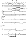
- the heat release is conducted up to the second gradation, and the heat release time control data which are inputted from the controller 24 through the heat release time control buffer 25 to the input terminal A2 of the second comparing means 31 will be assumed to consist of a binary number "10" in all the gradations as shown in Figure 5g.
- the controller 24 decodes and records on the RAM circuit 26 the first line of the image data consisting of a plurality of pixels, and inputs the first line into the input terminal A1 of the first comparing means 31. Under this condition, the controller 24 recognizes the completion of each line and the completion of the total 2 m gradations, and then, reads the output of the A/D converter 23 each time the completion of one line is informed by the block counter 29. Then the controller 24 compares the read data with the image source reference value stored in the RAM circuit 26, and then, sends a heat release control value to the heat release time control buffer 25.
- the image data of the RAM circuit 26 is supplied to the input terminal A1 of the first comparator 31 in the form of a binary number "11" by the help of the function of the clock generating means 16 which is driven by the driving signals of the controller 24. (Refer to Figure 5e).
- the heat release time control buffer 25 which stores the heat release judgment value for the current gradation supplies a binary number "10" to the input terminal A2 of the second comparator 32 (refer to Figure 5g).
- the block counter 29 is driven by the clock generating means 16, and, if pulses are transmitted as much as the number n of the total elements as shown in Figure 5a, then the output of the block counter 29 is transmitted to the gradation counter as shown in Figure 5b, while latch signals are supplied to the TPH 13 at the same time in order to control the TPH as shown in Figure 5k.
- the binary data which is inputted into the input terminal A1 of the first comparator 31 is "11", while the binary data which is inputted into the input terminal A2 of the second comparator 32 is "10". Therefore, the output of the first comparator 31 is maintained in a high level until the third gradation is counted as shown in Figure 5f, while the output is shifted to a low level starting from the fourth gradation.
- the output of the second comparator 32 is maintained in a high level until the second gradation is counted as shown in Figure 5h, while it is shifted to a low level starting from the third gradation.
- the output of the AND gate 33 is maintained in a high level up to the first and second gradations, while it is shifted to a low level from the third gradation to the 2 m th gradation.
- the output of the AND gate 33 is supplied to the TPH 13 only when it is a high level, while the output of the gradation counter 30 is maintained in an active low from the first to 2 m th gradations by supplying strobe signals through the NAND gate as shown in Figure 5j. Therefore, the heat release is conducted up to the second gradation, while the heat release is stopped from the third gradation to the 2 m th gradation.
- the overheating phenomenon which occurs during a printing is detected for each line, and the temperature compensation is carried out for each line. Therefore, the optical concentration which is very sensitive to heat can be more effectively controlled, thereby obtaining a clearer and more uniform picture quality.
- the hardware is constituted in a simpler form, the transmitting speed is increased, and the formation of the control logic circuit is rendered easier.
Landscapes
- Physics & Mathematics (AREA)
- General Physics & Mathematics (AREA)
- Engineering & Computer Science (AREA)
- Automation & Control Theory (AREA)
- Electronic Switches (AREA)
Applications Claiming Priority (2)
| Application Number | Priority Date | Filing Date | Title |
|---|---|---|---|
| KR1019900016774A KR920007816A (ko) | 1990-10-20 | 1990-10-20 | 칼라프린터의 열전사헤드 발열온도 제어장치 |
| KR1677490 | 1990-10-20 |
Publications (1)
| Publication Number | Publication Date |
|---|---|
| EP0482850A2 true EP0482850A2 (fr) | 1992-04-29 |
Family
ID=19304920
Family Applications (1)
| Application Number | Title | Priority Date | Filing Date |
|---|---|---|---|
| EP91309679A Withdrawn EP0482850A2 (fr) | 1990-10-20 | 1991-10-18 | Réglage de température pour une tête d'imprimerie thermique |
Country Status (3)
| Country | Link |
|---|---|
| EP (1) | EP0482850A2 (fr) |
| JP (1) | JPH0624028A (fr) |
| KR (1) | KR920007816A (fr) |
Cited By (6)
| Publication number | Priority date | Publication date | Assignee | Title |
|---|---|---|---|---|
| EP0526884A3 (en) * | 1991-08-05 | 1993-05-26 | Eastman Kodak Company | Thermal printing head |
| EP0730972A3 (fr) * | 1995-03-07 | 1996-12-27 | Francotyp Postalia Ag | Commande thermique d'une tête d'impression |
| US7330201B2 (en) | 2005-09-28 | 2008-02-12 | Eastman Kodak Company | Thermal printer and method for operating same |
| WO2018186862A1 (fr) * | 2017-04-06 | 2018-10-11 | Hewlett-Packard Development Company, L.P. | Caractéristiques de buse |
| CN113815316A (zh) * | 2020-11-26 | 2021-12-21 | 山东华菱电子股份有限公司 | 基于差异化恒流加热的热敏打印头加热控制方法及装置 |
| US11446925B2 (en) | 2017-04-06 | 2022-09-20 | Hewlett-Packard Development Company, L.P. | Fluid supply control |
Families Citing this family (1)
| Publication number | Priority date | Publication date | Assignee | Title |
|---|---|---|---|---|
| US7101099B1 (en) * | 1998-08-19 | 2006-09-05 | Canon Kabushiki Kaisha | Printing head, head cartridge having printing head, printing apparatus using printing head, and printing head substrate |
Family Cites Families (2)
| Publication number | Priority date | Publication date | Assignee | Title |
|---|---|---|---|---|
| JPH01103460A (ja) * | 1987-10-19 | 1989-04-20 | Canon Inc | サーマルヘッド駆動装置 |
| JPH02292061A (ja) * | 1989-04-29 | 1990-12-03 | Nec Home Electron Ltd | サーマルプリンタ |
-
1990
- 1990-10-20 KR KR1019900016774A patent/KR920007816A/ko not_active Withdrawn
-
1991
- 1991-10-18 EP EP91309679A patent/EP0482850A2/fr not_active Withdrawn
- 1991-10-21 JP JP3299626A patent/JPH0624028A/ja active Pending
Cited By (8)
| Publication number | Priority date | Publication date | Assignee | Title |
|---|---|---|---|---|
| EP0526884A3 (en) * | 1991-08-05 | 1993-05-26 | Eastman Kodak Company | Thermal printing head |
| EP0730972A3 (fr) * | 1995-03-07 | 1996-12-27 | Francotyp Postalia Ag | Commande thermique d'une tête d'impression |
| US5838356A (en) * | 1995-03-07 | 1998-11-17 | Francotyp-Postalia Ag & Co. | Print head thermocontrol |
| US7330201B2 (en) | 2005-09-28 | 2008-02-12 | Eastman Kodak Company | Thermal printer and method for operating same |
| WO2018186862A1 (fr) * | 2017-04-06 | 2018-10-11 | Hewlett-Packard Development Company, L.P. | Caractéristiques de buse |
| US11446925B2 (en) | 2017-04-06 | 2022-09-20 | Hewlett-Packard Development Company, L.P. | Fluid supply control |
| US11654678B2 (en) | 2017-04-06 | 2023-05-23 | Hewlett-Packard Development Company, L.P. | Nozzle characteristics |
| CN113815316A (zh) * | 2020-11-26 | 2021-12-21 | 山东华菱电子股份有限公司 | 基于差异化恒流加热的热敏打印头加热控制方法及装置 |
Also Published As
| Publication number | Publication date |
|---|---|
| KR920007816A (ko) | 1992-05-27 |
| JPH0624028A (ja) | 1994-02-01 |
Similar Documents
| Publication | Publication Date | Title |
|---|---|---|
| EP0625425B1 (fr) | Imprimante thermique et méthode d'impression | |
| KR0134341B1 (ko) | 프린터의 용지/필름감지방법 및 그 장치 | |
| US4795999A (en) | Thermal transfer type printer | |
| EP0599127A2 (fr) | Compensation de résistance parasite pour tête d'impression thermique | |
| EP1251682B1 (fr) | Procédé et dispositif d'impression d'image | |
| KR0132896B1 (ko) | 고속 열전사 프린터 | |
| US4786917A (en) | Signal processing for a thermal printer | |
| US4704618A (en) | Signal-processing circuit for heat-sensitive recording apparatus | |
| WO1988010041A2 (fr) | Traitement de signaux pour imprimante thermique | |
| US4590491A (en) | Thermal transfer printer | |
| EP0453714B1 (fr) | Imprimante pour gradation | |
| JPH0624028A (ja) | カラープリンタのtph温度制御装置 | |
| EP0530830B1 (fr) | Imprimante thermique | |
| US5467363A (en) | Laser drive apparatus | |
| US5473355A (en) | Thermal printing method and thermal printer | |
| JP2923958B2 (ja) | 感熱プリンタ | |
| KR0115147Y1 (ko) | 역프린트 기능을 갖는 칼라비디오프린터 | |
| KR0144898B1 (ko) | 고속 열전사 프린터 | |
| EP1133161A2 (fr) | Appareil de formation d'image | |
| KR0132893B1 (ko) | 비디오 프린터장치 | |
| JP2598079B2 (ja) | 中間調記録装置 | |
| JPH0780310B2 (ja) | 熱転写プリンタの記録濃度制御方法 | |
| JPS63166559A (ja) | 感熱式多階調記録装置 | |
| JP2506623B2 (ja) | プリンタにおける階調制御装置 | |
| JPH06205214A (ja) | Ledヘッドの駆動制御回路 |
Legal Events
| Date | Code | Title | Description |
|---|---|---|---|
| PUAI | Public reference made under article 153(3) epc to a published international application that has entered the european phase |
Free format text: ORIGINAL CODE: 0009012 |
|
| AK | Designated contracting states |
Kind code of ref document: A2 Designated state(s): DE FR GB IT |
|
| STAA | Information on the status of an ep patent application or granted ep patent |
Free format text: STATUS: THE APPLICATION HAS BEEN WITHDRAWN |
|
| 18W | Application withdrawn |
Withdrawal date: 19930119 |
|
| RHK1 | Main classification (correction) |
Ipc: G05D 23/19 |
|
| R18W | Application withdrawn (corrected) |
Effective date: 19930119 |