EP0482861B1 - Patrone für hämostatische Klammern - Google Patents
Patrone für hämostatische Klammern Download PDFInfo
- Publication number
- EP0482861B1 EP0482861B1 EP91309705A EP91309705A EP0482861B1 EP 0482861 B1 EP0482861 B1 EP 0482861B1 EP 91309705 A EP91309705 A EP 91309705A EP 91309705 A EP91309705 A EP 91309705A EP 0482861 B1 EP0482861 B1 EP 0482861B1
- Authority
- EP
- European Patent Office
- Prior art keywords
- clip
- cartridge
- pair
- compartment
- walls
- Prior art date
- Legal status (The legal status is an assumption and is not a legal conclusion. Google has not performed a legal analysis and makes no representation as to the accuracy of the status listed.)
- Expired - Lifetime
Links
- 230000002439 hemostatic effect Effects 0.000 title claims abstract description 32
- 239000004033 plastic Substances 0.000 description 7
- 229920003023 plastic Polymers 0.000 description 7
- 230000000717 retained effect Effects 0.000 description 6
- 230000003993 interaction Effects 0.000 description 4
- 239000000463 material Substances 0.000 description 4
- 238000004519 manufacturing process Methods 0.000 description 3
- 230000007246 mechanism Effects 0.000 description 3
- 239000007769 metal material Substances 0.000 description 3
- 238000001356 surgical procedure Methods 0.000 description 3
- 238000003780 insertion Methods 0.000 description 2
- 230000037431 insertion Effects 0.000 description 2
- 230000014759 maintenance of location Effects 0.000 description 2
- 239000002991 molded plastic Substances 0.000 description 2
- 229920000642 polymer Polymers 0.000 description 2
- 238000003860 storage Methods 0.000 description 2
- 240000001492 Carallia brachiata Species 0.000 description 1
- 230000002411 adverse Effects 0.000 description 1
- 210000004204 blood vessel Anatomy 0.000 description 1
- 239000011248 coating agent Substances 0.000 description 1
- 238000000576 coating method Methods 0.000 description 1
- 230000006835 compression Effects 0.000 description 1
- 238000007906 compression Methods 0.000 description 1
- 230000002708 enhancing effect Effects 0.000 description 1
- 230000006355 external stress Effects 0.000 description 1
- 239000010408 film Substances 0.000 description 1
- 229910052588 hydroxylapatite Inorganic materials 0.000 description 1
- 238000000034 method Methods 0.000 description 1
- 238000012986 modification Methods 0.000 description 1
- 230000004048 modification Effects 0.000 description 1
- XYJRXVWERLGGKC-UHFFFAOYSA-D pentacalcium;hydroxide;triphosphate Chemical compound [OH-].[Ca+2].[Ca+2].[Ca+2].[Ca+2].[Ca+2].[O-]P([O-])([O-])=O.[O-]P([O-])([O-])=O.[O-]P([O-])([O-])=O XYJRXVWERLGGKC-UHFFFAOYSA-D 0.000 description 1
- 238000002360 preparation method Methods 0.000 description 1
- 239000011435 rock Substances 0.000 description 1
- 238000006748 scratching Methods 0.000 description 1
- 230000002393 scratching effect Effects 0.000 description 1
- 230000000087 stabilizing effect Effects 0.000 description 1
- 239000010409 thin film Substances 0.000 description 1
Images



Classifications
-
- A—HUMAN NECESSITIES
- A61—MEDICAL OR VETERINARY SCIENCE; HYGIENE
- A61B—DIAGNOSIS; SURGERY; IDENTIFICATION
- A61B17/00—Surgical instruments, devices or methods
- A61B17/08—Wound clamps or clips, i.e. not or only partly penetrating the tissue ; Devices for bringing together the edges of a wound
-
- A—HUMAN NECESSITIES
- A61—MEDICAL OR VETERINARY SCIENCE; HYGIENE
- A61B—DIAGNOSIS; SURGERY; IDENTIFICATION
- A61B17/00—Surgical instruments, devices or methods
- A61B17/12—Surgical instruments, devices or methods for ligaturing or otherwise compressing tubular parts of the body, e.g. blood vessels or umbilical cord
- A61B17/122—Clamps or clips, e.g. for the umbilical cord
- A61B17/1222—Packages or dispensers therefor
Definitions
- the invention relates generally to holders for storing and retaining hemostatic clips prior to use. More particularly, the invention relates to hemostatic clip cartridges which facilitate the storage and retention of a plurality of hemostatic clips within a corresponding plurality of individual chambers of the cartridge prior to withdrawal of the clips by a forceps-type clip applier.
- Hemostatic clips have long been used to ligate or clamp blood vessels during surgical procedures.
- the clips are generally made of either a biocompatible metallic material or of a polymeric or non- metallic material.
- non-metallic as used herein means anything other than metallic materials.
- the clips are generally C-shaped, U-shaped or V-shaped and are designed such that the opposing legs of the open clip are able to be closed together by being compressed by the jaws of a forceps-type clip applier.
- the material is sufficiently strong such that the clips remain in their crimped, closed position merely by squeezing the legs together.
- plastics-type clips the material is not as strong and requires some auxiliary latching mechanism to keep the clips closed.
- the latching mechanism generally comprises a hook-type arrangement molded with or otherwise secured to the plastics clip.
- the plastics ligating clip is shown in our U.S. Patent 4,834,096 (Oh et al.).
- clip cartridges intended for use with "manual” clip appliers and those intended for use with “automatic” clip appliers.
- automatic means those clip appliers which retain a plurality of hemostatic clips adjacent the jaws of a clip applier in a way such that a new clip is automatically fed to the jaws after the previous clip has been crimped into place.
- the term "manual" means clip appliers which receive one clip at a time between the jaws and which have to be reloaded manually after the previous clip is crimped.
- the reloading operation is generally accomplished by inserting the jaws of the applier into a clip holder or cartridge which is generally provided with a plurality of longitudinally spaced, clip retaining chambers.
- a single clip is retained in each chamber by a variety of means and removed from its chamber by a forceps-type clip applier which is inserted as desired into each clip chamber and secured to the clip sufficiently to overcome whatever clip retention means is utilized, to enable the clip to be removed from the clip chamber.
- clips may be retained within the chambers of clip cartridges.
- friction between the clip and the side walls or its individual chamber is generally sufficient to retain the clip.
- the clip cartridges are generally made of molded plastics material such that the walls of each clip chamber are somewhat resilient and able to be pushed away from each other when the clip applier jaws are inserted into the chamber to retrieve the clip.
- An example of a cartridge holding the clips in their respective clip chambers by means of frictional engagement with the side walls of each chamber is shown in U.S. Patent 4,076,120 (Carroll et al.).
- each individual clip chamber is provided with a central post generally conforming to the shape of the open clip although being slightly larger so that when the clip is pushed onto the central post, frictional contact between the legs of the clip and the central post retains the clip within its chamber.
- Cartridges of this type are shown in U.S. Patent Nos. 3,270,745 3,326,216, 3,363,628, 3,439,522 and 3,439,523, all issued to E.C. Wood.
- Prior art cartridges which retain clips in a partially straightened state by maintaining each clip under tension within its chamber by the interaction between the central post in the chamber and the central part of the clip and protrusions extending into each chamber toward the central post (from the ends).
- the clip is retained by having its central hinge part pushed upwardly by the central post and its ends pushed downwardly by the protrusions.
- U.S. Patent 3,713,533 Reimels
- U.S. Patent 4,146,130 Standarduels et al.
- the prior art cartridges suitable for holding metallic clips are not necessarily suitable because the plastics clips inherently have a greater resiliency and non-symmetrical structure.
- the aforementioned prior art cartridges which rely on the interaction between the clip and central post are not suitable for use with non-metallic clips because there is generally insufficient compression in non-metallic clips to cause them to grip the center post adequately.
- frictional engagement with the side and/or end walls of the chamber could possibly, over a long period of storage time, adversely affect performance of the clips. It would be preferable to retain non-metallic clips in a natural, relaxed state without any external stress applied to the clips until they are ready for use.
- U.S. Patent 4,294,355 discloses one or more resilient fingers associated with each clip chamber for holding each clip in a particular fixed orientation.
- the entire cartridge may or may not be covered by a thin film having a plurality of lines of weakness over each clip to identify the clip location for easy retrieval by the clip applier.
- U.S. Patent 4,361,229 discloses a cartridge for non-metallic clips wherein each clip is retained in its individual chamber by the interaction between a central post supporting each clip and paper flaps extending into each end of each chamber, the paper flaps being formed from a paper film interposed between a base portion of the cartridge (to which the central post is secured) and a top portion.
- U.S. Patent 4961499 discloses a cartridge for retaining hemostatic clips in combination with a hemostatic clip having a body including a hinge portion, the cartridge comprising:
- the invention also provides a holder for holding a hemostatic clip in combination with a hemostatic clip having a body including a hinge portion, the holder comprising:
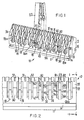
- FIG. 1 there is shown a preferred embodiment of the clip cartridge 10 constructed in accordance with the principles of this invention.
- Clip cartridge 10 is a single molded plastics component comprising a plurality of longitudinally spaced, individual clip retaining chambers 18, each of which is identical and retains a clip 20 (only one of which is shown).
- Clip 20 is a non-symmetrical hemostatic clip of the type shown in U.S. Patent 4,834,096 (Oh et al.). As best seen in Figures 1 and 10-13 and in the aforementioned '096 patent, clip 20 comprises an integral plastics C-shaped body 4 with two legs hinged at a central point and a pair of lateral engagement means or bosses 6 and 8 near the ends of the legs. As will be understood below, bosses 6 and 8 interact with portions of cartridge 10.
- Cartridge 10 has a base portion 11, a body portion 12 and a neck portion 13 interposed between the body and base in order to define channels 14 and 15 which serve to facilitate securing the cartridge to a tray or other component during use. It will be noted that cartridge 10 is symmetrical about its longitudinal centerline and this facilitates its manufacture as well as its assembly with clips 20. The jaw portion of a representative clip applier 22 is diagrammatically shown in position over clip 20 in one of the clip chambers 18.
- adjacent clip chambers 18 are separated by transverse walls 30 which (at their bases) extend across the width or body 12 (best seen in Figure 4).
- the end clip chambers 18a obviously have a wall 30 only on one side and are bounded on the opposite side by end wall portions 34 and 35 of body 12, as the case may be. These end wall portions have some similarity to walls 30 in order to insure that end chambers 18a are identical in operation to intermedicate chamber 18.
- Each wall 30 and end walls 34 and 35 have a transverse slit 31 near their upper ends, the purpose of which will be discussed below.
- the upper suface of each wall 30 is tapered at 32 and 33 to reduce cartridge mass and improves the accessibility of the clips.
- Each wall 30 has a pair of symmetrical and oppositely facing transverse wall surfaces 40 and 50 which form the sides of each chamber 18: surface 40 facing inwardly into one clip chamber 18 and surface 50 facing inwardly into an adjacent clip chamber 18.
- the wall surfaces facing to the right in Figure 2 are each identified as 40 and those facing to the left are each identified as 50.
- Each clip chamber 18 is also provided with an integral central post 23, interposed between facing wall surfaces 40 and 50, and has floor portions 24a and 24b on either side of the post.
- Wall surfaces 40 and 50 are formed by a variety of facing symmetrical and parallel wall and ledge surfaces, best seen in Figures 2, 3 and 4 and described below. In view of the symmetrical nature of cartridge 10 and facing wall surfaces 40 and 50, for simplicity only the features of one clip chamber 18 will be described in detail.
- Wall surface 50 is shown in detail in Figure 4, but it will be understood that the features of wall surface 50 have symmetrical counterparts on wall surface 40.
- Wall surface 50 includes a main portion 52 which is spaced from its symmetrical facing surface 42 by an amount slightly greater than the width of the body 4 of clip 20 to be received in chamber 18.
- Wall surface 50 has recessed wall portions 54 and 56 symmetrically arranged on either side of main portion 52, and wall surface 40 has facing recessed wall portions 44 and 46. The distance between facing surfaces 44/54 and 46/56 is greater than the spacing between facing main portions 42 and 52.
- Surfaces 40 and 50 may have any variety of selected profiles; however, in a preferred embodiment the recesses 54, 56 and 44, 46 do not extend entirely across the width of body 12 or to the bottom of channel 18, thereby forming bottom ledges 57, 58 and 46, 48 parallel to and on either side of the floor 24a/24b of each chamber 18.
- the inner ends of ledges 57, 58 and 47, 48 are each angled inwardly and upwardly to form inclined ramps 60, 61, 70 and 71, respectively, which merge into flat ledges 62, 63 and 72, 73, respectively.
- the profile of recesses 54, 56 and 44, 46 continues upwardly from the inner edges of ledges 62, 63 and 72, 73 to form vertical ledges 64, 65 and 74, 75 at the upper ends of which recesses 54, 56 extend diagonally upwardly and outwardly to form ledges 66, 67 and 76, 77 and then upwardly to form ledges 68, 69 and 78, 79 to the top of body 12.
- the ledges 62, 64, 66 and 63, 65, 67 form recesses 90 and 91 which, as will be seen in Figures 10a and 10b, receive lateral boss 6 to allow clip 20 to balance itself on post 23. (Wall 40 has a symmetrical pair of recesses 92 and 93.)
- an alternative embodiment 10' may be made in which bottom ledges 57, 60, 62 and 58, 61, 63 are replaced by straight ledges 57' and 58', respectively, all other parts of cartridge 10' being identical to cartridge 10.
- the various ledges in each clip chamber 18 may be shaped differently to accommodate different clip structures and to conform to various shapes of clip applier tips.
- an alternative embodiment 10'' may be made in which ledges 57' and 58' may also be modified to produce facing steps 57'' and 58'' to provide clearance for projecting sharp distal points of clip 20 as it is compressed by the applier jaws.
- Ledge pairs 68/78 and 69/79 on either side of center post 23 serve as guides to center a clip applier as it enters chamber 18 to ensure proper insertion of the clip into the applier jaws as will be better seen in Figures 11-13.
- the bottommost ledges in the various embodiments primarily serve as a stop for the downward movement of the applier into the cartridge.
- Ledges 60, 61 and 70, 71 also serve to center the particular jaw tips shown in Figures 11-13.
- protrusions 81 and 82 Spaced above the upper tip 80 of central post 23 are inwardly directed, facing and symmetrical protrusions 81 and 82 integrally formed near the apices of surfaces 40 and 50, respectively.
- Protrusions 81 and 82 serve as clip retaining means by slightly narrowing the distance between faces 40 and 50 in part of the area above central post 23.
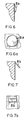
- protrusions 81, 82 may be formed in a variety of shapes, 81a, 81b, 81c and 81d, all integrally molded with surfaces 40 and 50.
- Central post 23 is provided with a pair of opposed recesses 84 and 85 to accommodate the hook end of clip 20 to enable the clip to balance itself on the post (as best seen in Figures 10a and 10b).
- cartridge 10 facilitates its use with non-symmetrical polymeric hemostatic clips 20 of the type shown in the aforementioned U.S. Patent 4,834,096.
- cartridge 10 would also be suitable for symmetrical metallic or non-metallic clips.
- the provision of a narrow central post 23 and a pair of retaining means 81 and 82 spaced above the post so as not to directly press inwardly on the body of clip 20 enables the clip to rock somewhat about the tip of central post 23 thereby facilitating its subsequent retrieval by clip applier 22 as best seen in Figures 11, 12 and 13.
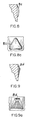
- the recesses on either side of post 23 accommodate the hook end of clip 20 regardless of whether the hook is on the left ( Figure 10a) or right ( Figure 10b).
- the recesses 90, 91 serve to receive the lateral bosses of the particular clip shown in the aforementioned patent. This symmetry facilitates loading clips into the cartridge because particular attention need not be paid to whether the clips are facing right or left.
- clip 20 will be forced to pivot about the tip of center post 23 thereby insuring that the lateral latching means on each leg of the clip will be properly aligned and placed adjacent to the corresponding recesses 96, 97 on the clip jaws.
- the interaction between the lateral bosses on each leg of the clip and the recesses on each jaw of the clip applier causes the clip to be compressed slightly and causes the lateral bosses on the clip to become seated in the recesses of the jaws of the applier.
- slight upward movement of the applier from the position shown in Figure 13 will cause clip 22 to ride over protrusions 81 and 82, the deflection of which is facilitated by slit 31, thereby removing the clip from its chamber.
- FIG. 15 through 20 there is shown an alternative embodiment of the invention in the form of clip cartridge 100 having a plurality of longitudinally spaced clip chambers 118 for retaining hemostatic clips 120.
- the invention is suitable for use with metallic and non-metallic hemostatic clips and cartridge 120 is described in conjunction with metallic hemostatic clip 120 which may or may not be coated with hydroxyapatite or some other grasping enhancing material.
- Cartridge 100 is suitable for use in the situation where coated metallic clips are utilized and it is desired to provide a clip cartridge which retains the clip in a manner which significantly reduces any likelihood of scratching or otherwise maring the coating.
- Each chamber 118 has opposed and inwardly extending projections 182, best seen in Figures 15 and 16 protrusions 182 operate in conjunction with center post 123 in the same manner as the previously described embodiments.
- center post 123 has a pair of opposed and outwardly extending projections 125, 127 situated adjacent the base of each center post 123, the projections intended to lie adjacent the ends of the legs of clip 120 (as best seen in Figure 17) to assist in stabilizing the clip.
- center post 123 may be provided in alternative embodiments 123A and 123B in order to provide different degrees of support and stability for clip 120.
- each clip chamber 118 is provided with a pair of forceps receiving channels 130 and 132 for receiving the jaws of an associated forceps-type clip applier which may be inserted into each clip chamber 118 to retrieve the clip situated therein.
- the longitudinally extending vertical ledges 134 and 136 help to align the clip applier as it is inserted into clip chamber 118 so that the applier may properly engage clip 120.
Landscapes
- Health & Medical Sciences (AREA)
- Surgery (AREA)
- Life Sciences & Earth Sciences (AREA)
- Heart & Thoracic Surgery (AREA)
- Molecular Biology (AREA)
- Veterinary Medicine (AREA)
- Engineering & Computer Science (AREA)
- Biomedical Technology (AREA)
- Public Health (AREA)
- Medical Informatics (AREA)
- Nuclear Medicine, Radiotherapy & Molecular Imaging (AREA)
- Animal Behavior & Ethology (AREA)
- General Health & Medical Sciences (AREA)
- Reproductive Health (AREA)
- Vascular Medicine (AREA)
- Surgical Instruments (AREA)
- Materials For Medical Uses (AREA)
- Medicines Containing Material From Animals Or Micro-Organisms (AREA)
Claims (9)
- Patrone (10; 100) zum Halten von hämostatischen Klammern in Kombination mit einer hämostatischen Klammer (20; 120), die einen Körper mit einem Gelenkteil hat, wobei die Patrone aufweist:einen Körperteil (12) mit einer Vielzahl von Klammerhalteabteilen (18; 118), die längs entlang diesem Körperteil (12) im Abstand angeordnet sind, wobei jedes Abteil (18; 118) durch ein Paar von sich nach oben erstreckenden Wänden (30) gebildet ist, jedes Abteil einen zentralen Ständer (23; 123; 123A; 123B) zum Stützen des Gelenkteiles der Klammer (20; 120) hat und angrenzend an das entfernte Ende der Wände (30) mit einem Paar von entgegengesetzten, sich nach innen erstreckenden Vorsprüngen (81, 82; 81a; 81b; 81c; 81d; 182) versehen ist, wobei sich ein Vorsprung nach innen von jeder Wand (30) erstreckt, jedes Paar der Vorsprünge so angeordnet ist, daß es sich in das zugeordnete Abteil (18; 118) über der Klammer (20; 120) erstreckt, und so angeordnet ist, daß es durch die Klammer (20; 120) gebogen wird, wenn sie dem Abteil (18; 118) entnommen wird;dadurch gekennzeichnet, daß die Vorsprünge (81, 82; 81a; 81b; 81c; 81d; 182) im Abstand über dem Ständer (23; 123; 123A; 123B) so angeordnet sind, daß sie nicht direkt nach innen auf den Körper der Klammer (20; 120) drücken.
- Patrone nach Anspruch 1, wobei die angrenzenden, sich nach oben erstreckenden Wände (30), welche die angrenzenden Abteile (18; 118) bilden, einstückig miteinander verbunden sind.
- Patrone nach Anspruch 2, wobei ein Querschlitz (31) in den einstückig verbundenen Wänden (20) hinter dem diesen zugeordneten Vorsprung (81, 82; 81a; 81b; 81c; 81d; 182) gebildet ist.
- Patrone nach Anspruch 1, 2 oder 3, wobei der Körperteil (12) einstückig mit den Wänden (30) und den Vorsprüngen (81, 82; 81a; 81b; 81c: 81d; 182) geformt ist.
- Patrone nach Anspruch 4, die ferner einen Basisteil (11) aufweist, der einstückig mit dem Körperteil (12) gebildet und von ihm im Abstand angeordnet ist, um ein Paar von parallelen, sich längs erstreckenden Kanälen (14, 15) zur Befestigung der Patrone an einem komplementär geformten Rahmenmittel zu bilden.
- Patrone nach einem vorhergehenden Anspruch, wobei das Wandpaar ein Paar von einanderzugekehrten, symmetrischen, quergerichteten Wandoberflächen (40, 50) ist, die sich über den Körperteil (12) erstrecken, wobei jede der quergerichteten Wandoberflächen (40, 50) ein Paar von ausgesparten Wandoberflächen (54, 56) auf den betreffenden Seiten jedes zentralen Ständers (23; 123; 123A; 123B) hat, wobei die quergerichteten Wandoberflächen (52) und die ausgesparten Wandoberflächen (54, 56) durch sich längs erstreckende Leistenoberflächen (57, 60, 62, 64, 66, 68, 58, 61, 63, 65, 67, 69) verbunden sind.
- Patrone nach Anspruch 6, wobei der zentrale Ständer (23; 123; 123A; 123B) sich symmetrisch in einer Querrichtung befindet und in einem vorbestimmten Abstand von der Spitze (80) des Ständers ein Paar von sich gegenüberliegenden Ausnehmungen (84, 85) hat.
- Patrone nach Anspruch 6 oder 7, wobei die Leistenoberflächen ein Paar von im wesentlichen vertikalen Leisten (68, 69) auf den jeweiligen Seiten des Ständers aufweisen, um die Backen (96, 97) einer zugeordneten Klammerbetätigungsvorrichtung in Eingriff mit der Klammer (20; 120) zu führen.
- Haltevorrichtung (10; 100) zum Halten einer hämostatischen Klammer in Kombination mit einer hämostatischen Klammer (20; 120), die einen Körper mit einem Gelenkteil hat, wobei die Haltevorrichtung aufweist:einen Körperteil (12) mit einem Klammerhalteabteil (18; 118), das durch ein Paar von sich nach oben erstreckenden Wänden (30) gebildet ist, wobei das Abteil einen zentralen Ständer (23; 123; 123A; 123B) zum Stützen des Gelenkteils einer Klammer (20; 120) hat und angrenzend an das entfernte Ende der Wände (30) mit einem Paar von gegenüberliegenden, sich nach innen erstreckenden Vorsprüngen (81, 82; 81a; 81b; 81c; 81d; 182) versehen ist, wobei sich ein Vorsprung nach innen von jeder Wand (30) erstreckt, jedes Paar dieser Vorsprünge so angeordnet ist, daß es sich in das Abteil (18; 118) über der Klammer (20; 120) erstreckt und angeordnet ist, um durch die Klammer (20; 120) gebogen zu werden, wenn sie dem Abteil (18; 118) entnommen wird;dadurch gekennzeichnet, daß die Vorsprünge (81, 82; 81a; 81b; 81c; 81d; 182) über dem Ständer (23; 123; 123A; 123B) so im Abstand angeordnet sind, daß sie nicht direkt nach innen auf den Körper der Klammer (20; 120) drucken.
Applications Claiming Priority (2)
| Application Number | Priority Date | Filing Date | Title |
|---|---|---|---|
| US601833 | 1990-10-22 | ||
| US07/601,833 US5201416A (en) | 1990-10-22 | 1990-10-22 | Hemostatic clip cartridge |
Publications (2)
| Publication Number | Publication Date |
|---|---|
| EP0482861A1 EP0482861A1 (de) | 1992-04-29 |
| EP0482861B1 true EP0482861B1 (de) | 1997-03-05 |
Family
ID=24408950
Family Applications (1)
| Application Number | Title | Priority Date | Filing Date |
|---|---|---|---|
| EP91309705A Expired - Lifetime EP0482861B1 (de) | 1990-10-22 | 1991-10-21 | Patrone für hämostatische Klammern |
Country Status (12)
| Country | Link |
|---|---|
| US (1) | US5201416A (de) |
| EP (1) | EP0482861B1 (de) |
| JP (1) | JP3249554B2 (de) |
| KR (1) | KR920007604A (de) |
| AT (1) | ATE149315T1 (de) |
| AU (1) | AU8598891A (de) |
| CA (1) | CA2053775A1 (de) |
| DE (1) | DE69124914T2 (de) |
| ES (1) | ES2098331T3 (de) |
| IE (1) | IE913679A1 (de) |
| NO (1) | NO914138L (de) |
| ZA (1) | ZA918299B (de) |
Cited By (3)
| Publication number | Priority date | Publication date | Assignee | Title |
|---|---|---|---|---|
| DE102011056821A1 (de) * | 2011-12-21 | 2013-06-27 | Aesculap Ag | Medizinische Clipträgervorrichtung |
| CN111200977A (zh) * | 2017-11-03 | 2020-05-26 | 柯惠Lp公司 | 模块式手术夹具器 |
| US11432823B2 (en) | 2019-07-17 | 2022-09-06 | Grena Usa Llc | Ligating clip cartridge |
Families Citing this family (46)
| Publication number | Priority date | Publication date | Assignee | Title |
|---|---|---|---|---|
| CA2101611A1 (en) * | 1992-08-12 | 1994-02-13 | Warren Taylor | Hemostatic clip cartridge with clip retaining means |
| US5908430A (en) * | 1995-06-07 | 1999-06-01 | Appleby; Timothy | Easy loading hemostatic clip and cartridge |
| AUPN562295A0 (en) * | 1995-09-26 | 1995-10-19 | Compton, Jeffrey Spencer Dr | Easy load device for raney style scalp clips |
| AU699038B2 (en) * | 1995-09-26 | 1998-11-19 | Compton, Jeffrey Spencer | A surgical clip set |
| FR2751863B1 (fr) * | 1996-08-01 | 1999-01-22 | Vitalitec International | Support de clips hemostatiques |
| US6044971A (en) | 1997-10-10 | 2000-04-04 | United States Surgical Corporation | Clip cartridge |
| DE19903752C1 (de) * | 1999-01-30 | 2000-03-30 | Aesculap Ag & Co Kg | Magazin zur Aufnahme von Clips |
| US6273253B1 (en) | 2000-07-07 | 2001-08-14 | Vitalitec International, Inc. | Cartridge and system for holding and applying clips |
| US6880699B2 (en) * | 2002-08-27 | 2005-04-19 | Pilling Weck Incorporated | Cartridge for holding asymmetric surgical clips |
| US9445820B2 (en) | 2007-12-31 | 2016-09-20 | Teleflex Medical Incorporated | Ligation clip with flexible clamping feature |
| DE102008018158A1 (de) * | 2008-04-10 | 2009-10-15 | Aesculap Ag | Ligaturklammermagazin und Lagerkörper zur Verwendung in diesem |
| DE102009035756A1 (de) | 2009-07-24 | 2011-01-27 | Aesculap Ag | Clipträgervorrichtung |
| US10136898B2 (en) | 2010-03-09 | 2018-11-27 | Teleflex Medical Incorporated | Narrow profile surgical ligation clip |
| EP2755578A2 (de) | 2011-09-15 | 2014-07-23 | Teleflex Medical Incorporated | Manueller chirurgischer ligationsclipapplikator |
| WO2013059826A1 (en) | 2011-10-20 | 2013-04-25 | Atsina Surgical, Llc | Ligation clip |
| EP3328295B1 (de) * | 2015-07-30 | 2021-05-05 | Teleflex Medical Incorporated | Schnappbare chirurgische clipkassette |
| CN105054978B (zh) * | 2015-08-26 | 2017-09-19 | 中国人民解放军南京军区福州总医院 | 弹链式连发填充止血式穿刺针及卡扣 |
| CA3032824C (en) | 2016-08-03 | 2021-04-27 | Teleflex Medical Incorporated | Surgical ligation clip |
| CN110740696B (zh) | 2017-03-21 | 2023-04-07 | 泰利福医疗公司 | 具有稳定构件的施夹器 |
| US11534177B2 (en) | 2017-03-21 | 2022-12-27 | Teleflex Medical Incorporated | Flexible stabilizing member for a clip applier |
| WO2018175610A1 (en) | 2017-03-21 | 2018-09-27 | Teleflex Medical Incorporated | Surgical clip and clip applier |
| US12023041B2 (en) | 2017-03-21 | 2024-07-02 | Teleflex Medical Incorporated | Clip applier |
| US11266408B2 (en) | 2017-03-21 | 2022-03-08 | Teleflex Medical Incorporated | Clip applier having stabilizing member |
| EP3641667A4 (de) | 2017-06-22 | 2021-03-10 | Teleflex Medical Incorporated | Chirurgische klammer |
| US20190133590A1 (en) | 2017-11-03 | 2019-05-09 | Covidien Lp | Ligation clip with controlled tissue compression |
| CN117357190A (zh) | 2017-11-14 | 2024-01-09 | 泰利福医疗公司 | 手术夹 |
| US10932789B2 (en) | 2018-04-11 | 2021-03-02 | Covidien Lp | Ligation clip with latching and retention features |
| US10932788B2 (en) | 2018-04-11 | 2021-03-02 | Covidien Lp | Ligation clip with latching and retention features |
| US11033279B2 (en) | 2018-04-24 | 2021-06-15 | Covidien Lp | Ligation clip with retention features |
| US11304703B2 (en) | 2018-05-25 | 2022-04-19 | Covidien Lp | Ligation clip removal device |
| US11317923B2 (en) | 2018-08-13 | 2022-05-03 | Covidien Lp | Ligation clip with improved hinge |
| US11304704B2 (en) | 2018-08-22 | 2022-04-19 | Covidien Lp | Surgical clip applier and ligation clips |
| CN112867451B (zh) | 2018-09-26 | 2025-06-06 | 泰利福医疗公司 | 具有稳定构件的施夹器 |
| US11471165B2 (en) | 2019-05-08 | 2022-10-18 | Covidien Lp | Ligation clip cartridge |
| US11707282B2 (en) | 2019-07-02 | 2023-07-25 | Covidien Lp | Multi-piece ligation clip |
| USD907203S1 (en) | 2019-08-02 | 2021-01-05 | Covidien Lp | Ligation clip |
| USD907204S1 (en) | 2019-08-02 | 2021-01-05 | Covidien Lp | Ligation clip |
| US11395660B2 (en) | 2019-08-05 | 2022-07-26 | Covidien Lp | Stackable ligation clip |
| USD907200S1 (en) | 2019-08-05 | 2021-01-05 | Covidien Lp | Ligation clip |
| WO2021062170A1 (en) | 2019-09-26 | 2021-04-01 | Teleflex Medical Incorporated | Clip applier |
| CN114929119A (zh) | 2019-12-19 | 2022-08-19 | 泰利福医疗公司 | 手术夹具 |
| US11779340B2 (en) * | 2020-01-02 | 2023-10-10 | Covidien Lp | Ligation clip loading device |
| US11696764B2 (en) | 2020-01-31 | 2023-07-11 | Covidien Lp | Ligation clip with controlled tissue compression |
| US12114866B2 (en) | 2020-03-26 | 2024-10-15 | Covidien Lp | Interoperative clip loading device |
| US11812966B2 (en) | 2020-04-24 | 2023-11-14 | NeuraMedica Inc. | Clips, appliers, and cartridges |
| KR20240006062A (ko) | 2021-05-07 | 2024-01-12 | 텔리플렉스 메디컬 인코포레이티드 | 외과용 클립을 언래칭하기 위한 장치 및 방법 |
Family Cites Families (10)
| Publication number | Priority date | Publication date | Assignee | Title |
|---|---|---|---|---|
| US3270745A (en) * | 1963-06-11 | 1966-09-06 | Rene G Le Vaux | Hemostatic clip constructions |
| US3351191A (en) * | 1965-09-30 | 1967-11-07 | Codman & Shurtleff | Surgical staple cartridge |
| GB1309342A (en) * | 1971-02-16 | 1973-03-07 | Eadie Bros & Co Ltd | Devices for holding travellers for use on rings of ring spinning twisting doubling and like frames |
| US4076120A (en) * | 1976-12-10 | 1978-02-28 | American Hospital Supply Corporation | Cartridge for holding hemostatic clips |
| US4212390A (en) * | 1977-10-20 | 1980-07-15 | Propper Manufacturing Co., Inc. | Wound clip rack |
| US4294355A (en) * | 1979-12-06 | 1981-10-13 | Ethicon, Inc. | Cartridge for hemostatic clips |
| US4412617A (en) * | 1981-07-20 | 1983-11-01 | Ethicon, Inc. | Ligating clip package |
| GB8417562D0 (en) * | 1984-07-10 | 1984-08-15 | Surgical Design Services | Fasteners |
| US4696396A (en) * | 1985-12-19 | 1987-09-29 | Samuels Peter B | Hemostatic clip cartridge |
| US4961499A (en) * | 1990-01-04 | 1990-10-09 | Pilling Co. | Hemostatic clip cartridge |
-
1990
- 1990-10-22 US US07/601,833 patent/US5201416A/en not_active Expired - Lifetime
-
1991
- 1991-10-17 ZA ZA918299A patent/ZA918299B/xx unknown
- 1991-10-21 NO NO91914138A patent/NO914138L/no unknown
- 1991-10-21 ES ES91309705T patent/ES2098331T3/es not_active Expired - Lifetime
- 1991-10-21 EP EP91309705A patent/EP0482861B1/de not_active Expired - Lifetime
- 1991-10-21 DE DE69124914T patent/DE69124914T2/de not_active Expired - Lifetime
- 1991-10-21 AU AU85988/91A patent/AU8598891A/en not_active Abandoned
- 1991-10-21 IE IE367991A patent/IE913679A1/en not_active Application Discontinuation
- 1991-10-21 AT AT91309705T patent/ATE149315T1/de not_active IP Right Cessation
- 1991-10-22 KR KR1019910018579A patent/KR920007604A/ko not_active Withdrawn
- 1991-10-22 CA CA002053775A patent/CA2053775A1/en not_active Abandoned
- 1991-10-22 JP JP27404291A patent/JP3249554B2/ja not_active Expired - Fee Related
Cited By (4)
| Publication number | Priority date | Publication date | Assignee | Title |
|---|---|---|---|---|
| DE102011056821A1 (de) * | 2011-12-21 | 2013-06-27 | Aesculap Ag | Medizinische Clipträgervorrichtung |
| CN111200977A (zh) * | 2017-11-03 | 2020-05-26 | 柯惠Lp公司 | 模块式手术夹具器 |
| CN111200977B (zh) * | 2017-11-03 | 2023-11-14 | 柯惠Lp公司 | 模块式手术夹具器 |
| US11432823B2 (en) | 2019-07-17 | 2022-09-06 | Grena Usa Llc | Ligating clip cartridge |
Also Published As
| Publication number | Publication date |
|---|---|
| NO914138D0 (no) | 1991-10-21 |
| CA2053775A1 (en) | 1992-04-23 |
| DE69124914T2 (de) | 1997-06-19 |
| EP0482861A1 (de) | 1992-04-29 |
| US5201416A (en) | 1993-04-13 |
| IE913679A1 (en) | 1992-04-22 |
| AU8598891A (en) | 1992-04-30 |
| ES2098331T3 (es) | 1997-05-01 |
| NO914138L (no) | 1992-04-23 |
| KR920007604A (ko) | 1992-05-27 |
| ATE149315T1 (de) | 1997-03-15 |
| ZA918299B (en) | 1992-06-24 |
| JPH06339482A (ja) | 1994-12-13 |
| JP3249554B2 (ja) | 2002-01-21 |
| DE69124914D1 (de) | 1997-04-10 |
Similar Documents
| Publication | Publication Date | Title |
|---|---|---|
| EP0482861B1 (de) | Patrone für hämostatische Klammern | |
| US5279416A (en) | Ligating device cartridge with separable retainer | |
| US6880699B2 (en) | Cartridge for holding asymmetric surgical clips | |
| KR930002827B1 (ko) | 지혈 클립 카트리지 | |
| US4972949A (en) | Hemostatic clip holder for small clips | |
| EP0087938B1 (de) | Gerät zum Anbringen von Ligaturklammern mit ausgerichteter Patrone und Zufuhrmechanismus dessen Druck unterbrochen ist | |
| US4936447A (en) | Hemostatic clip holder | |
| US4696396A (en) | Hemostatic clip cartridge | |
| US8403138B2 (en) | Surgical clip cartridge and housing member for use therein | |
| US20020046961A1 (en) | Surgical clip holder and method therefor | |
| US6419682B1 (en) | Hemostatic clip cartridge | |
| US4971198A (en) | Hemostatic clip and cartridge assembly | |
| US4530445A (en) | Paper clip holder | |
| US3086208A (en) | Surgical clip assembly | |
| EP0087939B1 (de) | Gerät zum Anbringen von Ligaturklammern versehen mit einem eine Zickzack-Feder aufweisenden Zufuhrmechanismus | |
| EP0072171A2 (de) | Patrone für Lingaturklammern | |
| JP2000515047A (ja) | 止血クリップ支持具 | |
| EP0087940A2 (de) | Abbindungsklammer und Gerät zu deren Anbringen versehen mit einer mit der Klammer zusammenwirkenden Hemmung | |
| EP0583151A1 (de) | Aufbewahrungssystem für häemostatische Klammern mit Klammerhaltemitteln | |
| US5040676A (en) | Container and dispenser for an aneurysm clip | |
| CN216167662U (zh) | 一种夹仓、夹仓装置和施夹器 | |
| CN211534631U (zh) | 一次性组织闭合夹底座 | |
| JPS5951297B2 (ja) | 止血用クリツプ保持具 | |
| US5666983A (en) | Apparatus for using beaded dental floss | |
| EP0338754A2 (de) | Hämostatische Klammerpatrone |
Legal Events
| Date | Code | Title | Description |
|---|---|---|---|
| PUAI | Public reference made under article 153(3) epc to a published international application that has entered the european phase |
Free format text: ORIGINAL CODE: 0009012 |
|
| AK | Designated contracting states |
Kind code of ref document: A1 Designated state(s): AT BE CH DE DK ES FR GB GR IT LI LU NL SE |
|
| 17P | Request for examination filed |
Effective date: 19921022 |
|
| 17Q | First examination report despatched |
Effective date: 19940915 |
|
| RAP1 | Party data changed (applicant data changed or rights of an application transferred) |
Owner name: PILLING WECK INCORPORATED |
|
| GRAG | Despatch of communication of intention to grant |
Free format text: ORIGINAL CODE: EPIDOS AGRA |
|
| GRAH | Despatch of communication of intention to grant a patent |
Free format text: ORIGINAL CODE: EPIDOS IGRA |
|
| GRAH | Despatch of communication of intention to grant a patent |
Free format text: ORIGINAL CODE: EPIDOS IGRA |
|
| GRAA | (expected) grant |
Free format text: ORIGINAL CODE: 0009210 |
|
| ITF | It: translation for a ep patent filed | ||
| AK | Designated contracting states |
Kind code of ref document: B1 Designated state(s): AT BE CH DE DK ES FR GB GR IT LI LU NL SE |
|
| PG25 | Lapsed in a contracting state [announced via postgrant information from national office to epo] |
Ref country code: AT Effective date: 19970305 Ref country code: NL Free format text: LAPSE BECAUSE OF FAILURE TO SUBMIT A TRANSLATION OF THE DESCRIPTION OR TO PAY THE FEE WITHIN THE PRESCRIBED TIME-LIMIT Effective date: 19970305 Ref country code: GR Free format text: LAPSE BECAUSE OF FAILURE TO SUBMIT A TRANSLATION OF THE DESCRIPTION OR TO PAY THE FEE WITHIN THE PRESCRIBED TIME-LIMIT Effective date: 19970305 Ref country code: DK Effective date: 19970305 |
|
| REF | Corresponds to: |
Ref document number: 149315 Country of ref document: AT Date of ref document: 19970315 Kind code of ref document: T |
|
| REG | Reference to a national code |
Ref country code: CH Ref legal event code: EP Ref country code: CH Ref legal event code: NV Representative=s name: MICHELI & CIE INGENIEURS-CONSEILS |
|
| REF | Corresponds to: |
Ref document number: 69124914 Country of ref document: DE Date of ref document: 19970410 |
|
| ET | Fr: translation filed | ||
| REG | Reference to a national code |
Ref country code: ES Ref legal event code: FG2A Ref document number: 2098331 Country of ref document: ES Kind code of ref document: T3 |
|
| PG25 | Lapsed in a contracting state [announced via postgrant information from national office to epo] |
Ref country code: SE Effective date: 19970605 |
|
| NLV1 | Nl: lapsed or annulled due to failure to fulfill the requirements of art. 29p and 29m of the patents act | ||
| PG25 | Lapsed in a contracting state [announced via postgrant information from national office to epo] |
Ref country code: LU Free format text: LAPSE BECAUSE OF NON-PAYMENT OF DUE FEES Effective date: 19971021 |
|
| PLBE | No opposition filed within time limit |
Free format text: ORIGINAL CODE: 0009261 |
|
| STAA | Information on the status of an ep patent application or granted ep patent |
Free format text: STATUS: NO OPPOSITION FILED WITHIN TIME LIMIT |
|
| 26N | No opposition filed | ||
| REG | Reference to a national code |
Ref country code: GB Ref legal event code: IF02 |
|
| PGFP | Annual fee paid to national office [announced via postgrant information from national office to epo] |
Ref country code: ES Payment date: 20091026 Year of fee payment: 19 Ref country code: CH Payment date: 20091026 Year of fee payment: 19 |
|
| PGFP | Annual fee paid to national office [announced via postgrant information from national office to epo] |
Ref country code: IT Payment date: 20091028 Year of fee payment: 19 |
|
| PGFP | Annual fee paid to national office [announced via postgrant information from national office to epo] |
Ref country code: BE Payment date: 20091201 Year of fee payment: 19 |
|
| PGFP | Annual fee paid to national office [announced via postgrant information from national office to epo] |
Ref country code: FR Payment date: 20101105 Year of fee payment: 20 |
|
| PGFP | Annual fee paid to national office [announced via postgrant information from national office to epo] |
Ref country code: DE Payment date: 20101027 Year of fee payment: 20 |
|
| PGFP | Annual fee paid to national office [announced via postgrant information from national office to epo] |
Ref country code: GB Payment date: 20101025 Year of fee payment: 20 |
|
| BERE | Be: lapsed |
Owner name: *PILLING WECK INC. Effective date: 20101031 |
|
| REG | Reference to a national code |
Ref country code: CH Ref legal event code: PL |
|
| PG25 | Lapsed in a contracting state [announced via postgrant information from national office to epo] |
Ref country code: LI Free format text: LAPSE BECAUSE OF NON-PAYMENT OF DUE FEES Effective date: 20101031 Ref country code: CH Free format text: LAPSE BECAUSE OF NON-PAYMENT OF DUE FEES Effective date: 20101031 |
|
| PG25 | Lapsed in a contracting state [announced via postgrant information from national office to epo] |
Ref country code: BE Free format text: LAPSE BECAUSE OF NON-PAYMENT OF DUE FEES Effective date: 20101031 |
|
| REG | Reference to a national code |
Ref country code: DE Ref legal event code: R071 Ref document number: 69124914 Country of ref document: DE |
|
| REG | Reference to a national code |
Ref country code: DE Ref legal event code: R071 Ref document number: 69124914 Country of ref document: DE |
|
| REG | Reference to a national code |
Ref country code: GB Ref legal event code: PE20 Expiry date: 20111020 |
|
| REG | Reference to a national code |
Ref country code: ES Ref legal event code: FD2A Effective date: 20111118 |
|
| PG25 | Lapsed in a contracting state [announced via postgrant information from national office to epo] |
Ref country code: IT Free format text: LAPSE BECAUSE OF NON-PAYMENT OF DUE FEES Effective date: 20101021 |
|
| PG25 | Lapsed in a contracting state [announced via postgrant information from national office to epo] |
Ref country code: ES Free format text: LAPSE BECAUSE OF NON-PAYMENT OF DUE FEES Effective date: 20101022 |
|
| PG25 | Lapsed in a contracting state [announced via postgrant information from national office to epo] |
Ref country code: GB Free format text: LAPSE BECAUSE OF EXPIRATION OF PROTECTION Effective date: 20111020 |
|
| PG25 | Lapsed in a contracting state [announced via postgrant information from national office to epo] |
Ref country code: DE Free format text: LAPSE BECAUSE OF EXPIRATION OF PROTECTION Effective date: 20111022 |