EP0482892A1 - Vorrichtung zur Verhinderung der Abtrennung eines Bohrlochmotors von dem Bohrstrang - Google Patents
Vorrichtung zur Verhinderung der Abtrennung eines Bohrlochmotors von dem Bohrstrang Download PDFInfo
- Publication number
- EP0482892A1 EP0482892A1 EP91309761A EP91309761A EP0482892A1 EP 0482892 A1 EP0482892 A1 EP 0482892A1 EP 91309761 A EP91309761 A EP 91309761A EP 91309761 A EP91309761 A EP 91309761A EP 0482892 A1 EP0482892 A1 EP 0482892A1
- Authority
- EP
- European Patent Office
- Prior art keywords
- drill string
- hole motor
- operating position
- drilling fluid
- valve
- Prior art date
- Legal status (The legal status is an assumption and is not a legal conclusion. Google has not performed a legal analysis and makes no representation as to the accuracy of the status listed.)
- Granted
Links
- 238000000926 separation method Methods 0.000 title claims abstract description 13
- 238000005553 drilling Methods 0.000 claims abstract description 57
- 239000012530 fluid Substances 0.000 claims abstract description 55
- 230000000903 blocking effect Effects 0.000 claims abstract description 8
- 230000013011 mating Effects 0.000 claims description 49
- 230000004044 response Effects 0.000 claims description 5
- 238000010276 construction Methods 0.000 abstract description 2
- 230000008901 benefit Effects 0.000 description 2
- 230000004048 modification Effects 0.000 description 2
- 238000012986 modification Methods 0.000 description 2
- 230000009471 action Effects 0.000 description 1
- 238000001816 cooling Methods 0.000 description 1
- 238000010586 diagram Methods 0.000 description 1
- 238000006073 displacement reaction Methods 0.000 description 1
- 230000000694 effects Effects 0.000 description 1
- 230000001050 lubricating effect Effects 0.000 description 1
- 230000007257 malfunction Effects 0.000 description 1
- 239000000463 material Substances 0.000 description 1
- 238000000034 method Methods 0.000 description 1
- 239000003129 oil well Substances 0.000 description 1
- 230000008569 process Effects 0.000 description 1
- 238000005086 pumping Methods 0.000 description 1
- 238000011144 upstream manufacturing Methods 0.000 description 1
- 238000003466 welding Methods 0.000 description 1
Images

Classifications
-
- E—FIXED CONSTRUCTIONS
- E21—EARTH OR ROCK DRILLING; MINING
- E21B—EARTH OR ROCK DRILLING; OBTAINING OIL, GAS, WATER, SOLUBLE OR MELTABLE MATERIALS OR A SLURRY OF MINERALS FROM WELLS
- E21B21/00—Methods or apparatus for flushing boreholes, e.g. by use of exhaust air from motor
- E21B21/10—Valve arrangements in drilling-fluid circulation systems
-
- E—FIXED CONSTRUCTIONS
- E21—EARTH OR ROCK DRILLING; MINING
- E21B—EARTH OR ROCK DRILLING; OBTAINING OIL, GAS, WATER, SOLUBLE OR MELTABLE MATERIALS OR A SLURRY OF MINERALS FROM WELLS
- E21B17/00—Drilling rods or pipes; Flexible drill strings; Kellies; Drill collars; Sucker rods; Cables; Casings; Tubings
- E21B17/02—Couplings; joints
- E21B17/04—Couplings; joints between rod or the like and bit or between rod and rod or the like
-
- E—FIXED CONSTRUCTIONS
- E21—EARTH OR ROCK DRILLING; MINING
- E21B—EARTH OR ROCK DRILLING; OBTAINING OIL, GAS, WATER, SOLUBLE OR MELTABLE MATERIALS OR A SLURRY OF MINERALS FROM WELLS
- E21B17/00—Drilling rods or pipes; Flexible drill strings; Kellies; Drill collars; Sucker rods; Cables; Casings; Tubings
- E21B17/02—Couplings; joints
- E21B17/04—Couplings; joints between rod or the like and bit or between rod and rod or the like
- E21B17/042—Threaded
-
- E—FIXED CONSTRUCTIONS
- E21—EARTH OR ROCK DRILLING; MINING
- E21B—EARTH OR ROCK DRILLING; OBTAINING OIL, GAS, WATER, SOLUBLE OR MELTABLE MATERIALS OR A SLURRY OF MINERALS FROM WELLS
- E21B4/00—Drives for drilling, used in the borehole
- E21B4/02—Fluid rotary type drives
-
- E—FIXED CONSTRUCTIONS
- E21—EARTH OR ROCK DRILLING; MINING
- E21B—EARTH OR ROCK DRILLING; OBTAINING OIL, GAS, WATER, SOLUBLE OR MELTABLE MATERIALS OR A SLURRY OF MINERALS FROM WELLS
- E21B47/00—Survey of boreholes or wells
- E21B47/12—Means for transmitting measuring-signals or control signals from the well to the surface, or from the surface to the well, e.g. for logging while drilling
- E21B47/14—Means for transmitting measuring-signals or control signals from the well to the surface, or from the surface to the well, e.g. for logging while drilling using acoustic waves
- E21B47/18—Means for transmitting measuring-signals or control signals from the well to the surface, or from the surface to the well, e.g. for logging while drilling using acoustic waves through the well fluid, e.g. mud pressure pulse telemetry
-
- E—FIXED CONSTRUCTIONS
- E21—EARTH OR ROCK DRILLING; MINING
- E21B—EARTH OR ROCK DRILLING; OBTAINING OIL, GAS, WATER, SOLUBLE OR MELTABLE MATERIALS OR A SLURRY OF MINERALS FROM WELLS
- E21B47/00—Survey of boreholes or wells
- E21B47/12—Means for transmitting measuring-signals or control signals from the well to the surface, or from the surface to the well, e.g. for logging while drilling
- E21B47/14—Means for transmitting measuring-signals or control signals from the well to the surface, or from the surface to the well, e.g. for logging while drilling using acoustic waves
- E21B47/18—Means for transmitting measuring-signals or control signals from the well to the surface, or from the surface to the well, e.g. for logging while drilling using acoustic waves through the well fluid, e.g. mud pressure pulse telemetry
- E21B47/20—Means for transmitting measuring-signals or control signals from the well to the surface, or from the surface to the well, e.g. for logging while drilling using acoustic waves through the well fluid, e.g. mud pressure pulse telemetry by modulation of mud waves, e.g. by continuous modulation
Definitions
- This invention relates generally to an apparatus for preventing the loss of a portion of a down-hole motor if the power section rotates a portion of the motor housing and, in particular, to an apparatus for discontinuing or severely restricting the flow of drilling fluid to a down-hole motor in response to rotation of a potion of the motor housing.
- down-hole tools that are rotatable relative to the major portion of the drill string.
- a down-hole motor rotate just the drill bit, rather than having a larger surface motor rotate the entire drill string. Accordingly, it should be readily appreciated that some type of bearing is positioned in the down-hole tool so that the down-hole tool is freely rotatable relative to the drill string.
- the continued rotational force applied to the drill bit by the down-hole motor power section has a tendency to rotate the portion of the motor housing below the power section. Rotation of these sections of the down hole motor housing eventually results in at least one of the sections and the drill bit being unscrewed and separated from the remainder of the down-hole motor housing and possibly being lost in the well bore.
- the present invention is directed to overcoming or minimizing one or more of the problems discussed above.
- an apparatus for preventing separation of a first portion of a drill string from a second portion of the drill string by rotational operation of a down-hole motor.
- the down-hole motor is rotated by drilling fluid pumped from the surface, through a passage formed within the drill string, and into the down-hole motor.
- a valve is positioned in the passage in the drill string.
- the valve has a first operating position adapted for passing the drilling fluid to the down-hole motor, and a second operating position adapted for substantially blocking the drilling fluid from being delivered to the down-hole motor.
- the apparatus includes means for biasing the valve to the second operating position in response to the down-hole motor rotating the first portion of the drill string.
- an apparatus for preventing separation of a first portion of a drill string from a second portion of the drill string by rotational operation of a down-hole motor.
- Rotation of the first portion of the drill string causes the first portion of the drill string to be longitudinally spaced from the second portion of the drill string.
- the down-hole motor is rotated by drilling fluid pumped from the surface, through a passage formed within the drill string, and into the down-hole motor.
- a valve is positioned in the passage in the drill string.
- the valve has a first operating position adapted for passing the drilling fluid to the down-hole motor, and a second operating position adapted for substantially blocking the drilling fluid from being delivered to the down-hole motor.
- the valve includes first and second mating surfaces defining the drilling fluid passage therebetween.
- the first mating surface is connected to the first portion of the drill string, and the second mating surface is connected to the second portion of the drill string.
- the first and second mating surfaces are spaced a preselected longitudinal distance apart in the first operating position and contacting one another in the second operating position.
- an apparatus for preventing separation of a first portion of a drill string from a second portion of the drill string by rotational operation of a down-hole motor.
- Rotation of the first portion of the drill string causes the first portion of the drill string to be longitudinally spaced from the second portion of the drill string.
- the down-hole motor is rotated by drilling fluid pumped from the surface, through a passage formed within the drill string, and into the down-hole motor.
- a valve is positioned in the passage in the drill string.
- the valve has a first operating position adapted for passing the drilling fluid to the down-hole motor, and a second operating position adapted for substantially blocking the drilling fluid from being delivered to the down-hole motor.
- the valve includes a first body connected to the first portion of the drill string.
- the first body has a generally cylindrical configuration with first and second longitudinal regions having first and second preselected outer diameters respectively.
- a first mating surface is formed on the first body at the intersection of the first and second longitudinal regions.
- a second body is connected to the second portion of the drill string and has a generally tubular configuration generally coaxially positioned about the first body.
- the second body has third and fourth longitudinal regions having third and fourth preselected inner diameters respectively.
- a second mating surface is formed on the second body at the intersection of the third and fourth longitudinal regions.
- the first diameter is less than the second diameter
- the third diameter is less than the fourth and second diameters and greater than the first diameter.
- the first and second mating surfaces define the drilling fluid passage therebetween and are spaced a preselected longitudinal distance apart in the first operating position and contacting one another in the second operating position.
- an apparatus for preventing separation of a first portion of a drill string from a second portion of the drill string by rotation of a down-hole motor.
- Rotation of the first portion of the drill string causes the first portion of the drill string to be longitudinally spaced from the second portion of the drill string.
- the down-hole motor is rotated by drilling fluid pumped from the surface, through a passage formed within the drill string, and into the down-hole motor.
- the apparatus includes a retainer having first and second mating surfaces. The first mating surface is connected to the first portion of the drill string, and the second mating surface is connected to the second portion of the drill string.
- the first and second mating surfaces are adapted for movement between first and second operating position with corresponding movement and rotation of the first and second portions of the drill string.
- the first and second mating surfaces are spaced a preselected longitudinal distance apart in the first operating position and contacting one another in the second operating position whereby the first and second portions of the drill string are restricted against further longitudinal movement away from one another.
- the drill string 10 is composed of a series of tubular members 12, 13, 14, 15, 16 threaded together to form a hollow-core cylinder.
- the tubular members 12, 13, 14, 15, 16 are joined together by threaded connections that employ right hand threads.
- a drill bit 20 is rotatably connected at the bottom of the drill string 10 via a down-hole motor 22 located in the lowermost tubular members 15, 16.
- the down-hole motor 22 is schematically shown in a partial cross sectional view and includes a housing 23, a power section 24, and a bearing section 25.
- the conventional down-hole motor 22 is located within the core of the drill string 10 and is operated by pumping drilling fluid therethrough to impart a rotational movement to the drill bit 20.
- the drill bit 20 is rotated in a clockwise direction, as indicated by an arrow 27. Rotational directions discussed herein are conventionally referenced as viewed from a vantage point above the drill string 10.
- the bearing section 25 is preferably provided to reduce frictional wear therebetween.
- the bearing section 25 commonly includes at least two sets of bearings 26, 28 spaced longitudinally apart to reduce longitudinal wobbling of the drill bit 20 as it rotates.
- the clockwise rotational force applied to the drill bit 20 is also applied to the drill string 10 through the bearings 26, 28 and, in particular, to the lower tubular member 16 of the housing 23. Since the lower tubular member 16 is attached to the upper tubular member 15 via right hand threads, the clockwise rotation of the lower tubular member 16 tends to unscrew the lower tubular member 16 from the upper tubular member 15 until they separate.
- FIG. 2 a longitudinal cross sectional view of a section of the drill string 10 that includes the joint formed between tubular members 14, 15 is shown.
- the upper tubular member 14 has an outer sidewall 29 that includes a longitudinal section 30 having an outer diameter slightly less than the outer diameter of the remaining portion of the sidewall 29.
- This longitudinal section 30 has formed on its outer surface a conventional threaded portion that is of the type typically referred to as right hand threads.
- the lower tubular member 15 has an outer sidewall 31 that includes a longitudinal section 32 having an inner diameter slightly less than the remaining portion of the sidewall 31.
- the inner diameter of the longitudinal section 32 substantially corresponds to the outer diameter of the longitudinal section 30.
- the longitudinal section 32 has formed on its inner periphery a conventional threaded portion that is also of the type typically referred to as right hand threads.
- the threaded portions of the longitudinal sections 30, 32 are substantially similar so as to allow the tubular members 14, 15 to be joined together by counterclockwise rotation of the lower tubular member 15. During normal operation, the tubular members 14, 15, 16 remain joined together to form a substantially unitary construction with a drilling fluid passage formed in the core thereof.
- the drilling fluid applied to the motor 22 serves the tripartite purpose of driving the down-hole motor 22, carrying away the debris generated by the cutting action of the drill bit 20, and cooling and lubricating the bearings 26, 28. Accordingly, after the drilling fluid passes through the down-hole motor 22, a small volume passes through the bearings and exits the drill string 10, and the remaining volume is delivered through the drill bit 20. Thus, for proper operation of the drill string 10, a drilling fluid passage is formed in the core of the drill string both above and below the down-hole motor 22.
- a portion of the drilling fluid passage is illustrated by arrow an 34 extending past the joint formed at the junction of tubular members 14, 15.
- the passageway 34 extends through a valve 36, which is operable to a first operating position adapted for passing the drilling fluid to the down-hole motor 22, and a second operating position adapted for substantially blocking the drilling fluid from being delivered to the down-hole motor 22.
- the valve 36 is shown biased to thefirst operating position. That is, the valve 36 is open and drilling fluid freely flows through the down-hole motor 22 and to the drill bit 20.
- Means 38 biases the valve 36 from its first to its second operating position in response to rotation of the lower tubular member 16 relative to the upper tubular member 15.
- rotation of the lower tubular member 16 unscrews the lower tubular member 16 from the tubular member 15, causing a longitudinal displacement of the lower tubular member 16 and the rotor of the down-hole motor 22.
- this longitudinal movement of the lower tubular member 16 is used to actuate the valve 36 and discontinue operation of the down-hole motor 22.
- the valve 36 has first and second mating surfaces 40, 42, which define the drilling fluid passage. It can be seen that the drilling fluid passage, as defined by the arrow 34, passes between the first and second mating surfaces 40, 42. Thus, as long as the mating surfaces 40, 42 remain in the first operating position illustrated in Fig. 2, drilling fluid continues to flow and operate the down-hole motor 22. However, if the mating surfaces 40, 42 are urged together, the drilling fluid passage is substantially sealed against continued flow of the drilling fluid and the down-hole motor 22 ceases to operate. Further, since the fluid passage 34 is now blocked, but the operators are likely unaware of this blockage, drilling fluid is still being pumped to the down-hole motor 22. Accordingly, the pressure of the drilling fluid begins to rise significantly, functioning as an indication to the operators that the bearings 26, 28 have seized and the down-hole motor 22 is no longer driving the drill bit 20.
- the distance between the mating surfaces 40, 42 is less than the length of the threaded portions 30, 32 of tubular members 15, 16.
- the valve 36 closes before the tubular members 15, 16 separate.
- the mating surfaces 40, 42 still engage to prevent complete separation of the tubular members 15, 16.
- the tubular member 16 hangs from the tubular member 14 via the mating surfaces 40, 42 to prevent complete separation.
- the valve 36 still operates properly to prevent further rotation of the down-hole motor 22, thereby causing a rise in pressure of the drilling fluid, which signals the operators that a malfunction has occurred.
- the valve 36 consists essentially of a first and second body 44, 46.
- the first body 44 is ultimately connected to the down-hole motor 22 so that it moves rotationally and longitudinally therewith.
- the first body 44 is generally cylindrical in configuration with a closed first end portion 48 and an open second end portion 50.
- the closed first end portion 48 is positioned upstream in the drilling fluid passage so that the drilling fluid has an open passage only about the annulus formed between the first body 44 and the outer walls 29, 31 of the tubular members 14, 15,.
- This passage extends between the first and second mating surfaces 40, 42.
- the first mating surface 40 is formed at the junction of first and second longitudinal portions 52, 54 of the first body 44.
- the first and second longitudinal portions 52, 54 have substantially different outer diameters so that the first mating surface 40 takes the form of a lower surface of a shoulder that has width equal to the difference in the radii of the first and second longitudinal portions 52, 54.
- the first longitudinal portion 52 has a diameter that is substantially larger than the second longitudinal portion 54.
- the open end 50 of the first body has a threaded portion formed on its outer circumferential surface 56, which engages with a similarly threaded portion on an interior circumferential surface 58 of the down-hole motor 22.
- the threaded portions on the surfaces 56, 58 are of the type conventionally referred to as left hand threads.
- clockwise rotation of the down-hole motor having 23 has a tendency to unscrew conventional right hand threads, such as those between the tubular members 15, 16.
- left hand threads are employed.
- left hand threads to join the first body 44 to the down-hole motor 22 does not have the same inherent drawback as using left hand threads to join the tubular members 15, 16 together. While left hand threads in the joint between tubular members 15, 16 resist being unscrewed by rotation of the lower tubular member 16, it is inherently subject to being unscrewed by rotation of the entire drill string 10. Conversely, the left hand threads joining the first body 44 and the down-hole motor 22 are not subject to being unscrewed by rotation of the entire drill string 10 or by rotation of the down-hole motor housing 23.
- the second body 46 of the valve 36 has a generally tubular configuration generally coaxially positioned about the first body 44. Like the first body 44, the second body 46 has first and second longitudinal regions 60, 62, which have substantially different inner diameters.
- the first longitudinal region 60 has an inner diameter that is greater than the outer diameter of the first longitudinal region 52 of the first body 54 but less than the inner diameter of the second longitudinal region 62 of the second body 46.
- the outer diameter of the second longitudinal region 54 of the of the first body 44 is preferably less than the inner diameter of the second longitudinal region 62 of the second body 46.
- This configuration allows the first and second bodies 44, 46 to move longitudinally within each other to space the mating surfaces 40, 42 apart or together so as to open or close the valve 36. It should be appreciated that closing the valve 36 functions as a highly detectable signal to the operators of the drilling process that the drill bit 20 has ceased to rotate properly. When the valve closes, the flow of drilling fluid from the surface is interrupted. This interruption of flow is readily identifiable by the operators as a significant and continuous rise in the pressure of the drilling fluid.
- the second body 46 is illustrated as being integrally formed with the outer wall 29 of the upper tubular member 14, but could readily take the form of a separate body attached to the outer wall 29 by, for example, welding or by threaded connection.
- a threaded connection between the outer wall 29 and the second body 46 would take the form of left hand threads for the same reason discussed above in conjunction with the connection between the first body 44 and the down-hole motor 22.
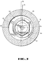
- FIG. 3 a cross sectional end view of the drill string 10 adjacent the joint illustrated in Fig. 2 is shown.
- the cross section through the drill string 10 is taken at a point slightly above the first body 44 so as to further illustrate the relationship of the valve 36 with the drill string 10.
- the first coordinate system 70 represents the radial centerpoint of the drill string 10 and, in particular, the second body 46 of the valve 36.
- the second coordinate system 72 represents the centerpoint of the rotor of the down-hole motor 22 and is offset slightly from the centerpoint of the drill string 10. As is conventional, proper operation of the down-hole motor 22 requires that it be offset from the longitudinal axis of the drill string 10.
- This offset in the down-hole motor 22 requires that the diameters of the first and second bodies 44, 46 be carefully selected to ensure sufficient overlap of the mating surfaces 40, 42.
- the outer diameter of the first longitudinal section 52 of the first body 44 should be greater than the inner diameter of the second longitudinal section 62 of the second body 46 by a distance at least as large as the offset.
- the diameter of the first longitudinal section 52 of the first body 44 should be less than the diameter of the first longitudinal section 60 of the second body 46 by a distance at least as large as the offset. This same relationship should be observed between the second longitudinal sections 54, 62 of the first and second bodies 44, 46.
- first and second bodies 44, 46 have been described herein as being generally or substantially coaxially arranged. However, as is apparent from Fig. 3, the longitudinal axes of the first and second bodies 44, 46 are, in fact, offset by a distance corresponding to the offset of the down-hole motor 22 from the drill string 10 longitudinal axis.
- coaxial has been used in a general sense only to describe the approximate relationship between the first and second bodies 44, 46.
- the axes of the first and second bodies 44, 46 can depart from precisely coaxial by a substantial distance without departing from the meaning of our use of the phrases "generally or substantially coaxial.”
Landscapes
- Engineering & Computer Science (AREA)
- Life Sciences & Earth Sciences (AREA)
- Mining & Mineral Resources (AREA)
- Geology (AREA)
- Physics & Mathematics (AREA)
- General Life Sciences & Earth Sciences (AREA)
- Environmental & Geological Engineering (AREA)
- Fluid Mechanics (AREA)
- Geochemistry & Mineralogy (AREA)
- Mechanical Engineering (AREA)
- Geophysics (AREA)
- Remote Sensing (AREA)
- Acoustics & Sound (AREA)
- Earth Drilling (AREA)
- Perforating, Stamping-Out Or Severing By Means Other Than Cutting (AREA)
- Spinning Or Twisting Of Yarns (AREA)
- Manufacture Of Motors, Generators (AREA)
- Adornments (AREA)
- Branch Pipes, Bends, And The Like (AREA)
- Re-Forming, After-Treatment, Cutting And Transporting Of Glass Products (AREA)
- Portable Nailing Machines And Staplers (AREA)
- Yarns And Mechanical Finishing Of Yarns Or Ropes (AREA)
- Knitting Machines (AREA)
Priority Applications (1)
| Application Number | Priority Date | Filing Date | Title |
|---|---|---|---|
| AT9191309761T ATE105603T1 (de) | 1990-10-26 | 1991-10-22 | Vorrichtung zur verhinderung der abtrennung eines bohrlochmotors von dem bohrstrang. |
Applications Claiming Priority (2)
| Application Number | Priority Date | Filing Date | Title |
|---|---|---|---|
| US07/604,783 US5165492A (en) | 1990-10-26 | 1990-10-26 | Apparatus for preventing separation of a down-hole motor from a drill string |
| US604783 | 1990-10-26 |
Publications (2)
| Publication Number | Publication Date |
|---|---|
| EP0482892A1 true EP0482892A1 (de) | 1992-04-29 |
| EP0482892B1 EP0482892B1 (de) | 1994-05-11 |
Family
ID=24421027
Family Applications (1)
| Application Number | Title | Priority Date | Filing Date |
|---|---|---|---|
| EP91309761A Expired - Lifetime EP0482892B1 (de) | 1990-10-26 | 1991-10-22 | Vorrichtung zur Verhinderung der Abtrennung eines Bohrlochmotors von dem Bohrstrang |
Country Status (12)
| Country | Link |
|---|---|
| US (1) | US5165492A (de) |
| EP (1) | EP0482892B1 (de) |
| JP (1) | JPH0693788A (de) |
| AT (1) | ATE105603T1 (de) |
| AU (1) | AU642775B2 (de) |
| CA (1) | CA2053683A1 (de) |
| DE (1) | DE69101963T2 (de) |
| DK (1) | DK0482892T3 (de) |
| ES (1) | ES2053287T3 (de) |
| FI (1) | FI95498C (de) |
| NO (1) | NO914178L (de) |
| TW (1) | TW205082B (de) |
Cited By (1)
| Publication number | Priority date | Publication date | Assignee | Title |
|---|---|---|---|---|
| EP3749827A4 (de) * | 2018-06-21 | 2021-11-24 | Halliburton Energy Services Inc. | Bohrkomponentenkuppler zur verstärkung |
Families Citing this family (12)
| Publication number | Priority date | Publication date | Assignee | Title |
|---|---|---|---|---|
| GB9823411D0 (en) * | 1998-10-26 | 1998-12-23 | Norske Stats Oljeselskap | Down hole motors and methods for their operation |
| US6145602A (en) * | 1999-03-05 | 2000-11-14 | Canadian Downhole Drill Systems Inc. | Downhole tool catcher and method |
| US6540020B1 (en) | 2002-06-17 | 2003-04-01 | Tomahawk Downhole, Llc | Motor by-pass valve |
| CA2439331C (en) * | 2003-09-02 | 2011-01-18 | William Ray Wenzel | Method of stabilizing a downhole drilling motor and a downhole drilling motor |
| US7063175B1 (en) | 2004-06-16 | 2006-06-20 | Scott Kerstetter | Method and apparatus for retaining a down-hole fluid motor and bit assembly |
| CN102007266B (zh) * | 2008-04-18 | 2014-09-10 | 国际壳牌研究有限公司 | 用于处理地下含烃地层的系统和方法 |
| CN103061685B (zh) * | 2013-01-08 | 2017-02-08 | 深圳市阿特拉能源技术有限公司 | 井底钻进工具及其防脱落自锁紧结构 |
| US9976349B2 (en) * | 2013-09-09 | 2018-05-22 | Weatherford Technology Holdings, Llc | Apparatus for preventing separation of downhole motor from drillstring |
| DE102013113752A1 (de) | 2013-12-10 | 2015-06-11 | Wilka Schließtechnik GmbH | Elektromechanischer Schließzylinder |
| CA2997210C (en) * | 2015-10-19 | 2020-03-10 | Halliburton Energy Services, Inc. | Rotor catch assembly |
| US11585162B2 (en) | 2017-11-29 | 2023-02-21 | Nabors Lux 2 Sarl | System and method for making a threaded connection |
| US11105154B1 (en) | 2020-06-09 | 2021-08-31 | Osado Innovations, LLC | Mud motor bearing and top sub rotor catch system |
Citations (3)
| Publication number | Priority date | Publication date | Assignee | Title |
|---|---|---|---|---|
| US1796611A (en) * | 1927-06-20 | 1931-03-17 | Gustavus A Montgomery | Unscrewing preventer |
| US3203713A (en) * | 1962-05-03 | 1965-08-31 | James H Pangburn | Auxiliary drill collar connection |
| US4823889A (en) * | 1987-08-21 | 1989-04-25 | Vsesojuzny Nauchno-Issledovatelsky Institut Burovoi Tekhniki | Downhole screw motor |
Family Cites Families (7)
| Publication number | Priority date | Publication date | Assignee | Title |
|---|---|---|---|---|
| US3191905A (en) * | 1962-10-12 | 1965-06-29 | Otis Eng Co | Gravity operated kelly foot valve |
| US3410355A (en) * | 1966-08-02 | 1968-11-12 | Smith Ind International Inc | Telescopic joint having means for signalling when the joint is extended |
| US3989114A (en) * | 1975-03-17 | 1976-11-02 | Smith International, Inc. | Circulation sub for in-hole hydraulic motors |
| US4187918A (en) * | 1978-06-12 | 1980-02-12 | Wallace Clark | Down-hole earth drilling motor capable of free circulation |
| FR2434922A1 (fr) * | 1978-08-28 | 1980-03-28 | Inst Francais Du Petrole | Dispositif inverseur du sens de circulation d'un fluide au niveau d'un outil de forage |
| US4632193A (en) * | 1979-07-06 | 1986-12-30 | Smith International, Inc. | In-hole motor with bit clutch and circulation sub |
| US4768598A (en) * | 1987-10-01 | 1988-09-06 | Baker Hughes Incorporated | Fluid pressure actuated bypass and pressure indicating relief valve |
-
1990
- 1990-10-26 US US07/604,783 patent/US5165492A/en not_active Expired - Lifetime
-
1991
- 1991-10-18 CA CA002053683A patent/CA2053683A1/en not_active Abandoned
- 1991-10-22 DK DK91309761.4T patent/DK0482892T3/da active
- 1991-10-22 EP EP91309761A patent/EP0482892B1/de not_active Expired - Lifetime
- 1991-10-22 AU AU86036/91A patent/AU642775B2/en not_active Ceased
- 1991-10-22 ES ES91309761T patent/ES2053287T3/es not_active Expired - Lifetime
- 1991-10-22 AT AT9191309761T patent/ATE105603T1/de not_active IP Right Cessation
- 1991-10-22 DE DE69101963T patent/DE69101963T2/de not_active Expired - Fee Related
- 1991-10-24 NO NO91914178A patent/NO914178L/no unknown
- 1991-10-25 FI FI915059A patent/FI95498C/fi not_active IP Right Cessation
- 1991-10-28 JP JP3307169A patent/JPH0693788A/ja active Pending
- 1991-11-04 TW TW080108660A patent/TW205082B/zh active
Patent Citations (3)
| Publication number | Priority date | Publication date | Assignee | Title |
|---|---|---|---|---|
| US1796611A (en) * | 1927-06-20 | 1931-03-17 | Gustavus A Montgomery | Unscrewing preventer |
| US3203713A (en) * | 1962-05-03 | 1965-08-31 | James H Pangburn | Auxiliary drill collar connection |
| US4823889A (en) * | 1987-08-21 | 1989-04-25 | Vsesojuzny Nauchno-Issledovatelsky Institut Burovoi Tekhniki | Downhole screw motor |
Cited By (1)
| Publication number | Priority date | Publication date | Assignee | Title |
|---|---|---|---|---|
| EP3749827A4 (de) * | 2018-06-21 | 2021-11-24 | Halliburton Energy Services Inc. | Bohrkomponentenkuppler zur verstärkung |
Also Published As
| Publication number | Publication date |
|---|---|
| ES2053287T3 (es) | 1994-07-16 |
| FI915059L (fi) | 1992-04-27 |
| FI95498C (fi) | 1996-02-12 |
| FI95498B (fi) | 1995-10-31 |
| DE69101963D1 (de) | 1994-06-16 |
| NO914178D0 (no) | 1991-10-24 |
| CA2053683A1 (en) | 1992-04-27 |
| ATE105603T1 (de) | 1994-05-15 |
| US5165492A (en) | 1992-11-24 |
| AU8603691A (en) | 1992-04-30 |
| DE69101963T2 (de) | 1994-08-18 |
| FI915059A0 (fi) | 1991-10-25 |
| EP0482892B1 (de) | 1994-05-11 |
| TW205082B (de) | 1993-05-01 |
| NO914178L (no) | 1992-04-27 |
| JPH0693788A (ja) | 1994-04-05 |
| DK0482892T3 (da) | 1994-09-26 |
| AU642775B2 (en) | 1993-10-28 |
Similar Documents
| Publication | Publication Date | Title |
|---|---|---|
| US5165492A (en) | Apparatus for preventing separation of a down-hole motor from a drill string | |
| US5996712A (en) | Mechanical locking swivel apparatus | |
| US5941323A (en) | Steerable directional drilling tool | |
| US9382760B2 (en) | Pulsing tool | |
| US5810100A (en) | Non-rotating stabilizer and centralizer for well drilling operations | |
| US10865612B2 (en) | Downhole pulsation system and method | |
| CA1285550C (en) | Core drilling tool for boreholes in rock | |
| CA3036840C (en) | Downhole tool system and method | |
| US4390171A (en) | Compression spring capsule | |
| US4884643A (en) | Downhole adjustable bent sub | |
| US4936397A (en) | Earth drilling apparatus with control valve | |
| US11280413B2 (en) | Choke valve having gate body with multiple metering segments | |
| WO2019009911A1 (en) | CONTROL VALVE OF STEERING ASSEMBLY | |
| WO2005080745A1 (en) | Drill pipe header | |
| US8051928B2 (en) | Downhole assembly and cutter assembly | |
| US12305481B2 (en) | Selectively activated friction reduction tool and method | |
| US11859459B2 (en) | Downhole tool | |
| US7063175B1 (en) | Method and apparatus for retaining a down-hole fluid motor and bit assembly | |
| US4290578A (en) | Failsafe cutoff valve for oil and gas wells | |
| US12221835B1 (en) | Downhole reamer with rotating sleeve | |
| BR112019017729A2 (pt) | aparelho de cortador rotativo, sistema de perfuração, e, método para reduzir um tamanho de objetos sólidos contidos em um fluido | |
| MXPA97008253A (en) | Adapter for sarta of rods of perforac |
Legal Events
| Date | Code | Title | Description |
|---|---|---|---|
| PUAI | Public reference made under article 153(3) epc to a published international application that has entered the european phase |
Free format text: ORIGINAL CODE: 0009012 |
|
| AK | Designated contracting states |
Kind code of ref document: A1 Designated state(s): AT BE CH DE DK ES FR GB GR IT LI LU NL SE |
|
| 17P | Request for examination filed |
Effective date: 19920706 |
|
| 17Q | First examination report despatched |
Effective date: 19921106 |
|
| GRAA | (expected) grant |
Free format text: ORIGINAL CODE: 0009210 |
|
| RAP1 | Party data changed (applicant data changed or rights of an application transferred) |
Owner name: DAILEY PETROLEUM SERVICES CORP. |
|
| AK | Designated contracting states |
Kind code of ref document: B1 Designated state(s): AT BE CH DE DK ES FR GB GR IT LI LU NL SE |
|
| REF | Corresponds to: |
Ref document number: 105603 Country of ref document: AT Date of ref document: 19940515 Kind code of ref document: T |
|
| ITF | It: translation for a ep patent filed | ||
| REF | Corresponds to: |
Ref document number: 69101963 Country of ref document: DE Date of ref document: 19940616 |
|
| ET | Fr: translation filed | ||
| REG | Reference to a national code |
Ref country code: ES Ref legal event code: FG2A Ref document number: 2053287 Country of ref document: ES Kind code of ref document: T3 |
|
| REG | Reference to a national code |
Ref country code: GR Ref legal event code: FG4A Free format text: 3011926 |
|
| REG | Reference to a national code |
Ref country code: DK Ref legal event code: T3 |
|
| EAL | Se: european patent in force in sweden |
Ref document number: 91309761.4 |
|
| PLBE | No opposition filed within time limit |
Free format text: ORIGINAL CODE: 0009261 |
|
| STAA | Information on the status of an ep patent application or granted ep patent |
Free format text: STATUS: NO OPPOSITION FILED WITHIN TIME LIMIT |
|
| 26N | No opposition filed | ||
| PGFP | Annual fee paid to national office [announced via postgrant information from national office to epo] |
Ref country code: FR Payment date: 19971009 Year of fee payment: 7 |
|
| PGFP | Annual fee paid to national office [announced via postgrant information from national office to epo] |
Ref country code: GB Payment date: 19971013 Year of fee payment: 7 |
|
| PGFP | Annual fee paid to national office [announced via postgrant information from national office to epo] |
Ref country code: AT Payment date: 19971014 Year of fee payment: 7 |
|
| PGFP | Annual fee paid to national office [announced via postgrant information from national office to epo] |
Ref country code: DK Payment date: 19971016 Year of fee payment: 7 |
|
| PGFP | Annual fee paid to national office [announced via postgrant information from national office to epo] |
Ref country code: GR Payment date: 19971021 Year of fee payment: 7 |
|
| PGFP | Annual fee paid to national office [announced via postgrant information from national office to epo] |
Ref country code: ES Payment date: 19971022 Year of fee payment: 7 |
|
| PGFP | Annual fee paid to national office [announced via postgrant information from national office to epo] |
Ref country code: SE Payment date: 19971029 Year of fee payment: 7 Ref country code: NL Payment date: 19971029 Year of fee payment: 7 |
|
| PGFP | Annual fee paid to national office [announced via postgrant information from national office to epo] |
Ref country code: LU Payment date: 19971030 Year of fee payment: 7 |
|
| PGFP | Annual fee paid to national office [announced via postgrant information from national office to epo] |
Ref country code: DE Payment date: 19971031 Year of fee payment: 7 |
|
| PGFP | Annual fee paid to national office [announced via postgrant information from national office to epo] |
Ref country code: CH Payment date: 19971106 Year of fee payment: 7 |
|
| PGFP | Annual fee paid to national office [announced via postgrant information from national office to epo] |
Ref country code: BE Payment date: 19971211 Year of fee payment: 7 |
|
| REG | Reference to a national code |
Ref country code: CH Ref legal event code: PFA Free format text: DAILEY PETROLEUM SERVICES CORP. TRANSFER- DAILEY INTERNATIONAL INC. |
|
| REG | Reference to a national code |
Ref country code: FR Ref legal event code: CD |
|
| NLT1 | Nl: modifications of names registered in virtue of documents presented to the patent office pursuant to art. 16 a, paragraph 1 |
Owner name: DAILEY INTERNATIONAL INC. |
|
| REG | Reference to a national code |
Ref country code: ES Ref legal event code: PC2A |
|
| PG25 | Lapsed in a contracting state [announced via postgrant information from national office to epo] |
Ref country code: LU Free format text: LAPSE BECAUSE OF NON-PAYMENT OF DUE FEES Effective date: 19981022 Ref country code: GB Free format text: LAPSE BECAUSE OF NON-PAYMENT OF DUE FEES Effective date: 19981022 Ref country code: DK Free format text: LAPSE BECAUSE OF NON-PAYMENT OF DUE FEES Effective date: 19981022 Ref country code: AT Free format text: LAPSE BECAUSE OF NON-PAYMENT OF DUE FEES Effective date: 19981022 |
|
| PG25 | Lapsed in a contracting state [announced via postgrant information from national office to epo] |
Ref country code: SE Free format text: LAPSE BECAUSE OF NON-PAYMENT OF DUE FEES Effective date: 19981023 Ref country code: ES Free format text: LAPSE BECAUSE OF NON-PAYMENT OF DUE FEES Effective date: 19981023 |
|
| PG25 | Lapsed in a contracting state [announced via postgrant information from national office to epo] |
Ref country code: LI Free format text: LAPSE BECAUSE OF NON-PAYMENT OF DUE FEES Effective date: 19981031 Ref country code: GR Free format text: LAPSE BECAUSE OF NON-PAYMENT OF DUE FEES Effective date: 19981031 Ref country code: CH Free format text: LAPSE BECAUSE OF NON-PAYMENT OF DUE FEES Effective date: 19981031 Ref country code: BE Free format text: LAPSE BECAUSE OF NON-PAYMENT OF DUE FEES Effective date: 19981031 |
|
| BERE | Be: lapsed |
Owner name: DAILEY INTERNATIONAL INC. Effective date: 19981031 |
|
| PG25 | Lapsed in a contracting state [announced via postgrant information from national office to epo] |
Ref country code: NL Free format text: LAPSE BECAUSE OF NON-PAYMENT OF DUE FEES Effective date: 19990501 |
|
| GBPC | Gb: european patent ceased through non-payment of renewal fee |
Effective date: 19981022 |
|
| REG | Reference to a national code |
Ref country code: CH Ref legal event code: PL |
|
| EUG | Se: european patent has lapsed |
Ref document number: 91309761.4 |
|
| PG25 | Lapsed in a contracting state [announced via postgrant information from national office to epo] |
Ref country code: FR Free format text: LAPSE BECAUSE OF NON-PAYMENT OF DUE FEES Effective date: 19990630 |
|
| NLV4 | Nl: lapsed or anulled due to non-payment of the annual fee |
Effective date: 19990501 |
|
| REG | Reference to a national code |
Ref country code: FR Ref legal event code: ST |
|
| PG25 | Lapsed in a contracting state [announced via postgrant information from national office to epo] |
Ref country code: DE Free format text: LAPSE BECAUSE OF NON-PAYMENT OF DUE FEES Effective date: 19990803 |
|
| REG | Reference to a national code |
Ref country code: DK Ref legal event code: EBP |
|
| REG | Reference to a national code |
Ref country code: ES Ref legal event code: FD2A Effective date: 19991113 |
|
| PG25 | Lapsed in a contracting state [announced via postgrant information from national office to epo] |
Ref country code: IT Free format text: LAPSE BECAUSE OF NON-PAYMENT OF DUE FEES Effective date: 20051022 |