EP0483021B1 - Obturateur verrouillable pour coffret électrique - Google Patents
Obturateur verrouillable pour coffret électrique Download PDFInfo
- Publication number
- EP0483021B1 EP0483021B1 EP91420320A EP91420320A EP0483021B1 EP 0483021 B1 EP0483021 B1 EP 0483021B1 EP 91420320 A EP91420320 A EP 91420320A EP 91420320 A EP91420320 A EP 91420320A EP 0483021 B1 EP0483021 B1 EP 0483021B1
- Authority
- EP
- European Patent Office
- Prior art keywords
- branch
- blanking plate
- plate
- opening
- plate according
- Prior art date
- Legal status (The legal status is an assumption and is not a legal conclusion. Google has not performed a legal analysis and makes no representation as to the accuracy of the status listed.)
- Expired - Lifetime
Links
- 238000006243 chemical reaction Methods 0.000 claims description 3
- 238000001125 extrusion Methods 0.000 claims description 3
- 239000000463 material Substances 0.000 claims description 2
- 238000009434 installation Methods 0.000 description 3
- 238000006073 displacement reaction Methods 0.000 description 1
- 230000000694 effects Effects 0.000 description 1
- 230000005489 elastic deformation Effects 0.000 description 1
Images


Classifications
-
- H—ELECTRICITY
- H02—GENERATION; CONVERSION OR DISTRIBUTION OF ELECTRIC POWER
- H02G—INSTALLATION OF ELECTRIC CABLES OR LINES, OR OF COMBINED OPTICAL AND ELECTRIC CABLES OR LINES
- H02G3/00—Installations of electric cables or lines or protective tubing therefor in or on buildings, equivalent structures or vehicles
- H02G3/02—Details
- H02G3/08—Distribution boxes; Connection or junction boxes
- H02G3/14—Fastening of cover or lid to box
-
- H—ELECTRICITY
- H02—GENERATION; CONVERSION OR DISTRIBUTION OF ELECTRIC POWER
- H02B—BOARDS, SUBSTATIONS OR SWITCHING ARRANGEMENTS FOR THE SUPPLY OR DISTRIBUTION OF ELECTRIC POWER
- H02B1/00—Frameworks, boards, panels, desks, casings; Details of substations or switching arrangements
- H02B1/015—Boards, panels, desks; Parts thereof or accessories therefor
- H02B1/06—Boards, panels, desks; Parts thereof or accessories therefor having associated enclosures, e.g. for preventing access to live parts
-
- H—ELECTRICITY
- H02—GENERATION; CONVERSION OR DISTRIBUTION OF ELECTRIC POWER
- H02G—INSTALLATION OF ELECTRIC CABLES OR LINES, OR OF COMBINED OPTICAL AND ELECTRIC CABLES OR LINES
- H02G3/00—Installations of electric cables or lines or protective tubing therefor in or on buildings, equivalent structures or vehicles
- H02G3/02—Details
- H02G3/04—Protective tubing or conduits, e.g. cable ladders or cable troughs
- H02G3/0406—Details thereof
- H02G3/0418—Covers or lids; Their fastenings
-
- H—ELECTRICITY
- H02—GENERATION; CONVERSION OR DISTRIBUTION OF ELECTRIC POWER
- H02G—INSTALLATION OF ELECTRIC CABLES OR LINES, OR OF COMBINED OPTICAL AND ELECTRIC CABLES OR LINES
- H02G3/00—Installations of electric cables or lines or protective tubing therefor in or on buildings, equivalent structures or vehicles
- H02G3/02—Details
- H02G3/04—Protective tubing or conduits, e.g. cable ladders or cable troughs
- H02G3/0431—Wall trunking
-
- H—ELECTRICITY
- H02—GENERATION; CONVERSION OR DISTRIBUTION OF ELECTRIC POWER
- H02B—BOARDS, SUBSTATIONS OR SWITCHING ARRANGEMENTS FOR THE SUPPLY OR DISTRIBUTION OF ELECTRIC POWER
- H02B1/00—Frameworks, boards, panels, desks, casings; Details of substations or switching arrangements
- H02B1/015—Boards, panels, desks; Parts thereof or accessories therefor
- H02B2001/0155—Removable shutters for non-used openings
Definitions
- the invention relates to a removable shutter capable of closing a rectangular opening, formed in a faceplate or front face of a housing for housing electrical equipment with modular housings, said shutter comprising a plastic body provided with means for fixing having a first deformable branch arranged in positioning clamp intended to be engaged overlapping on the lower edge of the opening.
- the fixing means comprise a second elastic branch arranged opposite the positioning clip to ensure clipping of the shutter on the upper edge of the opening of the faceplate.
- the effect of clipping is obtained by a pressure exerted on the shutter from the front, and it is essential to fix from the rear an additional locking piece to obtain a total condemnation when the faceplate is secured to the front face of the box.
- the object of the invention is to provide a one-piece shutter with integrated locking.
- the shutter according to the invention is characterized in that the body is shaped as a profile obtained by extrusion, and comprises a rigid plate, equipped on its rear face with first and second longitudinal ribs for supporting the plate against the lower and upper edges of the opening, and of a second branch pivotally movable between a closed locking position and an open unlocking position, said second branch being provided with a snap hook cooperating in the closed position with a retaining rim secured to the rear face of the plate.
- the hook is snapped onto the flange behind the cover plate, so that it is inaccessible after installation in place of the faceplate, causing a condemnation of the unoccupied area of the opening.
- the removal of the shutter requires a preliminary disassembly of the faceplate before actuating the second branch towards the open unlocking position.
- the hook retaining edge is located between the second support rib and the fixing base of the second branch.
- the latching area is distant from the upper edge of the opening.
- the second branch is longer than the first branch, and is connected to the corresponding base by a hinge allowing longitudinal folding in the direction of the pivoting movement.
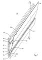
- a removable shutter 10 can be mounted on the two upper and lower edges of a rectangular opening 12, formed in a faceplate 14 or front face of a housing (not shown) housing electrical equipment with modular housings.
- the opening 12 extends over almost the entire width of the box, and allows the projecting of the front part of the boxes for access to the control levers after removal of the shutter 10.
- the installation the shutter 10 operates exclusively in the area devoid of apparatus, so as to block the unoccupied part of the opening 12.
- the shutter 10 is constituted by a profiled body made of plastic material produced by extrusion, and comprising a rigid plate 16 of rectangular shape, having a substantially flat front face 18, which is visible in the position mounted in the opening 12 (FIG. 3) .
- the rear face 20 of the shutter 10 is equipped with two branches 22, 24 of different lengths, extending respectively from two fixing bases 26, 28, being bent in opposite directions from one another.
- the shortest first branch 22 is deformable by elasticity, and is directed downwards by cooperating with the rigid lower part of the plate 16 to constitute a clamp 30 for positioning in the shape of an inverted U, capable of being engaged overlapping on the lower edge of the opening 12.
- a first support rib 32 projecting from the rear face 20, extending along the longitudinal direction of the profile.
- the upper end of the rear face 20 is provided with a second support rib 36, parallel to the opposite first rib 32.
- the spacing between the outer faces of the two ribs 32, 36 corresponds substantially to the distance between the upper and lower edges of the opening 12.
- a retaining rim 38 intended to cooperate with a snap hook 40 when the branch 24 is actuated towards the closed position.
- the hook 40 is located in the middle zone of the second branch 24, and its attachment to the rim 38 is facilitated by the elasticity of the second branch 24, which has a thickness less than that of the plate 16.
- the ends of the two elastic branches 22, 24 exceed the respective opposite edges of the rigid plate 16.
- the juxtaposition of the two bases 26, 28 on the rear face 20 delimits a longitudinal groove 42 for separating the two branches 22, 24.
- the end 44 of the second branch 24 acts as a gripping lever, intended to move the movable branch 24 towards the open unlocking position.
- the profile of the shutter 10 may include precut lines (not shown) staggered at regularized regular intervals along the longitudinal direction. The splitting or sawing of these lines makes it possible to obtain one-piece shutters of predetermined lengths, adaptable to the unoccupied part of the opening 12.
- the shutter 10 can be completely embedded in a window 46 (FIG. 3) of the front plate 14, said window having a dimension slightly greater than that of the adjacent opening 12. Maintaining the shutter 10 in the window 46 results from the hooking of the hook 40 on the rim 38 after the second branch 24 has been brought together.
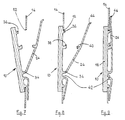
- FIGS. 4 to 6 The installation of the shutter 10 in the opening 12 is illustrated in FIGS. 4 to 6, using a flat faceplate 14:
- the positioning clamp 30 is mounted overlapping on the lower edge of the opening 12, with support of the first rib 32 on an edge of the edge ( Figure 4).
- the pivoting of the plate 16 in the clockwise direction then ensures the abutment of the upper part against the faceplate 14 ( Figure 5).
- the plate 16 is then projecting from the faceplate 14, and it suffices to snap the hook 40 onto the flange 38 to permanently fix the shutter 10 in the opening 12 (FIG. 6).
- the thickness of the plastron 14 is less than that of the plastron of FIGS. 4 to 6, and there is a more pronounced elastic deformation of the second branch 24 to ensure that the hook 40 is snapped onto the ledge 38.
- the removal of the shutter 10 requires the preliminary disassembly of the faceplate 14 in order to access the end 44 of the gripping lever authorizing the displacement of the second branch 24 towards the open position for unlocking the hook 40.
Landscapes
- Engineering & Computer Science (AREA)
- Architecture (AREA)
- Civil Engineering (AREA)
- Structural Engineering (AREA)
- Power Engineering (AREA)
- Operating, Guiding And Securing Of Roll- Type Closing Members (AREA)
- Details Of Indoor Wiring (AREA)
- Casings For Electric Apparatus (AREA)
- Connection Of Plates (AREA)
Applications Claiming Priority (2)
| Application Number | Priority Date | Filing Date | Title |
|---|---|---|---|
| FR9012266 | 1990-09-28 | ||
| FR9012266A FR2667454B1 (fr) | 1990-09-28 | 1990-09-28 | Obturateur verrouillage pour coffret electrique. |
Publications (2)
| Publication Number | Publication Date |
|---|---|
| EP0483021A1 EP0483021A1 (fr) | 1992-04-29 |
| EP0483021B1 true EP0483021B1 (fr) | 1995-01-18 |
Family
ID=9400949
Family Applications (1)
| Application Number | Title | Priority Date | Filing Date |
|---|---|---|---|
| EP91420320A Expired - Lifetime EP0483021B1 (fr) | 1990-09-28 | 1991-09-12 | Obturateur verrouillable pour coffret électrique |
Country Status (5)
| Country | Link |
|---|---|
| EP (1) | EP0483021B1 (pt) |
| DE (1) | DE69106837T2 (pt) |
| ES (1) | ES2069865T3 (pt) |
| FR (1) | FR2667454B1 (pt) |
| PT (1) | PT99080A (pt) |
Families Citing this family (5)
| Publication number | Priority date | Publication date | Assignee | Title |
|---|---|---|---|---|
| FR2728734B1 (fr) * | 1994-12-22 | 1997-01-24 | Schneider Electric Sa | Cadre profile a poser sur une enveloppe, notamment pour appareils electriques |
| DE19809584C2 (de) * | 1998-03-06 | 2000-07-13 | Loh Kg Ritto Werk | Türsprechanlage |
| FR2811151B1 (fr) * | 2000-06-29 | 2002-10-04 | Legrand Sa | Obturateur pour fenetre de plastron, notamment pour armoire electrique |
| DE102010033319A1 (de) * | 2010-08-04 | 2012-02-09 | Protektorwerk Florenz Maisch Gmbh & Co. Kg | Schrankprofil, insbesondere Schaltschrankprofil und Schrank, insbesondere Schaltschrank |
| DE102019134863B4 (de) * | 2019-12-18 | 2022-09-01 | Hager Electro Gmbh & Co. Kg | Abdeckungsanordnung für einen Verteilerschrank und Verteilerschrank umfassend eine solche Abdeckungsanordnung |
Family Cites Families (4)
| Publication number | Priority date | Publication date | Assignee | Title |
|---|---|---|---|---|
| US3677434A (en) * | 1970-05-18 | 1972-07-18 | Fred S Boyer | Locking devices |
| FR2413809A1 (fr) * | 1977-12-27 | 1979-07-27 | Hager Electro | Perfectionnements aux obturateurs pour coffrets de distribution a appareillage de dimensions standardisees |
| US4687164A (en) * | 1983-12-01 | 1987-08-18 | Mechanical Products, Inc. | Snap-in bushing |
| DE8808049U1 (de) * | 1988-06-23 | 1988-08-25 | Gebr. Vedder GmbH, 5885 Schalksmühle | Abdeckrahmen für Einbau-Elektroinstallationsgeräte |
-
1990
- 1990-09-28 FR FR9012266A patent/FR2667454B1/fr not_active Expired - Fee Related
-
1991
- 1991-09-12 ES ES91420320T patent/ES2069865T3/es not_active Expired - Lifetime
- 1991-09-12 EP EP91420320A patent/EP0483021B1/fr not_active Expired - Lifetime
- 1991-09-12 DE DE69106837T patent/DE69106837T2/de not_active Expired - Fee Related
- 1991-09-26 PT PT99080A patent/PT99080A/pt not_active Application Discontinuation
Also Published As
| Publication number | Publication date |
|---|---|
| EP0483021A1 (fr) | 1992-04-29 |
| ES2069865T3 (es) | 1995-05-16 |
| PT99080A (pt) | 1993-10-29 |
| DE69106837D1 (de) | 1995-03-02 |
| FR2667454A1 (fr) | 1992-04-03 |
| DE69106837T2 (de) | 1995-08-17 |
| FR2667454B1 (fr) | 1992-11-06 |
Similar Documents
| Publication | Publication Date | Title |
|---|---|---|
| EP1229624B1 (fr) | Accessoire pour goulotte et ensemble comprenant un tel accessoire et une goulotte dont le socle est spécialement adapté audit accessoire | |
| EP0470010B1 (fr) | Coffret étanche d'appareillage électrique | |
| EP3138167B1 (fr) | Appareillage électrique a assemblage sécurisé | |
| EP0980948B1 (fr) | Dispositif de montage de commande d'ouverture de porte de véhicule | |
| EP0483021A1 (fr) | Obturateur verrouillable pour coffret électrique | |
| EP0628695B1 (fr) | Dispositif de fermeture des extrémités latérales de coffres de volet roulant | |
| EP1071183B1 (fr) | Support d'appareillage électrique à rapporter sur une goulotte | |
| EP2458700B1 (fr) | Appareillage électrique à support d'appareillage basculant | |
| EP2146363B1 (fr) | Appareil électrique modulaire comprenant un capot protège-étiquette et une tirette support d'étiquette | |
| FR3013914A1 (fr) | Support d'appareillage comportant un accessoire de griffage pour sa fixation a une boite murale, accessoire de griffage, ensemble de griffage et appareillage electrique associes | |
| EP1030015B1 (fr) | Ferrure de verrouillage du type crémone ou analogue | |
| EP3159989B1 (fr) | Boîte électrique à encastrer dans une paroi | |
| EP0673806B1 (fr) | Dispositif de montage d'un pare-chocs sur la carrosserie d'un vehicule automobile. | |
| EP1139537B1 (fr) | Boîtier pour appareillage à disposer le long d'une goulotte, notamment pour appareillage électrique | |
| EP1137897B1 (fr) | Coffret de raccordement et de protection pour candelabre | |
| EP1164676A1 (fr) | Dispositif de montage d'un appareil électrique sur un conduit de câblage | |
| FR3105561A1 (fr) | Boîte électrique en deux parties | |
| FR2833772A1 (fr) | Accessoire d'immobilisation d'un appareillage electrique a clipsage direct dans un socle de goulotte | |
| EP1211773B1 (fr) | Support pour appareillage, en particulier pour appareillage électrique, à rapporter sur le socle d'une goulotte | |
| EP1372232A1 (fr) | Boítier électrique avec verrou articulé | |
| EP2320532B1 (fr) | Dispositif de montage d'un montant de châssis sur le fond d'un coffret électrique et coffret électrique comprenant un tel dispositif | |
| EP2341589B1 (fr) | Dispositif de montage d'un montant de châssis sur le fond d'un coffret électrique et coffret électrique comprenant un tel dispositif | |
| EP1191657B1 (fr) | Dispositif de fixation d'une goulotte sur un support décalé par rapport à un mur | |
| EP4023830B1 (fr) | Systeme de verrouillage de clip pour dalle | |
| EP1616735A2 (fr) | Dispositif de protection d'un passage d'air d'une boîte à eau de véhicule automobile, et boîte à eau correspondante |
Legal Events
| Date | Code | Title | Description |
|---|---|---|---|
| PUAI | Public reference made under article 153(3) epc to a published international application that has entered the european phase |
Free format text: ORIGINAL CODE: 0009012 |
|
| AK | Designated contracting states |
Kind code of ref document: A1 Designated state(s): BE CH DE ES GB IT LI SE |
|
| 17P | Request for examination filed |
Effective date: 19921015 |
|
| 17Q | First examination report despatched |
Effective date: 19940406 |
|
| GRAA | (expected) grant |
Free format text: ORIGINAL CODE: 0009210 |
|
| AK | Designated contracting states |
Kind code of ref document: B1 Designated state(s): BE CH DE ES GB IT LI SE |
|
| PG25 | Lapsed in a contracting state [announced via postgrant information from national office to epo] |
Ref country code: GB Effective date: 19950118 |
|
| REF | Corresponds to: |
Ref document number: 69106837 Country of ref document: DE Date of ref document: 19950302 |
|
| ITF | It: translation for a ep patent filed | ||
| PG25 | Lapsed in a contracting state [announced via postgrant information from national office to epo] |
Ref country code: SE Effective date: 19950418 |
|
| REG | Reference to a national code |
Ref country code: ES Ref legal event code: FG2A Ref document number: 2069865 Country of ref document: ES Kind code of ref document: T3 |
|
| GBV | Gb: ep patent (uk) treated as always having been void in accordance with gb section 77(7)/1977 [no translation filed] |
Effective date: 19950118 |
|
| PG25 | Lapsed in a contracting state [announced via postgrant information from national office to epo] |
Ref country code: LI Effective date: 19950930 Ref country code: CH Effective date: 19950930 |
|
| PLBE | No opposition filed within time limit |
Free format text: ORIGINAL CODE: 0009261 |
|
| STAA | Information on the status of an ep patent application or granted ep patent |
Free format text: STATUS: NO OPPOSITION FILED WITHIN TIME LIMIT |
|
| 26N | No opposition filed | ||
| REG | Reference to a national code |
Ref country code: CH Ref legal event code: PL |
|
| PGFP | Annual fee paid to national office [announced via postgrant information from national office to epo] |
Ref country code: BE Payment date: 19961118 Year of fee payment: 6 |
|
| PG25 | Lapsed in a contracting state [announced via postgrant information from national office to epo] |
Ref country code: BE Free format text: LAPSE BECAUSE OF NON-PAYMENT OF DUE FEES Effective date: 19970930 |
|
| BERE | Be: lapsed |
Owner name: MERLIN GERIN Effective date: 19970930 |
|
| PGFP | Annual fee paid to national office [announced via postgrant information from national office to epo] |
Ref country code: DE Payment date: 19990902 Year of fee payment: 9 |
|
| PGFP | Annual fee paid to national office [announced via postgrant information from national office to epo] |
Ref country code: ES Payment date: 19990920 Year of fee payment: 9 |
|
| PG25 | Lapsed in a contracting state [announced via postgrant information from national office to epo] |
Ref country code: ES Free format text: LAPSE BECAUSE OF NON-PAYMENT OF DUE FEES Effective date: 20000913 |
|
| PG25 | Lapsed in a contracting state [announced via postgrant information from national office to epo] |
Ref country code: DE Free format text: LAPSE BECAUSE OF NON-PAYMENT OF DUE FEES Effective date: 20010601 |
|
| REG | Reference to a national code |
Ref country code: ES Ref legal event code: FD2A Effective date: 20011011 |
|
| PG25 | Lapsed in a contracting state [announced via postgrant information from national office to epo] |
Ref country code: IT Free format text: LAPSE BECAUSE OF NON-PAYMENT OF DUE FEES;WARNING: LAPSES OF ITALIAN PATENTS WITH EFFECTIVE DATE BEFORE 2007 MAY HAVE OCCURRED AT ANY TIME BEFORE 2007. THE CORRECT EFFECTIVE DATE MAY BE DIFFERENT FROM THE ONE RECORDED. Effective date: 20050912 |