EP0483030A1 - Gepäckanhänger, umwandelbar in ein Boot - Google Patents
Gepäckanhänger, umwandelbar in ein Boot Download PDFInfo
- Publication number
- EP0483030A1 EP0483030A1 EP91420377A EP91420377A EP0483030A1 EP 0483030 A1 EP0483030 A1 EP 0483030A1 EP 91420377 A EP91420377 A EP 91420377A EP 91420377 A EP91420377 A EP 91420377A EP 0483030 A1 EP0483030 A1 EP 0483030A1
- Authority
- EP
- European Patent Office
- Prior art keywords
- cover
- trailer according
- trailer
- boat
- fixed
- Prior art date
- Legal status (The legal status is an assumption and is not a legal conclusion. Google has not performed a legal analysis and makes no representation as to the accuracy of the status listed.)
- Granted
Links
Images


Classifications
-
- B—PERFORMING OPERATIONS; TRANSPORTING
- B63—SHIPS OR OTHER WATERBORNE VESSELS; RELATED EQUIPMENT
- B63C—LAUNCHING, HAULING-OUT, OR DRY-DOCKING OF VESSELS; LIFE-SAVING IN WATER; EQUIPMENT FOR DWELLING OR WORKING UNDER WATER; MEANS FOR SALVAGING OR SEARCHING FOR UNDERWATER OBJECTS
- B63C13/00—Equipment forming part of or attachable to vessels facilitating transport over land
-
- B—PERFORMING OPERATIONS; TRANSPORTING
- B60—VEHICLES IN GENERAL
- B60R—VEHICLES, VEHICLE FITTINGS, OR VEHICLE PARTS, NOT OTHERWISE PROVIDED FOR
- B60R9/00—Supplementary fittings on vehicle exterior for carrying loads, e.g. luggage, sports gear or the like
- B60R9/04—Carriers associated with vehicle roof
- B60R9/055—Enclosure-type carriers, e.g. containers, boxes
-
- B—PERFORMING OPERATIONS; TRANSPORTING
- B63—SHIPS OR OTHER WATERBORNE VESSELS; RELATED EQUIPMENT
- B63B—SHIPS OR OTHER WATERBORNE VESSELS; EQUIPMENT FOR SHIPPING
- B63B7/00—Collapsible, foldable, inflatable or like vessels
- B63B7/02—Collapsible, foldable, inflatable or like vessels comprising only rigid parts
- B63B7/04—Collapsible, foldable, inflatable or like vessels comprising only rigid parts sectionalised
Definitions
- the present invention relates to a baggage trailer convertible into a boat, comprising a box and a cover adaptable on it for its closure, which are shaped so that they can be assembled in the extension of one another to constitute the hull of a boat.
- the body and the cover are generally articulated to each other by a hinge connecting the upper edge of their front, rear or side walls, and can be assembled in the extension of one another by means of appropriate hanging.
- These hooking members can be constituted either by bolts, latches or quick couplers, which pass through their rear walls or are fixed at their bottom near said rear walls, or by locking pins passing through bores coming in coaxial alignment in this position of the cover and the body, these bores being formed in complementary projections which comprise said rear faces.
- hooking members by their position close to the hinge axis of the body and the cover, can be subjected to significant tearing forces when the waves lift the ends of the boat, which can lead to their rupture or tearing of the walls of the boat. This can all the more occur as these efforts are exerted punctually and that, for the sake of lightness, said walls have only relative strength. Thus, significant waterways can be generated in the boat.
- hooking members in any case, have the drawback of needing to pierce the walls of the box and the cover in order to be able to be fixed and, therefore, involve the realization of a suitable seal.
- the boats thus obtained have the drawback of having quite relative stability and a generally narrow gunwale which is not very comfortable to sit on.
- the present invention aims to remedy these drawbacks.
- the trailer it concerns comprises at least one longitudinal beam constituted by at least two telescopic elements, the outer one of which is fixed to the outer face of a wall either of the body or of the cover, and of which at least one of those inside is intended, during its movement, to be engaged in a housing adjusted to its dimensions respectively provided either in the cover or in the box.
- This or these beams make it possible to perfectly ensure the assembly of the body and the cover in their position making it possible to constitute the boat and to perfectly stiffen the boat thus obtained, this assembly being, moreover, simple and quick to produce.
- the trailer comprises two lateral beams, the external elements of which are fixed to returns formed by the upper lateral edges of the body and the sliding internal elements of which are intended to be engaged in delimited chutes by similar returns formed by the opening side edges of the cover.
- These returns participate in the longitudinal rigidity of the boat and their upper faces constitute surfaces on which one can sit. They give it a secure appearance and make it possible to conceal the passage of electric wires, for example night lights.
- the beams also constitute elements of lateral stabilization and buoyancy insofar as their internal element is closed or filled with low density material, such as expanded polyurethane foam. Otherwise, these elements serve as storage for various accessories.
- the cover is advantageously provided so as to be able to be adapted on a car gallery. Thanks to him, the car maintains an aerodynamic profile despite the transport of luggage on the roof and the chutes it includes allow the easy transport of elongated objects, such as skis, fishing rods or other.
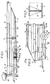
- FIG. 2 represents a trailer 1 which can be coupled to a vehicle thanks to its drawbar 2.
- the trailer 1 comprises a box 3 which can notably contain luggage and a cover 4 for closing it provided with a handle 5.
- the cover 4 is hinged to the upper rear edge of the body 3 by a hinge 6 allowing it to pivot relative to the latter over at least 180 degrees as well as its disassembly from it.
- the rear lights as well as the number plate of the trailer 1 are embedded in the wall of the body 3 so that this wall has a flat and smooth surface.
- the rear wall of the cover 4 also has a flat and smooth surface, except that it includes buffers 7 made of deformable material.
- the cover 4 the front part of which is profiled so as to be hydrodynamic, comes in the extension of the body 3 in the 180 ° pivoted position to form with it, in a particularly simple manner , easy and quick, the hull of a boat 8.
- the rear faces of the cover 4 and of the body 3 may have a complementary profile allowing them to be embedded in this position.
- Stops 17 and 18, respectively provided by the body 3 and the cover 4, are provided to limit the sliding of the elements 13b.
- the return 16 is accentuated towards the front of the boat, so that the cross section of the chute 15 decreases in order to jam the element 13b at the end of the deployed stroke thereof.
- the latter is also filled with expanded polyurethane foam 37, so as to constitute a buoyancy reserve.
- the horizontal walls 14a and 16a of the returns 14 and 16 constitute surfaces on which one can sit and give the boat a secure appearance.
- the front wall of the body 3 forms a chair 19 on which a so-called "outboard” motor 20 can be mounted.
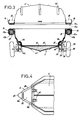
- Figure 4 shows that the drawbar 2 has a general U-shape whose central part 2a, which carries the coupling hook on a plate 21 and whose branches 2b, which are fixed to the side walls of the body 3, delimit between they, as well as with the front face of the body 3, an opening 22 whose dimensions allow the propeller and the motor shaft 20 to pass through it.
- the drawbar 2 thus forms a protective bumper for the latter.
- each free end of the branches 2b carries two plates lateral 25 fixed on it, provided with a pin 26 projecting perpendicular towards the outside around which is mounted a pivoting arm 27 constituted by an angle, this arm 27 carrying at one end the wheel 28 on a spindle 29 and at the other end an engaged axis 30, as well as an axis 31 which is parallel to it carried by the plates 25, inside a ring 32 of elastic material.
- Each branch 2b plays the role of a torsion bar and each elastic ring 32 that of a shock absorber of the movements of the arm 27.
- the shock absorbing system of the trailer is thus constituted in a very simple manner and the wheels 28 which remain stationary during the use of the boat participate in the buoyancy of the latter.
- FIG. 3 shows that the body 3 has a floor 35 attached at its bottom, this floor and this bottom defining between them a space filled with foam 36 of expanded polyurethane foam with closed cells whose volume increases at the rear of the boat, so as to compensate for the weight of the engine 20 in the event of a waterway in order to maintain the trim of the boat 8.
- the cover 4 and the box 3 comprise a plurality of stiffening ribs 40 molded with them. All the ribs 40 which they comprise have not been shown for the sake of clarity of the figures, and in particular in FIG. 3 of the stiffening members of the body 3.
- Figures 6 and 7 show, from different angles, an attachable baggage trailer 2, according to a second embodiment. Elements identical or similar to those previously described and which are found in this second embodiment are designated by the same references.
- box 3-cover assembly 4 can be detached from the chassis 90 of the trailer 2.
- the bottom of the body 3 is provided with three wheels 100, which are embedded in it through housings 110 molded with the body 3.
- One of the wheels 100 is on the front of the body 3 and located on the axis longitudinal thereof, the other two wheels being located on the rear.
- the chassis 90 comprises a plate 150, on which is fixed a central track 160 for guiding the front wheel 100 and in which are formed three recesses 170 intended to receive the wheels 100 when the body 3 is in place on the chassis 90. These recesses 170 could be replaced by lights passing through the plate 150 into which the wheels 100 would tip or by shims as designated at 180 in FIG. 7.
- the guides 200 which delimit the track 160 are extended by inclined edges 210, the inclination of which corresponds to that of the walls of the bottom of the body 3 and which are intended to constitute support surfaces for the body assembly 3- cover 4 when the wheels 100 are engaged in the recesses 170.
- means for mooring the body 3-cover assembly 4 on the chassis 90 are provided, such as quick couplers, straps or the like.
- the chassis 90 comprises at the rear a tilting plate 220 which can constitute an inclined plane for launching the boat, this plate 220 comprising guides 230 extending the track 160.
- the lateral edges 220a of the plate 220 include two coaxial journals 240 engaged and able to slide and pivot in slots 250 formed at the rear of the longitudinal members 260 of the chassis 90 which carry the axle of the trailer 2.
- the plate 220 is resting against the end of the side members 260 in its position shown in FIG. 8 and cannot tilt. To be able to tilt it, it is necessary to lift it to bring the pins 240 into the upper end of the lights 250 and thus release its lower end from behind the ends of the side members 260.
- a system for locking the plate 220 in its position shown in FIG. 8 can be provided, such as a spring system for returning the pins 240 in the lower part of the slots 250.
- the inclined plane can be constituted by several plates articulated to each other and which can be fixed in alignment with one another, which makes it possible to increase its length and to decrease its inclination.
- the cover 4 comprises, on its front part, a peripheral wall 300, projecting vertically and delimiting an inclined flap 310, said wall 300 and said flap 310 covering and fitting onto the edge of the body 3, which forms a complementary flat 320.
- the cover 4 when it is disassembled from the body 3, the cover 4 can be mounted on an automobile gallery, on a tank or on support bars fixed to its roof and thus constitute a protection for the transported objects having an aerodynamic profile.
- the chutes are then used to transport elongated objects such as skis, fishing rods or others.
- FIG. 10 shows that a base 400 is provided for this purpose, this base 400 being able to be fixed to bars 410 and reproducing the upper part of the body 3, that is to say comprising hinges for mounting the cover. 4 on it and a flat 420 identical to the flat 320 mentioned above.
- the tank or base 400 can advantageously be embedded on the support bar 410 closest to the front of the vehicle, so that the cover 4 plunges slightly towards the front of the vehicle, for a better aerodynamic profile and a slight support of the air on it, ensuring that it remains in the closed position in all circumstances.
- the returns 14 may further include pivoting flaps allowing their opening, so that the aforementioned elongated objects can protrude through these openings.
Landscapes
- Engineering & Computer Science (AREA)
- Mechanical Engineering (AREA)
- Ocean & Marine Engineering (AREA)
- Chemical & Material Sciences (AREA)
- Combustion & Propulsion (AREA)
- Transportation (AREA)
- Fittings On The Vehicle Exterior For Carrying Loads, And Devices For Holding Or Mounting Articles (AREA)
- Radar Systems Or Details Thereof (AREA)
- Body Structure For Vehicles (AREA)
Applications Claiming Priority (4)
| Application Number | Priority Date | Filing Date | Title |
|---|---|---|---|
| FR9013420 | 1990-10-24 | ||
| FR9013420A FR2668444A1 (fr) | 1990-10-24 | 1990-10-24 | Remorque a bagages attelable. |
| FR9106616 | 1991-05-21 | ||
| FR9106616A FR2676699A1 (fr) | 1991-05-21 | 1991-05-21 | Remorque a bagages attelable perfectionnee comportant un couvercle. |
Publications (2)
| Publication Number | Publication Date |
|---|---|
| EP0483030A1 true EP0483030A1 (de) | 1992-04-29 |
| EP0483030B1 EP0483030B1 (de) | 1995-03-29 |
Family
ID=26228300
Family Applications (1)
| Application Number | Title | Priority Date | Filing Date |
|---|---|---|---|
| EP91420377A Expired - Lifetime EP0483030B1 (de) | 1990-10-24 | 1991-10-23 | Gepäckanhänger, umwandelbar in ein Boot |
Country Status (3)
| Country | Link |
|---|---|
| EP (1) | EP0483030B1 (de) |
| AT (1) | ATE120416T1 (de) |
| DE (1) | DE69108511T2 (de) |
Cited By (6)
| Publication number | Priority date | Publication date | Assignee | Title |
|---|---|---|---|---|
| GB2292120A (en) * | 1994-08-04 | 1996-02-14 | Baker Donal Patrick | Vehicle trailer including a collapsable boat. |
| GB2333498A (en) * | 1998-01-21 | 1999-07-28 | James Robert Walsby | Combined rigid inflatable boat hull and luggage carrier |
| GB2344789B (en) * | 1998-12-16 | 2002-06-19 | Anthony Wilkes | A convertible roof box |
| DE102007041122A1 (de) | 2007-08-30 | 2009-03-05 | Herrmann, Matthias Walter | Als Boot umnutzbarer Gepäckbehälter mit Deck-Rumpf-Verbindung, Deck-Träger-Verbindung, Träger-Fahrzeug-Vrbindung und Ausprägungen der Nutzung als Auftriebskörper |
| US9403471B2 (en) * | 2013-10-11 | 2016-08-02 | Allan R. Delorme | Vehicle system |
| US11745667B2 (en) | 2021-04-06 | 2023-09-05 | Thule, Inc. | Fishing equipment carrier |
Families Citing this family (2)
| Publication number | Priority date | Publication date | Assignee | Title |
|---|---|---|---|---|
| DE20211727U1 (de) | 2002-07-29 | 2002-11-07 | Lembeck, Stefan, 49757 Werlte | Muldenabdeckung |
| CN107364398B (zh) * | 2017-07-25 | 2019-12-03 | 银海科技香港有限公司 | 多功能车顶行李仓及逃生方法 |
Citations (6)
| Publication number | Priority date | Publication date | Assignee | Title |
|---|---|---|---|---|
| DE3209646A1 (de) * | 1981-07-30 | 1983-02-17 | Angelo 21013 Gallarate Varese Lovetti | Fahrgestell-anhaenger mit aufnahmegehaeuse bestehend aus kasten und deckel |
| US4522145A (en) * | 1983-11-21 | 1985-06-11 | Stone Selden A | Convertible boat and luggage carrier |
| DE3411381A1 (de) * | 1984-02-22 | 1985-08-22 | Alfred 5600 Wuppertal Leithäuser | Als boot nutzbarer anhaenger |
| EP0241399A1 (de) * | 1986-03-07 | 1987-10-14 | Gomez Taboas, Maria del Carmen | In ein Boot veränderbarer, anhängbarer Behälter |
| US4790256A (en) * | 1985-10-16 | 1988-12-13 | Levine Howard E | Two-piece combination boat and luggage carrier |
| EP0392436A1 (de) * | 1989-04-10 | 1990-10-17 | Slobodan Milosevic | Aufklappboot mit einschwenkbarem Fahrgestell |
-
1991
- 1991-10-23 EP EP91420377A patent/EP0483030B1/de not_active Expired - Lifetime
- 1991-10-23 AT AT91420377T patent/ATE120416T1/de not_active IP Right Cessation
- 1991-10-23 DE DE69108511T patent/DE69108511T2/de not_active Expired - Fee Related
Patent Citations (6)
| Publication number | Priority date | Publication date | Assignee | Title |
|---|---|---|---|---|
| DE3209646A1 (de) * | 1981-07-30 | 1983-02-17 | Angelo 21013 Gallarate Varese Lovetti | Fahrgestell-anhaenger mit aufnahmegehaeuse bestehend aus kasten und deckel |
| US4522145A (en) * | 1983-11-21 | 1985-06-11 | Stone Selden A | Convertible boat and luggage carrier |
| DE3411381A1 (de) * | 1984-02-22 | 1985-08-22 | Alfred 5600 Wuppertal Leithäuser | Als boot nutzbarer anhaenger |
| US4790256A (en) * | 1985-10-16 | 1988-12-13 | Levine Howard E | Two-piece combination boat and luggage carrier |
| EP0241399A1 (de) * | 1986-03-07 | 1987-10-14 | Gomez Taboas, Maria del Carmen | In ein Boot veränderbarer, anhängbarer Behälter |
| EP0392436A1 (de) * | 1989-04-10 | 1990-10-17 | Slobodan Milosevic | Aufklappboot mit einschwenkbarem Fahrgestell |
Cited By (7)
| Publication number | Priority date | Publication date | Assignee | Title |
|---|---|---|---|---|
| GB2292120A (en) * | 1994-08-04 | 1996-02-14 | Baker Donal Patrick | Vehicle trailer including a collapsable boat. |
| GB2333498A (en) * | 1998-01-21 | 1999-07-28 | James Robert Walsby | Combined rigid inflatable boat hull and luggage carrier |
| GB2333498B (en) * | 1998-01-21 | 2002-01-16 | James Robert Walsby | Combined rigid inflatable boat and luggage carrier |
| GB2344789B (en) * | 1998-12-16 | 2002-06-19 | Anthony Wilkes | A convertible roof box |
| DE102007041122A1 (de) | 2007-08-30 | 2009-03-05 | Herrmann, Matthias Walter | Als Boot umnutzbarer Gepäckbehälter mit Deck-Rumpf-Verbindung, Deck-Träger-Verbindung, Träger-Fahrzeug-Vrbindung und Ausprägungen der Nutzung als Auftriebskörper |
| US9403471B2 (en) * | 2013-10-11 | 2016-08-02 | Allan R. Delorme | Vehicle system |
| US11745667B2 (en) | 2021-04-06 | 2023-09-05 | Thule, Inc. | Fishing equipment carrier |
Also Published As
| Publication number | Publication date |
|---|---|
| DE69108511T2 (de) | 1995-09-21 |
| ATE120416T1 (de) | 1995-04-15 |
| DE69108511D1 (de) | 1995-05-04 |
| EP0483030B1 (de) | 1995-03-29 |
Similar Documents
| Publication | Publication Date | Title |
|---|---|---|
| FR2519928A1 (fr) | Vehicule a carenage de tete de fourche pourvu d'un bac de rangement | |
| FR2608058A1 (fr) | Mallette pour le rangement d'un equipement de golf, convertible en un chariot de golf | |
| EP0483030B1 (de) | Gepäckanhänger, umwandelbar in ein Boot | |
| FR2519927A1 (fr) | Dispositif de coffre a bagages sur petits vehicules | |
| FR2795026A1 (fr) | Ensemble de sieges destine a etre monte sur un plancher de vehicule automobile | |
| FR3066888A1 (fr) | Bagage de type expansible | |
| FR2695355A1 (fr) | Capote pour véhicule décapotable. | |
| FR2743535A1 (fr) | Siege de vehicule, modulable pour son utilisation par un adulte ou par un enfant | |
| FR2668444A1 (fr) | Remorque a bagages attelable. | |
| EP0704340A1 (de) | Klappsitz für Fahrzeuge | |
| EP0592291A1 (de) | Halte- und Steuervorrichtung für einziehbare Windschutzscheiben und Fahrzeug mit solcher Vorrichtung | |
| FR2819460A1 (fr) | Dispositif porte-charge a au moins deux positions, pour vehicule automobile | |
| WO2002012057A1 (fr) | Recipient, notamment cartable | |
| FR2676699A1 (fr) | Remorque a bagages attelable perfectionnee comportant un couvercle. | |
| FR2707945A1 (fr) | Engins flottants dont les flotteurs scindables et modulables servent de moyen de transport, à terre, par roulage. | |
| FR3103143A1 (fr) | Vehicule tricorps convertissable en pick-up comprenant un volet de coffre unique multifonction | |
| FR2695890A1 (fr) | Galerie de toit aérodynamique pour véhicule automobile. | |
| EP1151880A1 (de) | Umstellbare Tür für Motorfahrzeug | |
| FR2711595A1 (fr) | Container souple à bagages à fixer sur les barres de toit d'un véhicule. | |
| FR2695080A1 (fr) | Agencement de véhicule transformable en véhicule découvert. | |
| FR2677312A1 (fr) | Procede et dispositif de rangement d'objets longiformes a l'interieur d'un vehicule. | |
| EP1588896B1 (de) | Hintere Abdeckung für ein Kraftfahrzeug | |
| FR3097193A1 (fr) | Engin marin | |
| FR2891505A1 (fr) | Appui-tete pour siege de vehicule et siege comportant un tel appui-tete | |
| FR2619063A1 (fr) | Dispositif d'amenagement pour vehicule automobile particulier spacieux |
Legal Events
| Date | Code | Title | Description |
|---|---|---|---|
| PUAI | Public reference made under article 153(3) epc to a published international application that has entered the european phase |
Free format text: ORIGINAL CODE: 0009012 |
|
| AK | Designated contracting states |
Kind code of ref document: A1 Designated state(s): AT BE CH DE DK ES FR GB GR IT LI LU NL SE |
|
| 17P | Request for examination filed |
Effective date: 19920316 |
|
| 17Q | First examination report despatched |
Effective date: 19931206 |
|
| GRAA | (expected) grant |
Free format text: ORIGINAL CODE: 0009210 |
|
| AK | Designated contracting states |
Kind code of ref document: B1 Designated state(s): AT BE CH DE DK ES FR GB GR IT LI LU NL SE |
|
| PG25 | Lapsed in a contracting state [announced via postgrant information from national office to epo] |
Ref country code: NL Free format text: LAPSE BECAUSE OF NON-PAYMENT OF DUE FEES Effective date: 19950329 Ref country code: GR Free format text: LAPSE BECAUSE OF FAILURE TO SUBMIT A TRANSLATION OF THE DESCRIPTION OR TO PAY THE FEE WITHIN THE PRESCRIBED TIME-LIMIT Effective date: 19950329 Ref country code: ES Free format text: THE PATENT HAS BEEN ANNULLED BY A DECISION OF A NATIONAL AUTHORITY Effective date: 19950329 Ref country code: DK Effective date: 19950329 Ref country code: AT Effective date: 19950329 |
|
| REF | Corresponds to: |
Ref document number: 120416 Country of ref document: AT Date of ref document: 19950415 Kind code of ref document: T |
|
| REF | Corresponds to: |
Ref document number: 69108511 Country of ref document: DE Date of ref document: 19950504 |
|
| ITF | It: translation for a ep patent filed | ||
| GBT | Gb: translation of ep patent filed (gb section 77(6)(a)/1977) |
Effective date: 19950517 |
|
| PG25 | Lapsed in a contracting state [announced via postgrant information from national office to epo] |
Ref country code: SE Effective date: 19950629 |
|
| NLV1 | Nl: lapsed or annulled due to failure to fulfill the requirements of art. 29p and 29m of the patents act | ||
| PG25 | Lapsed in a contracting state [announced via postgrant information from national office to epo] |
Ref country code: LU Free format text: LAPSE BECAUSE OF NON-PAYMENT OF DUE FEES Effective date: 19951031 Ref country code: LI Effective date: 19951031 Ref country code: CH Effective date: 19951031 |
|
| PLBE | No opposition filed within time limit |
Free format text: ORIGINAL CODE: 0009261 |
|
| STAA | Information on the status of an ep patent application or granted ep patent |
Free format text: STATUS: NO OPPOSITION FILED WITHIN TIME LIMIT |
|
| 26N | No opposition filed | ||
| REG | Reference to a national code |
Ref country code: CH Ref legal event code: PL |
|
| PGFP | Annual fee paid to national office [announced via postgrant information from national office to epo] |
Ref country code: BE Payment date: 19961113 Year of fee payment: 6 |
|
| PG25 | Lapsed in a contracting state [announced via postgrant information from national office to epo] |
Ref country code: BE Free format text: LAPSE BECAUSE OF NON-PAYMENT OF DUE FEES Effective date: 19971031 |
|
| BERE | Be: lapsed |
Owner name: ETS J. GAILLON Effective date: 19971031 |
|
| PGFP | Annual fee paid to national office [announced via postgrant information from national office to epo] |
Ref country code: GB Payment date: 19981030 Year of fee payment: 8 Ref country code: FR Payment date: 19981030 Year of fee payment: 8 Ref country code: DE Payment date: 19981030 Year of fee payment: 8 |
|
| PG25 | Lapsed in a contracting state [announced via postgrant information from national office to epo] |
Ref country code: GB Free format text: LAPSE BECAUSE OF NON-PAYMENT OF DUE FEES Effective date: 19991023 |
|
| GBPC | Gb: european patent ceased through non-payment of renewal fee |
Effective date: 19991023 |
|
| PG25 | Lapsed in a contracting state [announced via postgrant information from national office to epo] |
Ref country code: FR Free format text: LAPSE BECAUSE OF NON-PAYMENT OF DUE FEES Effective date: 20000630 |
|
| PG25 | Lapsed in a contracting state [announced via postgrant information from national office to epo] |
Ref country code: DE Free format text: LAPSE BECAUSE OF NON-PAYMENT OF DUE FEES Effective date: 20000801 |
|
| REG | Reference to a national code |
Ref country code: FR Ref legal event code: ST |
|
| PG25 | Lapsed in a contracting state [announced via postgrant information from national office to epo] |
Ref country code: IT Free format text: LAPSE BECAUSE OF NON-PAYMENT OF DUE FEES;WARNING: LAPSES OF ITALIAN PATENTS WITH EFFECTIVE DATE BEFORE 2007 MAY HAVE OCCURRED AT ANY TIME BEFORE 2007. THE CORRECT EFFECTIVE DATE MAY BE DIFFERENT FROM THE ONE RECORDED. Effective date: 20051023 |