EP0483073A2 - Selbstreinigendes Vakuumfilter, besonders zur Filtration industrieller Schmier- und Kühlmittel - Google Patents
Selbstreinigendes Vakuumfilter, besonders zur Filtration industrieller Schmier- und Kühlmittel Download PDFInfo
- Publication number
- EP0483073A2 EP0483073A2 EP91830041A EP91830041A EP0483073A2 EP 0483073 A2 EP0483073 A2 EP 0483073A2 EP 91830041 A EP91830041 A EP 91830041A EP 91830041 A EP91830041 A EP 91830041A EP 0483073 A2 EP0483073 A2 EP 0483073A2
- Authority
- EP
- European Patent Office
- Prior art keywords
- filter
- roller
- cloth
- filter cloth
- rotary roller
- Prior art date
- Legal status (The legal status is an assumption and is not a legal conclusion. Google has not performed a legal analysis and makes no representation as to the accuracy of the status listed.)
- Granted
Links
- 238000004140 cleaning Methods 0.000 title claims abstract description 6
- 238000001914 filtration Methods 0.000 title claims abstract description 5
- 239000002826 coolant Substances 0.000 title claims abstract description 4
- 239000000314 lubricant Substances 0.000 title claims abstract description 4
- 239000004744 fabric Substances 0.000 claims abstract description 43
- 239000000463 material Substances 0.000 claims abstract description 21
- 239000007788 liquid Substances 0.000 claims abstract description 9
- 238000011144 upstream manufacturing Methods 0.000 claims description 3
- 238000001035 drying Methods 0.000 description 4
- 230000000694 effects Effects 0.000 description 3
- 230000001174 ascending effect Effects 0.000 description 2
- 230000001050 lubricating effect Effects 0.000 description 2
- 238000010276 construction Methods 0.000 description 1
- 238000001816 cooling Methods 0.000 description 1
- 239000000110 cooling liquid Substances 0.000 description 1
- 230000008021 deposition Effects 0.000 description 1
- 239000002245 particle Substances 0.000 description 1
- 238000007789 sealing Methods 0.000 description 1
- 238000005406 washing Methods 0.000 description 1
Images

Classifications
-
- B—PERFORMING OPERATIONS; TRANSPORTING
- B01—PHYSICAL OR CHEMICAL PROCESSES OR APPARATUS IN GENERAL
- B01D—SEPARATION
- B01D29/00—Filters with filtering elements stationary during filtration, e.g. pressure or suction filters, not covered by groups B01D24/00 - B01D27/00; Filtering elements therefor
- B01D29/09—Filters with filtering elements stationary during filtration, e.g. pressure or suction filters, not covered by groups B01D24/00 - B01D27/00; Filtering elements therefor with filtering bands, e.g. movable between filtering operations
-
- B—PERFORMING OPERATIONS; TRANSPORTING
- B01—PHYSICAL OR CHEMICAL PROCESSES OR APPARATUS IN GENERAL
- B01D—SEPARATION
- B01D29/00—Filters with filtering elements stationary during filtration, e.g. pressure or suction filters, not covered by groups B01D24/00 - B01D27/00; Filtering elements therefor
- B01D29/60—Filters with filtering elements stationary during filtration, e.g. pressure or suction filters, not covered by groups B01D24/00 - B01D27/00; Filtering elements therefor integrally combined with devices for controlling the filtration
- B01D29/606—Filters with filtering elements stationary during filtration, e.g. pressure or suction filters, not covered by groups B01D24/00 - B01D27/00; Filtering elements therefor integrally combined with devices for controlling the filtration by pressure measuring
-
- B—PERFORMING OPERATIONS; TRANSPORTING
- B01—PHYSICAL OR CHEMICAL PROCESSES OR APPARATUS IN GENERAL
- B01D—SEPARATION
- B01D29/00—Filters with filtering elements stationary during filtration, e.g. pressure or suction filters, not covered by groups B01D24/00 - B01D27/00; Filtering elements therefor
- B01D29/62—Regenerating the filter material in the filter
- B01D29/64—Regenerating the filter material in the filter by scrapers, brushes, nozzles, or the like, acting on the cake side of the filtering element
-
- B—PERFORMING OPERATIONS; TRANSPORTING
- B01—PHYSICAL OR CHEMICAL PROCESSES OR APPARATUS IN GENERAL
- B01D—SEPARATION
- B01D29/00—Filters with filtering elements stationary during filtration, e.g. pressure or suction filters, not covered by groups B01D24/00 - B01D27/00; Filtering elements therefor
- B01D29/62—Regenerating the filter material in the filter
- B01D29/64—Regenerating the filter material in the filter by scrapers, brushes, nozzles, or the like, acting on the cake side of the filtering element
- B01D29/6469—Regenerating the filter material in the filter by scrapers, brushes, nozzles, or the like, acting on the cake side of the filtering element scrapers
-
- B—PERFORMING OPERATIONS; TRANSPORTING
- B01—PHYSICAL OR CHEMICAL PROCESSES OR APPARATUS IN GENERAL
- B01D—SEPARATION
- B01D29/00—Filters with filtering elements stationary during filtration, e.g. pressure or suction filters, not covered by groups B01D24/00 - B01D27/00; Filtering elements therefor
- B01D29/76—Handling the filter cake in the filter for purposes other than for regenerating
- B01D29/80—Handling the filter cake in the filter for purposes other than for regenerating for drying
- B01D29/84—Handling the filter cake in the filter for purposes other than for regenerating for drying by gases or by heating
- B01D29/843—Handling the filter cake in the filter for purposes other than for regenerating for drying by gases or by heating by direct contact with a fluid
Definitions
- the present invention relates in general to vacuum filters for filtering industrial lubricants and coolants.
- the invention is concerned with a self-cleaning vacuum filter of the type including a tank for the liquid to be filtered containing a filter bed, the bottom of which communicates with a vacuum chamber connected to suction means for the liquid, the filter bed including a screen and an endless loop of regenerable filter cloth having return rollers and movable in steps, by motor-driven entrainment means, over the screen and through a station for the removal of the filtered material, the station extending out of the tank and having means for removing the filtered material from the filter cloth.
- Vacuum filters of this type are known, for example, from the present Applicant's European patent application No. 90830303.5.
- systems for removing the filtered material from the filter cloth generally include devices for draining or drying the portion of the cloth which emerges from the tank and mechanical or fluid-dynamic removal devices located downstream thereof.
- the dried filtered material is removed by a return roller over which the return pass of the filter cloth passes.
- nozzles for supplying compressed air are used. In either case, it is not always possible to achieve effective removal and it is necessary to have auxiliary systems, such as devices for washing the belt in a counter-current, or even to replace the belt frequently.
- the object of the present invention is to resolve the aforementioned problem simply, effectively and cheaply.
- the means for removing the filtered material from the filter cloth include a roller extending transverse the filter cloth, substantially in contact therewith, and motor-driven means for rotating the roller at high speed.
- the filtered material is removed effectively from the cloth by virtue of a fluid-dynamic vacuum effect, and hence a suction effect, created immediately downstream of the roller by the high-speed rotation of its cylindrical wall very close to the surface of the filter cloth.
- the cylindrical wall of the roller may be smooth or, alternatively, may be grooved or knurled.
- the roller conveniently rotates faster than 2,500 revolutions per minute and its sense of rotation may or may not correspond to the direction of advance of the filter cloth.
- a mechanical scraper or a compressed-air blower unit may be provided upstream of the roller for further improving removal.
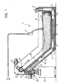
- a self-cleaning vacuum filter according to the invention, generally indicated 1, comprises essentially a tank 2 which is intended to be supplied with the liquid to be filtered from a collector 3 and has a filter bed, generally indicated 4, at its bottom.
- the filter bed 4 includes a filter screen 5 defining the top of a vacuum chamber 6 which is connected by a bottom side connector, not shown, to the suction side of an electric pump whose delivery is connected to a circuit for supplying the filtered liquid to the user.
- the filter bed 4 also includes an endless loop of regenerable filter cloth 7 which passes around idle return rollers 8, 9, 10, 11 and defines between them an active outward pass 7a, whose central horizontal portion bears on the screen 5 substantially with lateral sealing, and a return pass 7b.
- the arrangement of the rollers 8-11 is such that the surface (indicated 7c in Figure 2) of the loop defined by the cloth 7, on which the filtered material is deposited, always faces outwardly of the loop. This is due to the fact that the return pass 7b extends beneath the vacuum chamber 6.
- the filter cloth 7 is movable over the screen 5 of the filter bed 4 in steps by an entrainment system including a pair of endless chains 12 which pass round respective sprockets, of which that indicated 13 is rotated by an electric motor 14.
- the entrainment system operated by the chains 12 is similar to that described in the prior European patent application cited above and, for brevity, will therefore not be described in detail.
- the station for the removal of the filtered material from the cloth 7 is generally indicated 15 and, naturally, is downstream of the filter bed 4 relative to the direction of advance, indicated A, of the cloth.
- the removal station 15 is arranged above one end of the tank 2 and includes a drying unit 16 beneath an ascending slope of the pass 7a of the belt 7, the return roller 10 near which a descending slope of the return pass 7b starts, and a rotary removal roller 17.
- the drying unit 16 includes, also in a manner known from the prior European patent application mentioned above, a grid 18 on which the ascending slope of the pass 7a of the cloth 7 bears and which defines a vacuum chamber 19 connected to a pneumatic vacuum source, not shown.
- the drying unit 16 dries the filtered material deposited on the pass 7a of the cloth 7 in order to facilitate its subsequent at least partial removal as a result of the passage of the cloth 7 around the return roller 10.
- the removal is completed by the rotary roller 17 which is downstream of the return roller 10 relative to the direction of advance A of the cloth 7 and extends transverse the latter with its cylindrical wall substantially in contact with the surface 7c on which the filtered material is deposited.
- the cylindrical wall of the roller 17 may in fact be spaced slightly (for example, by a few microns) from the surface 7c.
- the removal roller 17 is rotated by an independent electric motor 20 at high speed, normally faster than 2500 revolutions per minute, in a sense B which may or may not correspond to the direction of advance A of the cloth 7.
- the cylindrical wall of the roller 17 may be smooth, grooved or knurled.
- a scraper member 21 with an inclined blade that interacts with the deposition surface 7c of the cloth 7 may also be provided between the return roller 10 and the removal roller 17.
- the lubricating and cooling liquid to be filtered is admitted to the tank 2 from above and is drawn into the vacuum chamber 6 through the screen 5 and the portion of the cloth 7 held thereon by the chains 12. Whilst the filtered liquid is recycled from the chamber 6 to the lubricating and cooling circuits of the associated machine tools, the filtered material is collected on that portion of the cloth 7. As soon as the degree of vacuum in the chamber 6 reaches a predetermined threshold, a signal is generated to enable the geared motor unit 14 to be activated to advance the cloth 7, entrained by the chains 12, by a predetermined distance. A clean portion of the cloth 17 is thus positioned in correspondence with the filter bed 4 whilst the previous portion is moved towards the removal station 15.
- the filtered material is then dried by the unit 16 and the subsequent advance of the cloth 7 causes most of the material to be removed therefrom as a result of passage of the cloth around the return roller 10.
- the removal of the filtered material is completed by the action of the roller 17 and by any scraper 21, the high-speed rotation of the roller 17 (normally in synchronism with the advance of the cloth 7) completely removing any remaining particles. This removal takes place by a fluid-dynamic effect of the suction created by the vacuum in the region between the surface 7c of the cloth 7 and the cylindrical wall of the roller 17 which is very close to it.
- the filtered material removed is then collected in a container 22 beneath the removal station 15.
- FIG. 3 shows a different way in which the removal roller 17 can be applied to a filter of a different type from that described above, in which the return pass 7b of the filter cloth 7 extends above the active pass 7a.
- two further return rollers 23, 24 are provided downstream of the return roller 10 relative to the direction of advance A of the cloth 7 and they cause the initial portion of the return pass 7b to follow the path shown in the drawing.
- the rotary roller 17 is again disposed downstream of the return roller 10 and a compressed-air supply unit 25 is interposed between the two rollers 10 and 17.
- the filtered material removed from the surface 7c of the cloth 7 is collected by a chute 26 and taken away by a screw conveyor 27.
Landscapes
- Chemical & Material Sciences (AREA)
- Chemical Kinetics & Catalysis (AREA)
- Filtration Of Liquid (AREA)
- Cleaning In General (AREA)
- Lubricants (AREA)
Applications Claiming Priority (2)
| Application Number | Priority Date | Filing Date | Title |
|---|---|---|---|
| IT67831A IT1240988B (it) | 1990-10-26 | 1990-10-26 | Filtro a depressione autopulente, particolarmente per la filtrazione di liquidi lubro-refrigeranti industriali |
| IT6783190 | 1990-10-26 |
Publications (3)
| Publication Number | Publication Date |
|---|---|
| EP0483073A2 true EP0483073A2 (de) | 1992-04-29 |
| EP0483073A3 EP0483073A3 (en) | 1993-12-08 |
| EP0483073B1 EP0483073B1 (de) | 1995-11-15 |
Family
ID=11305621
Family Applications (1)
| Application Number | Title | Priority Date | Filing Date |
|---|---|---|---|
| EP91830041A Expired - Lifetime EP0483073B1 (de) | 1990-10-26 | 1991-02-12 | Selbstreinigendes Vakuumfilter, besonders zur Filtration industrieller Schmier- und Kühlmittel |
Country Status (5)
| Country | Link |
|---|---|
| US (1) | US5118420A (de) |
| EP (1) | EP0483073B1 (de) |
| DE (1) | DE69114667T2 (de) |
| ES (1) | ES2082958T3 (de) |
| IT (1) | IT1240988B (de) |
Cited By (2)
| Publication number | Priority date | Publication date | Assignee | Title |
|---|---|---|---|---|
| EP0569108A1 (de) * | 1992-05-06 | 1993-11-10 | Bürener Maschinenfabrik GmbH | Vorrichtung zum Reinigen von Kühlschmierstoffen |
| FR2696108A1 (fr) * | 1992-09-25 | 1994-04-01 | Faivre Philippe | Procédé de traitement en continu de liquides industriels du domaine agro-alimentaire par filtration sans intermittence. |
Families Citing this family (7)
| Publication number | Priority date | Publication date | Assignee | Title |
|---|---|---|---|---|
| US5601729A (en) * | 1991-12-24 | 1997-02-11 | Filtra-Systems Company | Filter apparatus and method with media edge sealing |
| US5985145A (en) * | 1998-10-01 | 1999-11-16 | Henry Filters, Inc. | Shaft mounted gear box |
| US6612445B2 (en) * | 2001-03-29 | 2003-09-02 | Jack R. Bratten | Industrial filter with arrangement for removing machining chips from coolant prior to filtering |
| DE102004032334B3 (de) * | 2004-07-02 | 2005-10-20 | Mayfran Int Bv | Vorrichtung zur Aufnahme und Trennung von an Werkzeugmaschinen anfallenden Spänen und Kühlflüssigkeit (Transport) |
| US20100089816A1 (en) * | 2008-10-09 | 2010-04-15 | Mann+Hummel Gmbh | Liquid filter apparatus |
| US20110079562A1 (en) * | 2009-10-02 | 2011-04-07 | James Alexander Stark | Liquid separation using relative motion and fluid effects |
| US11724217B2 (en) * | 2017-01-23 | 2023-08-15 | Schlumberger Technology Corporation | Fluid and solid material separator |
Family Cites Families (6)
| Publication number | Priority date | Publication date | Assignee | Title |
|---|---|---|---|---|
| DE500997C (de) * | 1931-05-12 | Buckau R Wolf Akt Ges Maschf | Abnahmevorrichtung fuer die Filterschicht oder Stoffbahn bei Trommelfilter | |
| US2471517A (en) * | 1946-04-15 | 1949-05-31 | Edmund L Chaffee | Machine for separating spent hops from wort |
| BE638824A (de) * | 1963-10-08 | |||
| US3789985A (en) * | 1966-09-09 | 1974-02-05 | W Eakins | Apparatus and method for continuous filtering |
| DE1956334U (de) * | 1967-01-14 | 1967-03-02 | Braunschweigische Maschb Ansta | Reinigungseinrichtung fuer drehfilter. |
| IT1232132B (it) * | 1989-07-05 | 1992-01-23 | Gi Pi S A S Di Alfonso Gallett | Filtro a depressione autopulente con mezzo filtrante permanente continuo, particolarmente per liquidi lubro-refrigeranti industriali |
-
1990
- 1990-10-26 IT IT67831A patent/IT1240988B/it active IP Right Grant
-
1991
- 1991-02-12 ES ES91830041T patent/ES2082958T3/es not_active Expired - Lifetime
- 1991-02-12 EP EP91830041A patent/EP0483073B1/de not_active Expired - Lifetime
- 1991-02-12 DE DE69114667T patent/DE69114667T2/de not_active Expired - Fee Related
- 1991-02-19 US US07/656,373 patent/US5118420A/en not_active Expired - Lifetime
Cited By (2)
| Publication number | Priority date | Publication date | Assignee | Title |
|---|---|---|---|---|
| EP0569108A1 (de) * | 1992-05-06 | 1993-11-10 | Bürener Maschinenfabrik GmbH | Vorrichtung zum Reinigen von Kühlschmierstoffen |
| FR2696108A1 (fr) * | 1992-09-25 | 1994-04-01 | Faivre Philippe | Procédé de traitement en continu de liquides industriels du domaine agro-alimentaire par filtration sans intermittence. |
Also Published As
| Publication number | Publication date |
|---|---|
| DE69114667D1 (de) | 1995-12-21 |
| EP0483073B1 (de) | 1995-11-15 |
| IT1240988B (it) | 1993-12-27 |
| IT9067831A0 (it) | 1990-10-26 |
| IT9067831A1 (it) | 1992-04-26 |
| DE69114667T2 (de) | 1996-04-18 |
| ES2082958T3 (es) | 1996-04-01 |
| EP0483073A3 (en) | 1993-12-08 |
| US5118420A (en) | 1992-06-02 |
Similar Documents
| Publication | Publication Date | Title |
|---|---|---|
| US3486309A (en) | Fiber waste disposal system for textile machines | |
| EP0286328B1 (de) | Gerät zum Nassreinigen einer Fussbodenfläche oder Wandfläche | |
| US6511152B2 (en) | Inkjet printer with cleaning means | |
| EP0483073B1 (de) | Selbstreinigendes Vakuumfilter, besonders zur Filtration industrieller Schmier- und Kühlmittel | |
| US4647298A (en) | Electrostatic powder recovery installation | |
| US3924397A (en) | Apparatus for removing impurities from fibrous material | |
| CA2093065C (en) | Apparatus for filtering debris from a moving airstream | |
| EP0026069B1 (de) | Vorrichtung und Verfahren zur Abscheidung feinzerteilter Materialien aus einem flüssigen Medium | |
| KR20130050913A (ko) | 필터 세정 방법 및 그 장치 | |
| GB1456816A (en) | Apparatus for cleaning a rotating brush particularly in a textile machine | |
| EP0407363B1 (de) | Selbstreinigender Unterdruckfilter mit dauerndem endlosem Bandfiltermedium, insbesondere zur Reinigung von industriellen Schmier- und Kühlflüssigkeiten | |
| KR101580396B1 (ko) | Pcb기판 제조공정 중 세척 후 건조공정에서의 이물질 제거방법 및 그 장치 | |
| US5569382A (en) | Belt filter device having a cleaning spray head | |
| US4300476A (en) | Apparatus for the stiffening of textile sheets by coating with plastic | |
| US5256290A (en) | Coolant filtration unit with sludge dryer | |
| US4461633A (en) | Air filtering machinery with variable speed cleaning | |
| US3055038A (en) | Traveling cleaning apparatus | |
| ES8607432A1 (es) | Perfeccionamientos en los limpiadores desplazables para lim-piar instalaciones textiles y metodo correspondiente | |
| EP0389045B1 (de) | Filtervorrichtung zum Abtrennen von Staub aus einem luftförmigen Fluid und insbesondere zum Abscheiden von Textilstaub | |
| JPS609846B2 (ja) | 空気浄化装置 | |
| US2875846A (en) | Differential pressure cleaning apparatus | |
| IL33230A (en) | Fabric dampener | |
| KR102044316B1 (ko) | 스트립 방향전환 롤 표면의 이물질 제거장치 | |
| US3469703A (en) | Method and apparatus for regenerating the filter cloth of a rotary filter table | |
| US5568822A (en) | Film cleaning system and method for photographic film |
Legal Events
| Date | Code | Title | Description |
|---|---|---|---|
| PUAI | Public reference made under article 153(3) epc to a published international application that has entered the european phase |
Free format text: ORIGINAL CODE: 0009012 |
|
| AK | Designated contracting states |
Kind code of ref document: A2 Designated state(s): DE ES FR GB IT SE |
|
| PUAL | Search report despatched |
Free format text: ORIGINAL CODE: 0009013 |
|
| AK | Designated contracting states |
Kind code of ref document: A3 Designated state(s): DE ES FR GB IT SE |
|
| 17P | Request for examination filed |
Effective date: 19940316 |
|
| 17Q | First examination report despatched |
Effective date: 19940715 |
|
| GRAA | (expected) grant |
Free format text: ORIGINAL CODE: 0009210 |
|
| AK | Designated contracting states |
Kind code of ref document: B1 Designated state(s): DE ES FR GB IT SE |
|
| ITF | It: translation for a ep patent filed | ||
| REF | Corresponds to: |
Ref document number: 69114667 Country of ref document: DE Date of ref document: 19951221 |
|
| ET | Fr: translation filed | ||
| REG | Reference to a national code |
Ref country code: ES Ref legal event code: FG2A Ref document number: 2082958 Country of ref document: ES Kind code of ref document: T3 |
|
| PLBE | No opposition filed within time limit |
Free format text: ORIGINAL CODE: 0009261 |
|
| STAA | Information on the status of an ep patent application or granted ep patent |
Free format text: STATUS: NO OPPOSITION FILED WITHIN TIME LIMIT |
|
| 26N | No opposition filed | ||
| REG | Reference to a national code |
Ref country code: GB Ref legal event code: IF02 |
|
| PG25 | Lapsed in a contracting state [announced via postgrant information from national office to epo] |
Ref country code: IT Free format text: LAPSE BECAUSE OF NON-PAYMENT OF DUE FEES;WARNING: LAPSES OF ITALIAN PATENTS WITH EFFECTIVE DATE BEFORE 2007 MAY HAVE OCCURRED AT ANY TIME BEFORE 2007. THE CORRECT EFFECTIVE DATE MAY BE DIFFERENT FROM THE ONE RECORDED. Effective date: 20050212 |
|
| PGFP | Annual fee paid to national office [announced via postgrant information from national office to epo] |
Ref country code: SE Payment date: 20050215 Year of fee payment: 15 |
|
| PG25 | Lapsed in a contracting state [announced via postgrant information from national office to epo] |
Ref country code: SE Free format text: LAPSE BECAUSE OF NON-PAYMENT OF DUE FEES Effective date: 20060213 |
|
| EUG | Se: european patent has lapsed | ||
| PGFP | Annual fee paid to national office [announced via postgrant information from national office to epo] |
Ref country code: ES Payment date: 20080324 Year of fee payment: 18 |
|
| PGRI | Patent reinstated in contracting state [announced from national office to epo] |
Ref country code: IT Effective date: 20080301 |
|
| PGFP | Annual fee paid to national office [announced via postgrant information from national office to epo] |
Ref country code: IT Payment date: 20080208 Year of fee payment: 18 Ref country code: GB Payment date: 20080206 Year of fee payment: 18 Ref country code: DE Payment date: 20080207 Year of fee payment: 18 |
|
| PGFP | Annual fee paid to national office [announced via postgrant information from national office to epo] |
Ref country code: FR Payment date: 20080208 Year of fee payment: 18 |
|
| GBPC | Gb: european patent ceased through non-payment of renewal fee |
Effective date: 20090212 |
|
| REG | Reference to a national code |
Ref country code: FR Ref legal event code: ST Effective date: 20091030 |
|
| PG25 | Lapsed in a contracting state [announced via postgrant information from national office to epo] |
Ref country code: DE Free format text: LAPSE BECAUSE OF NON-PAYMENT OF DUE FEES Effective date: 20090901 |
|
| REG | Reference to a national code |
Ref country code: ES Ref legal event code: FD2A Effective date: 20090213 |
|
| PG25 | Lapsed in a contracting state [announced via postgrant information from national office to epo] |
Ref country code: GB Free format text: LAPSE BECAUSE OF NON-PAYMENT OF DUE FEES Effective date: 20090212 Ref country code: FR Free format text: LAPSE BECAUSE OF NON-PAYMENT OF DUE FEES Effective date: 20090302 |
|
| PG25 | Lapsed in a contracting state [announced via postgrant information from national office to epo] |
Ref country code: ES Free format text: LAPSE BECAUSE OF NON-PAYMENT OF DUE FEES Effective date: 20090213 |
|
| PG25 | Lapsed in a contracting state [announced via postgrant information from national office to epo] |
Ref country code: IT Free format text: LAPSE BECAUSE OF NON-PAYMENT OF DUE FEES Effective date: 20090212 |