EP0483080A1 - Dispositif pour fixer des composants électroniques de puissance à un réfroidisseur - Google Patents
Dispositif pour fixer des composants électroniques de puissance à un réfroidisseur Download PDFInfo
- Publication number
- EP0483080A1 EP0483080A1 EP91830434A EP91830434A EP0483080A1 EP 0483080 A1 EP0483080 A1 EP 0483080A1 EP 91830434 A EP91830434 A EP 91830434A EP 91830434 A EP91830434 A EP 91830434A EP 0483080 A1 EP0483080 A1 EP 0483080A1
- Authority
- EP
- European Patent Office
- Prior art keywords
- bar
- clamping
- power components
- dissipator
- components
- Prior art date
- Legal status (The legal status is an assumption and is not a legal conclusion. Google has not performed a legal analysis and makes no representation as to the accuracy of the status listed.)
- Withdrawn
Links
Images

Classifications
-
- H—ELECTRICITY
- H10—SEMICONDUCTOR DEVICES; ELECTRIC SOLID-STATE DEVICES NOT OTHERWISE PROVIDED FOR
- H10W—GENERIC PACKAGES, INTERCONNECTIONS, CONNECTORS OR OTHER CONSTRUCTIONAL DETAILS OF DEVICES COVERED BY CLASS H10
- H10W40/00—Arrangements for thermal protection or thermal control
- H10W40/60—Securing means for detachable heating or cooling arrangements, e.g. clamps
- H10W40/611—Bolts or screws
-
- H—ELECTRICITY
- H10—SEMICONDUCTOR DEVICES; ELECTRIC SOLID-STATE DEVICES NOT OTHERWISE PROVIDED FOR
- H10W—GENERIC PACKAGES, INTERCONNECTIONS, CONNECTORS OR OTHER CONSTRUCTIONAL DETAILS OF DEVICES COVERED BY CLASS H10
- H10W40/00—Arrangements for thermal protection or thermal control
- H10W40/20—Arrangements for cooling
- H10W40/231—Arrangements for cooling characterised by their places of attachment or cooling paths
- H10W40/235—Arrangements for cooling characterised by their places of attachment or cooling paths attached to package parts
-
- H—ELECTRICITY
- H10—SEMICONDUCTOR DEVICES; ELECTRIC SOLID-STATE DEVICES NOT OTHERWISE PROVIDED FOR
- H10W—GENERIC PACKAGES, INTERCONNECTIONS, CONNECTORS OR OTHER CONSTRUCTIONAL DETAILS OF DEVICES COVERED BY CLASS H10
- H10W40/00—Arrangements for thermal protection or thermal control
- H10W40/60—Securing means for detachable heating or cooling arrangements, e.g. clamps
- H10W40/625—Clamping parts not primarily conducting heat
Definitions
- the present invention relates to a device for fixing electronic power components to a heat dissipator.
- the fixing of electronic power components, for example transistors, to a heat dissipator, a finned plate or an integral part of a metal container in which there is an electronic monitoring unit requires an intimate contact between the component and the dissipator in order to allow optimum transmission of the heat.
- the problem of providing an optimum contact between power components and dissipator is resolved according to the present invention by virtue of a bar of polymeric material provided with means for clamping it against the dissipator and a lateral rebate in correspondence with which the power components are clamped against the heat dissipator.
- the bar includes in correspondence with the lateral rebate a plurality of transverse notches disposed substantially between the power components and adapted to allow a distribution of the clamping pressures of the components.
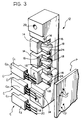
- reference numeral 10 generally designates a device for fixing electronic power components C, for example power transistors, to a heat dissipator D.
- the device comprises a prismatic bar 12 of quadrangular cross-section, made from polymeric material with a mineral filler in order to withstand high temperatures and having in one of its lateral walls 12a a rebate 14 against which are clamped the portions C1 of the power components C.
- the bar 12 also has a series of transverse notches 16 disposed at right-angles to the rebate 14 between the power components C and, in correspondence with each clamping zone of the relative power component C, a transverse bore 18 which is disposed substantially between two adjacent notches 16.
- the bar 12 has in correspondence with the ends 12a two fixing holes 20 adapted to cooperate with screws 22 for clamping the bar 12 against the surface S of the metal heat dissipator D which, in the form of embodiment shown in the drawings, corresponds to the walls of a metal container A housing the electronic monitoring unit (not illustrated) of which the power components C form part.
- Each of the said components has a portion C2 adjacent the clamping portion C1 placed on a step 24 formed in the rebate 14 between pairs of notches 16 ( Figures 2-3) and the rheophores R of each power component C are inserted into appropriate bores F in a printed circuit board P disposed in the container A.
- the presence of the notches 16 makes it possible to obtain a good distribution of clamping pressures over the components C.
- the transverse bores 18 in the bar 12 is correspondence with the components C integrate the function of the notches 16 by guaranteeing elasticity in the clamping of the components, an elasticity which is due to the reversed arc conformation of zones 26 of the bar which are capable of clamping the portions C1 of the power components C.
Landscapes
- Cooling Or The Like Of Electrical Apparatus (AREA)
- Non-Reversible Transmitting Devices (AREA)
- Cooling Or The Like Of Semiconductors Or Solid State Devices (AREA)
Applications Claiming Priority (2)
| Application Number | Priority Date | Filing Date | Title |
|---|---|---|---|
| IT5332290U | 1990-10-22 | ||
| IT53322U IT220643Z2 (it) | 1990-10-22 | 1990-10-22 | Dispositivo di fissaggio di componenti elettronici di potenza ad un dissipatore termico |
Publications (1)
| Publication Number | Publication Date |
|---|---|
| EP0483080A1 true EP0483080A1 (fr) | 1992-04-29 |
Family
ID=11281785
Family Applications (1)
| Application Number | Title | Priority Date | Filing Date |
|---|---|---|---|
| EP91830434A Withdrawn EP0483080A1 (fr) | 1990-10-22 | 1991-10-15 | Dispositif pour fixer des composants électroniques de puissance à un réfroidisseur |
Country Status (2)
| Country | Link |
|---|---|
| EP (1) | EP0483080A1 (fr) |
| IT (1) | IT220643Z2 (fr) |
Cited By (2)
| Publication number | Priority date | Publication date | Assignee | Title |
|---|---|---|---|---|
| CN103391703A (zh) * | 2012-05-11 | 2013-11-13 | 控制技术有限公司 | 夹紧装置 |
| DE102018008936B4 (de) | 2017-12-19 | 2022-08-25 | Fanuc Corporation | Elektronische Bauteileinheit |
Citations (1)
| Publication number | Priority date | Publication date | Assignee | Title |
|---|---|---|---|---|
| EP0254692A1 (fr) * | 1986-07-17 | 1988-01-27 | STMicroelectronics S.r.l. | Equipement de semi-conducteur monté dans un boîtier hautement flexible et segmenté, pourvu d'un drain de chaleur |
-
1990
- 1990-10-22 IT IT53322U patent/IT220643Z2/it active IP Right Grant
-
1991
- 1991-10-15 EP EP91830434A patent/EP0483080A1/fr not_active Withdrawn
Patent Citations (1)
| Publication number | Priority date | Publication date | Assignee | Title |
|---|---|---|---|---|
| EP0254692A1 (fr) * | 1986-07-17 | 1988-01-27 | STMicroelectronics S.r.l. | Equipement de semi-conducteur monté dans un boîtier hautement flexible et segmenté, pourvu d'un drain de chaleur |
Cited By (2)
| Publication number | Priority date | Publication date | Assignee | Title |
|---|---|---|---|---|
| CN103391703A (zh) * | 2012-05-11 | 2013-11-13 | 控制技术有限公司 | 夹紧装置 |
| DE102018008936B4 (de) | 2017-12-19 | 2022-08-25 | Fanuc Corporation | Elektronische Bauteileinheit |
Also Published As
| Publication number | Publication date |
|---|---|
| IT9053322U1 (it) | 1992-04-22 |
| IT220643Z2 (it) | 1993-10-07 |
| IT9053322V0 (it) | 1990-10-22 |
Similar Documents
| Publication | Publication Date | Title |
|---|---|---|
| US4019099A (en) | Circuit board mounting device | |
| GB2278503A (en) | Self-locking heat sinks for surface mount devices | |
| EP0664581A3 (fr) | Connecteur à profil bas pour l'interconnexion de deux cartes de circuits imprimés. | |
| BR9006918A (pt) | Processo para formar,eletroliticamente,uma lamina de cobre para aplicacoes em quadro de circuito impresso,banho eletrolitico para depositar,eletroliticamente,lamina de cobre para aplicacao em quadro de circuito impresso e lamina de cobre | |
| BR9005384A (pt) | Placa de circuito impresso,processo para sua fabricacao e processo para a fixacao de pecas eletronicas a mesma | |
| US4931679A (en) | Printed circuit board components with alternate mounting modes | |
| ATE80763T1 (de) | Elektronik-baugruppe. | |
| EP0844808A3 (fr) | Dispositif pour circuit imprimé | |
| KR960012060A (ko) | 커패시터 장착용 조립체 | |
| US6084192A (en) | Slide knob mounting structure | |
| KR960006734A (ko) | 무선 주파 방해 개스킷 | |
| WO1991019420A3 (fr) | Dispositif a ressorts d'arret multiples et procede de fabrication du dispositif | |
| KR930011331A (ko) | 전기 접속기 | |
| FR2719754B1 (fr) | Dispositif de verrouillage/déverrouillage en translation d'une rallonge par rapport à un élément de mobilier et élément de mobilier ainsi équipé. | |
| DE59300799D1 (de) | Leiterkarte für eine Leistungshalbleiter aufweisende Leistungselektronikschaltung. | |
| JPH0126200B2 (fr) | ||
| KR200149151Y1 (ko) | 기판부착용 방열체 | |
| WO2001062057A1 (fr) | Radiateur a dispositif integre de fixation des composants | |
| IT9053322U1 (it) | Dispositivo di fissaggio di componenti elettronici di potenza ad un dissipatore termico | |
| FR2670074B1 (fr) | Connexion entre des composants smd et une carte de circuits imprimes. | |
| US5190097A (en) | Integrated clamping device for component heatsinking | |
| EP0709885A3 (fr) | Plaque à circuits imprimés comprenant un système de refroidissement intégré à boucle fermée | |
| ES2186470A1 (es) | Maquina para la mecanizacion y/o fabricacion de objetos. | |
| KR0126452Y1 (ko) | 전원공급장치 | |
| JPS583330Y2 (ja) | プリント基板の位置決め装置 |
Legal Events
| Date | Code | Title | Description |
|---|---|---|---|
| PUAI | Public reference made under article 153(3) epc to a published international application that has entered the european phase |
Free format text: ORIGINAL CODE: 0009012 |
|
| AK | Designated contracting states |
Kind code of ref document: A1 Designated state(s): DE ES FR GB SE |
|
| STAA | Information on the status of an ep patent application or granted ep patent |
Free format text: STATUS: THE APPLICATION IS DEEMED TO BE WITHDRAWN |
|
| 18D | Application deemed to be withdrawn |
Effective date: 19921030 |