EP0483153B2 - Procede de formage de tubes par l'application d'aspiration et de pression pneumatique a la surface du mandrin de refroidissement - Google Patents
Procede de formage de tubes par l'application d'aspiration et de pression pneumatique a la surface du mandrin de refroidissement Download PDFInfo
- Publication number
- EP0483153B2 EP0483153B2 EP90906818A EP90906818A EP0483153B2 EP 0483153 B2 EP0483153 B2 EP 0483153B2 EP 90906818 A EP90906818 A EP 90906818A EP 90906818 A EP90906818 A EP 90906818A EP 0483153 B2 EP0483153 B2 EP 0483153B2
- Authority
- EP
- European Patent Office
- Prior art keywords
- plug
- tube
- mold
- wall
- pneumatic pressure
- Prior art date
- Legal status (The legal status is an assumption and is not a legal conclusion. Google has not performed a legal analysis and makes no representation as to the accuracy of the status listed.)
- Expired - Lifetime
Links
- 238000000034 method Methods 0.000 title claims description 13
- 238000001816 cooling Methods 0.000 title abstract description 27
- 229920001169 thermoplastic Polymers 0.000 claims abstract description 5
- 239000004416 thermosoftening plastic Substances 0.000 claims abstract description 5
- 238000011144 upstream manufacturing Methods 0.000 claims description 8
- 239000012815 thermoplastic material Substances 0.000 claims description 6
- 238000004891 communication Methods 0.000 claims description 5
- 239000012530 fluid Substances 0.000 claims description 5
- 238000004513 sizing Methods 0.000 abstract description 12
- 238000001125 extrusion Methods 0.000 description 15
- 230000015572 biosynthetic process Effects 0.000 description 13
- 239000004033 plastic Substances 0.000 description 9
- 229920003023 plastic Polymers 0.000 description 9
- 239000000463 material Substances 0.000 description 7
- 238000007373 indentation Methods 0.000 description 4
- 239000007788 liquid Substances 0.000 description 4
- 230000000712 assembly Effects 0.000 description 3
- 238000000429 assembly Methods 0.000 description 3
- 239000000110 cooling liquid Substances 0.000 description 3
- 239000000498 cooling water Substances 0.000 description 3
- 230000000694 effects Effects 0.000 description 3
- 238000005461 lubrication Methods 0.000 description 3
- 238000000465 moulding Methods 0.000 description 3
- XLYOFNOQVPJJNP-UHFFFAOYSA-N water Substances O XLYOFNOQVPJJNP-UHFFFAOYSA-N 0.000 description 3
- CURLTUGMZLYLDI-UHFFFAOYSA-N Carbon dioxide Chemical compound O=C=O CURLTUGMZLYLDI-UHFFFAOYSA-N 0.000 description 2
- 238000005266 casting Methods 0.000 description 2
- 239000012809 cooling fluid Substances 0.000 description 2
- 238000004519 manufacturing process Methods 0.000 description 2
- 238000012986 modification Methods 0.000 description 2
- 230000004048 modification Effects 0.000 description 2
- 229910002092 carbon dioxide Inorganic materials 0.000 description 1
- 239000001569 carbon dioxide Substances 0.000 description 1
- 230000000295 complement effect Effects 0.000 description 1
- 230000009969 flowable effect Effects 0.000 description 1
- -1 for example Substances 0.000 description 1
- 238000009472 formulation Methods 0.000 description 1
- 238000009499 grossing Methods 0.000 description 1
- 239000000314 lubricant Substances 0.000 description 1
- 230000001050 lubricating effect Effects 0.000 description 1
- 238000012423 maintenance Methods 0.000 description 1
- 239000000203 mixture Substances 0.000 description 1
- 230000002093 peripheral effect Effects 0.000 description 1
- 230000000750 progressive effect Effects 0.000 description 1
- 230000000717 retained effect Effects 0.000 description 1
- 230000001020 rhythmical effect Effects 0.000 description 1
Images




Classifications
-
- B—PERFORMING OPERATIONS; TRANSPORTING
- B29—WORKING OF PLASTICS; WORKING OF SUBSTANCES IN A PLASTIC STATE IN GENERAL
- B29C—SHAPING OR JOINING OF PLASTICS; SHAPING OF MATERIAL IN A PLASTIC STATE, NOT OTHERWISE PROVIDED FOR; AFTER-TREATMENT OF THE SHAPED PRODUCTS, e.g. REPAIRING
- B29C49/00—Blow-moulding, i.e. blowing a preform or parison to a desired shape within a mould; Apparatus therefor
- B29C49/0015—Making articles of indefinite length, e.g. corrugated tubes
- B29C49/0021—Making articles of indefinite length, e.g. corrugated tubes using moulds or mould parts movable in a closed path, e.g. mounted on movable endless supports
-
- B—PERFORMING OPERATIONS; TRANSPORTING
- B29—WORKING OF PLASTICS; WORKING OF SUBSTANCES IN A PLASTIC STATE IN GENERAL
- B29C—SHAPING OR JOINING OF PLASTICS; SHAPING OF MATERIAL IN A PLASTIC STATE, NOT OTHERWISE PROVIDED FOR; AFTER-TREATMENT OF THE SHAPED PRODUCTS, e.g. REPAIRING
- B29C48/00—Extrusion moulding, i.e. expressing the moulding material through a die or nozzle which imparts the desired form; Apparatus therefor
- B29C48/03—Extrusion moulding, i.e. expressing the moulding material through a die or nozzle which imparts the desired form; Apparatus therefor characterised by the shape of the extruded material at extrusion
- B29C48/09—Articles with cross-sections having partially or fully enclosed cavities, e.g. pipes or channels
-
- B—PERFORMING OPERATIONS; TRANSPORTING
- B29—WORKING OF PLASTICS; WORKING OF SUBSTANCES IN A PLASTIC STATE IN GENERAL
- B29C—SHAPING OR JOINING OF PLASTICS; SHAPING OF MATERIAL IN A PLASTIC STATE, NOT OTHERWISE PROVIDED FOR; AFTER-TREATMENT OF THE SHAPED PRODUCTS, e.g. REPAIRING
- B29C48/00—Extrusion moulding, i.e. expressing the moulding material through a die or nozzle which imparts the desired form; Apparatus therefor
- B29C48/03—Extrusion moulding, i.e. expressing the moulding material through a die or nozzle which imparts the desired form; Apparatus therefor characterised by the shape of the extruded material at extrusion
- B29C48/13—Articles with a cross-section varying in the longitudinal direction, e.g. corrugated pipes
-
- B—PERFORMING OPERATIONS; TRANSPORTING
- B29—WORKING OF PLASTICS; WORKING OF SUBSTANCES IN A PLASTIC STATE IN GENERAL
- B29C—SHAPING OR JOINING OF PLASTICS; SHAPING OF MATERIAL IN A PLASTIC STATE, NOT OTHERWISE PROVIDED FOR; AFTER-TREATMENT OF THE SHAPED PRODUCTS, e.g. REPAIRING
- B29C48/00—Extrusion moulding, i.e. expressing the moulding material through a die or nozzle which imparts the desired form; Apparatus therefor
- B29C48/25—Component parts, details or accessories; Auxiliary operations
- B29C48/30—Extrusion nozzles or dies
- B29C48/303—Extrusion nozzles or dies using dies or die parts movable in a closed circuit, e.g. mounted on movable endless support
-
- B—PERFORMING OPERATIONS; TRANSPORTING
- B29—WORKING OF PLASTICS; WORKING OF SUBSTANCES IN A PLASTIC STATE IN GENERAL
- B29C—SHAPING OR JOINING OF PLASTICS; SHAPING OF MATERIAL IN A PLASTIC STATE, NOT OTHERWISE PROVIDED FOR; AFTER-TREATMENT OF THE SHAPED PRODUCTS, e.g. REPAIRING
- B29C48/00—Extrusion moulding, i.e. expressing the moulding material through a die or nozzle which imparts the desired form; Apparatus therefor
- B29C48/25—Component parts, details or accessories; Auxiliary operations
- B29C48/88—Thermal treatment of the stream of extruded material, e.g. cooling
- B29C48/90—Thermal treatment of the stream of extruded material, e.g. cooling with calibration or sizing, i.e. combined with fixing or setting of the final dimensions of the extruded article
- B29C48/901—Thermal treatment of the stream of extruded material, e.g. cooling with calibration or sizing, i.e. combined with fixing or setting of the final dimensions of the extruded article of hollow bodies
- B29C48/902—Thermal treatment of the stream of extruded material, e.g. cooling with calibration or sizing, i.e. combined with fixing or setting of the final dimensions of the extruded article of hollow bodies internally
-
- B—PERFORMING OPERATIONS; TRANSPORTING
- B29—WORKING OF PLASTICS; WORKING OF SUBSTANCES IN A PLASTIC STATE IN GENERAL
- B29C—SHAPING OR JOINING OF PLASTICS; SHAPING OF MATERIAL IN A PLASTIC STATE, NOT OTHERWISE PROVIDED FOR; AFTER-TREATMENT OF THE SHAPED PRODUCTS, e.g. REPAIRING
- B29C48/00—Extrusion moulding, i.e. expressing the moulding material through a die or nozzle which imparts the desired form; Apparatus therefor
- B29C48/25—Component parts, details or accessories; Auxiliary operations
- B29C48/88—Thermal treatment of the stream of extruded material, e.g. cooling
- B29C48/90—Thermal treatment of the stream of extruded material, e.g. cooling with calibration or sizing, i.e. combined with fixing or setting of the final dimensions of the extruded article
- B29C48/908—Thermal treatment of the stream of extruded material, e.g. cooling with calibration or sizing, i.e. combined with fixing or setting of the final dimensions of the extruded article characterised by calibrator surface, e.g. structure or holes for lubrication, cooling or venting
-
- B—PERFORMING OPERATIONS; TRANSPORTING
- B29—WORKING OF PLASTICS; WORKING OF SUBSTANCES IN A PLASTIC STATE IN GENERAL
- B29C—SHAPING OR JOINING OF PLASTICS; SHAPING OF MATERIAL IN A PLASTIC STATE, NOT OTHERWISE PROVIDED FOR; AFTER-TREATMENT OF THE SHAPED PRODUCTS, e.g. REPAIRING
- B29C49/00—Blow-moulding, i.e. blowing a preform or parison to a desired shape within a mould; Apparatus therefor
- B29C49/22—Blow-moulding, i.e. blowing a preform or parison to a desired shape within a mould; Apparatus therefor using multilayered preforms or parisons
-
- B—PERFORMING OPERATIONS; TRANSPORTING
- B29—WORKING OF PLASTICS; WORKING OF SUBSTANCES IN A PLASTIC STATE IN GENERAL
- B29C—SHAPING OR JOINING OF PLASTICS; SHAPING OF MATERIAL IN A PLASTIC STATE, NOT OTHERWISE PROVIDED FOR; AFTER-TREATMENT OF THE SHAPED PRODUCTS, e.g. REPAIRING
- B29C48/00—Extrusion moulding, i.e. expressing the moulding material through a die or nozzle which imparts the desired form; Apparatus therefor
- B29C48/001—Combinations of extrusion moulding with other shaping operations
-
- B—PERFORMING OPERATIONS; TRANSPORTING
- B29—WORKING OF PLASTICS; WORKING OF SUBSTANCES IN A PLASTIC STATE IN GENERAL
- B29C—SHAPING OR JOINING OF PLASTICS; SHAPING OF MATERIAL IN A PLASTIC STATE, NOT OTHERWISE PROVIDED FOR; AFTER-TREATMENT OF THE SHAPED PRODUCTS, e.g. REPAIRING
- B29C48/00—Extrusion moulding, i.e. expressing the moulding material through a die or nozzle which imparts the desired form; Apparatus therefor
- B29C48/001—Combinations of extrusion moulding with other shaping operations
- B29C48/0011—Combinations of extrusion moulding with other shaping operations combined with compression moulding
-
- B—PERFORMING OPERATIONS; TRANSPORTING
- B29—WORKING OF PLASTICS; WORKING OF SUBSTANCES IN A PLASTIC STATE IN GENERAL
- B29C—SHAPING OR JOINING OF PLASTICS; SHAPING OF MATERIAL IN A PLASTIC STATE, NOT OTHERWISE PROVIDED FOR; AFTER-TREATMENT OF THE SHAPED PRODUCTS, e.g. REPAIRING
- B29C48/00—Extrusion moulding, i.e. expressing the moulding material through a die or nozzle which imparts the desired form; Apparatus therefor
- B29C48/001—Combinations of extrusion moulding with other shaping operations
- B29C48/002—Combinations of extrusion moulding with other shaping operations combined with surface shaping
-
- B—PERFORMING OPERATIONS; TRANSPORTING
- B29—WORKING OF PLASTICS; WORKING OF SUBSTANCES IN A PLASTIC STATE IN GENERAL
- B29C—SHAPING OR JOINING OF PLASTICS; SHAPING OF MATERIAL IN A PLASTIC STATE, NOT OTHERWISE PROVIDED FOR; AFTER-TREATMENT OF THE SHAPED PRODUCTS, e.g. REPAIRING
- B29C48/00—Extrusion moulding, i.e. expressing the moulding material through a die or nozzle which imparts the desired form; Apparatus therefor
- B29C48/16—Articles comprising two or more components, e.g. co-extruded layers
- B29C48/18—Articles comprising two or more components, e.g. co-extruded layers the components being layers
- B29C48/21—Articles comprising two or more components, e.g. co-extruded layers the components being layers the layers being joined at their surfaces
-
- B—PERFORMING OPERATIONS; TRANSPORTING
- B29—WORKING OF PLASTICS; WORKING OF SUBSTANCES IN A PLASTIC STATE IN GENERAL
- B29L—INDEXING SCHEME ASSOCIATED WITH SUBCLASS B29C, RELATING TO PARTICULAR ARTICLES
- B29L2016/00—Articles with corrugations or pleats
-
- B—PERFORMING OPERATIONS; TRANSPORTING
- B29—WORKING OF PLASTICS; WORKING OF SUBSTANCES IN A PLASTIC STATE IN GENERAL
- B29L—INDEXING SCHEME ASSOCIATED WITH SUBCLASS B29C, RELATING TO PARTICULAR ARTICLES
- B29L2023/00—Tubular articles
- B29L2023/18—Pleated or corrugated hoses
- B29L2023/183—Pleated or corrugated hoses partially
-
- B—PERFORMING OPERATIONS; TRANSPORTING
- B29—WORKING OF PLASTICS; WORKING OF SUBSTANCES IN A PLASTIC STATE IN GENERAL
- B29L—INDEXING SCHEME ASSOCIATED WITH SUBCLASS B29C, RELATING TO PARTICULAR ARTICLES
- B29L2023/00—Tubular articles
- B29L2023/18—Pleated or corrugated hoses
- B29L2023/186—Pleated or corrugated hoses having a smooth internal wall
-
- B—PERFORMING OPERATIONS; TRANSPORTING
- B29—WORKING OF PLASTICS; WORKING OF SUBSTANCES IN A PLASTIC STATE IN GENERAL
- B29L—INDEXING SCHEME ASSOCIATED WITH SUBCLASS B29C, RELATING TO PARTICULAR ARTICLES
- B29L2024/00—Articles with hollow walls
- B29L2024/003—Articles with hollow walls comprising corrugated cores
-
- B—PERFORMING OPERATIONS; TRANSPORTING
- B29—WORKING OF PLASTICS; WORKING OF SUBSTANCES IN A PLASTIC STATE IN GENERAL
- B29L—INDEXING SCHEME ASSOCIATED WITH SUBCLASS B29C, RELATING TO PARTICULAR ARTICLES
- B29L2031/00—Other particular articles
- B29L2031/60—Multitubular or multicompartmented articles, e.g. honeycomb
- B29L2031/601—Multi-tubular articles, i.e. composed of a plurality of tubes
Definitions
- the invention relates to apparatus for molding thermoplastic tubing having at least one bell therein in which a sizing plug is used to define internal diameter of the tubing.
- the invention is especially useful in the production of ribbed or double walled tubing.
- the apparatus is of the type in which tubing of thermoplastic material is continuously extruded into a travelling tubular mold tunnel about a mandrel and is confined to the shape of the pipe by a sizing plug downstream of the mandrel.
- a sizing plug downstream of the mandrel.
- Such a plug may, on some occasions, when the extrudate does not easily flow fully into the mold, be heated to increase the fluidity of the extrudate so that it may more easily flow into recesses of the mold, for example under the influence of suction from the bases of the recesses.
- more usually the extrudate is provided in sufficiently molten condition to flow fully into the mold. In this case it is necessary to provide a sizing plug to define the inner wall of the pipe so as to confine the extrudate in an appropriate casting cavity.
- a simple sizing plug defining the inner wall of a tube is described by Chaplain in U.S. Patent No. 4,365,948 issued December 28, 1982. Usually some temperature control is desirable in a sizing plug and Lupke in U.S. Patent No. 4,545,751 issued October 8, 1985 describes a more sophisticated arrangement. In that arrangement the sizing plug does not define an inner wall of the pipe but is used to distribute air into the inside of corrugated tubing. Pressured air is delivered through a central core coaxial with an extrusion nozzle. Hot peripheral air is drawn off and central cool air is permitted to leave the plug to contact the inside of corrugated pipe, the plug being inwardly spaced from the inner pipe wall.
- Such arrangement is suitable for use where corrugated tubing is involved but the range of temperature in cooling may be limited.
- the arrangement is less suitable where ribbed tubing is to be produced since the plug, in that case, should be a plug contacting the inside wall of the pipe to confine it into a casting region. When this is the case, air cannot be released between the plug wall and the inner pipe wall for cooling.
- a cooling plug suitable for use in the formulation of ribbed pipe is disclosed by Lupke in his later U.S. Patent No. 4,555,230 issued November 26, 1985. In that patent Lupke does not attempt to use released cooling air but provides within and near the surface of a follower plug, a helical coil of tubing through which cooling fluid may be passed.
- Apparatus for the production of plain single walled tube with no ribs or corrugations usually comprises extruding a parison into a mold the temperature of which may be adjusted by the use of a water jacket. No sizing plug is used to form the inner surface of the tube but gas pressure or the like may be used to press the tube against the outer mold.
- the inner wall of tube thus formed may not be totally even due to a variety of reasons such as uneven shrinkage during setting of the tube. Moreover, it would be advantageous to be able to produce such tube at greater speeds.
- the sizing plug is provided to form a smooth inner wall to the formed tube but, when ribbed pipe is formed, some problems have occurred in obtaining a smooth inner wall. The reason is due to the variation in the requirement of plastic material due to the varying wall thickness for the ribs and troughs. Thus, more plastic material will be required to form the ribs than that part of the tube wall (trough) between ribs. Stresses are set up in the apparatus at the point of filling the mold blocks due to this varying demand for plastic material. Moreover, uneveness due to shrinkage is accentuated where thickness of the tube varies, as for example, where there are ribs and troughs.
- the inside wall of the tube may have a slight wave formation, tending to apparently bulge inwardly between the ribs where the pressure of extrudate is greater, and tending to actually recede to form an indentation opposite a rib where the pressure of extrudate is less. This effect is accentuated when an accumulator chamber is not used.
- French patent application published under No. FR-A-2,247 661 discloses a method of forming a tube in a traveling mold including applying pneumatic pressure through a number of fluid communication channels of a plug to bias the tube away from the plug.
- PCT application W0 88/05377 discloses a method of forming bells in ribbeds tubing by applying pneumatic pressure from within a plug.
- U.S. Patent No. 4 808 098 issued February 28th, 1989 discloses a cooling plug having two annular distributing grooves, the grooves being independently connected to a vacuum source and one groove being axially remote and the other being axially close to the extrusion orifice, whereby the intensity of vaccuum along the plug may be varied.
- Pressure and suction are utilized for very different purposes in tube forming operation.
- the present invention relates to an improvement in the method of Canadian Patent Application No. 588,338 whereby suction is alternated with pressure, when bells are required in the tube.
- a method for forming a seamless thermoplastic tube having at least one bell therein comprising extruding a tubular parison of heated thermoplastic material into a travelling mold tunnel comprising cooperating runs of interlinked mold blocks and passing the parison about an outer surface of a core plug within the tube to form a shaped tube, wherein mold blocks are provided to mold an outer surface of said bell, pneumatic pressure being applied through a number of fluid communication channels within the plug over at least a portion of the outer surface thereof adjacent the bell forming mold blocks, and suction is applied through the fluid communication channels when non-bell forming mold blocks are adjacent the tube.
- the method of the invention is especially applicable to forming single walled tube as well as double walled corrugated tube. If double walled corrugated tube is formed, imperfections in the inner wall of such tubing may tend to be more pronounced due to differences in requirements for extrudate along the mold. When imperfections arise in the inner wall of plain wall tubing, the method of the invention is also useful.
- the pneumatic pressure is applied at an upstream portion of the plug and suction is applied at a downstream portion of the plug.
- the suction applied at the surface of the sizing plug may be used to draw cooling water or other liquid, from the interior of the plug through orifices provided to the tube sizing surface.
- Such water or other liquid may be useful for lubrication or other purposes at the interface between the inner wall of the formed tube and the plug.
- the method of the invention is especially applicable for use with the two stage apparatus disclosed in U.S. Patent No. 4 808 098.
- each mold assembly comprises articulately interconnected mold blocks 16.
- the mold blocks 16 may be such as to mold pipe of any desired configuration.
- mold blocks 16 may be such as to mold annularly ribbed pipe or helically ribbed pipe, double walled pipe, or other configurations.
- the mold assemblies may be operatively positioned to locate an extrusion head 23 being operatively coupled to the nozzle of an extrusion machine, which may be of conventional form. If required, the mold assemblies may be moved away from the extrusion head 23 in order to provide access it for maintenance, or other reasons.
- the extrusion head 23 comprises an axially extending tubular portion 26 which is surrounded by a tubular member 27, one end portion of which screwthreadedly supports an outer member 28 of an annular extrusion nozzle 24.
- the tubular portion 26 carries an inner member 29 of the extrusion nozzle having a frustoconical form which terminates at an annular orifice 31 which communicates with the annular space 32 between the pipe 27 and the portion 26.
- This annular space 32 communicates with the output of the extrusion machine (not shown) passing the thermoplastic material, such as PVC to the extrusion nozzle 24.
- the extrusion head 23 Downstream of the extrusion nozzle 24 the extrusion head 23 carries, on an extension of tubular portion 26, a generally cylindrical sizing plug 46.
- the plug 46 defines the inner wall of pipe formed by the thermoplastic material leaving the extrusion nozzle 24 to be molded by mold blocks 16.
- plug 46 holds thermoplastic material in troughs of the mold blocks 16 to form annular ribs on the outer surface of the resulting pipe.
- Cooling of plug 46 may be by isentropic expansion of compressed gas, for example, carbon dioxide, as described and claimed in aforementioned Canadian Patent Application No. 586,528 filed December 20th, 1988. Moreover, lubrication of the cooling plug may be through the provision of a porous reservoir of lubricant as described in said Canadian patent application No. 586,528.
- cooling of plug 46 may be any conventional means, for example, flow of cooling water from conduit 20 through channels 25 arranged internally of and extending over, the length of the plug 46. Return flow of cooling water may be through conduit 21 through core 53 of tubular member 26.
- the cooling arrangements for plug 46 form no part of the present invention and many variations in such cooling arrangements are possible for simplicity. Again this may be through any conveniently located return conduit.
- the cooling plug 46 conveniently comprises a core connected at one end to inner member 29 having a channel 25 in its outer surface for cooling liquid, for example, water.
- Core has an axial bore communicating with, and extending bore 53 of extrusion head 23.
- Channel 25 may be of helical form or any other convenient shape.
- Core may be covered by sleeve 47 to confine cooling liquid to channel 25.
- Sleeve 47 has a generally smooth outer surface to size the inner wall of tubing in the mold, but is provided with a channel or channels 28 to distribute suction or pressure over the outer surface of sleeve 47.
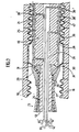
- channel 28 is illustrated in Figure 2 as a helical channel has a small cross-section in comparison with the cross-section of cooling channel 25 so that there is little danger of plastic extrudate being drawn into the suction channel 28 when suction is applied.
- the width of channel 28 may be as small as 0,25 mm (0.010 inches).
- Other shapes of channel are, of course, possible.
- Channel 28 communicates with a single source of suction (not shown or with a source of pressure (not shown) via branches 61, 62 of conduit 38 which opens into channel 28 at suction or pressure port 39.
- each channel 28 is located to apply suction downstream of the point at which cooling is started so that plastics material will not be drawn into channels 28.
- Equally channel 28 should be located such that pressure will cause the desired enlargement of the tube. This channel 28 must be located at a point where the tube is still sort enough to be formed.
- conduit 38 opens to channel 28 immediately downstream of the accumulator chamber.
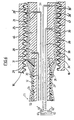
- Figure 1 shows the apparatus using suction
- Figure 5 shows the apparatus using pressure.
- Especially formed molds 16' of the traveling mold are provided for the formation of bells and the plastics material is forced thereinto under pneumatic pressure from channel 28.
- the apparatus of Figure 5 also differs from that of Figure 1 in that conduits 39 in Figure 1 are branches of conduit 38.
- conduits 39 in Figure 1 are branches of conduit 38.
- the pressure of either the vacuum or pneumatic pressure in the channels 28 of one end of the cooling plug 46 is not not independently adjustable in the apparatus illustrated in Figure 1.
- the channels 28' at the downstream end of plug 46 are, through conduit 39', independently connected to separate sources of vacuum or pneumatic pressure through respective branch conduits 61', 62'.
- upstream channels 28 connected through conduits 39 and 38 to branch conduits 61, 62 for application of vacuum or pneumatic pressure respectively.
- the Figure 5 apparatus allows independent regulation of either vacuum or pneumatic pressure at opposite ends of the cooling plug 46 and also makes it possible to apply vacuum at one end of cooling plug 46 and pneumatic pressure at the other end.
- Figure 5 illustrates the formation of a bell in annularly ribbed pipe and the application of vaccuum through channels 28, 28' when no bell is required, aiding the formation of a smooth inner wall of the resulting tube.
- Cooperating mold blocks 16' providing for molding a bell are provided in the endless mold block systems. When these mold blocks 16' are located as shown in Figure 5, vacuum applied through branch conduit 61 is turned off and pneumatic pressure is applied through branch conduit 62. Vacuum may suitably be retained in branch conduit 61' leading to channels 28' to aid in drawing the tube back to the outer surface of the cooling plug 46 when bell formation is no longer required.
- Figure 6 shows a similar apparatus to that of Figure 5 but the Figure 6 apparatus is for the formation of double walled corrugated tubing.
- Figure 6 shows the apparatus used with suction applied at both channels 28 and 28' resulting in a tube with smooth inner walls.
- the outer corrugated wall is formed from an outer plastic parison 70 extruded upstream of the inner extrudate 31 and biased into the mold in any suitable manner.
- channels 28 may have various forms to cover the surface of plug 46.
- channels 28 may comprise two interseting helical channels of opposite Twist.
- Figure 9 shows a modification in which pressure is applied from an upstream front end of the plug 46.
- bell formation of the inner parison may be prior to or at the point of entry into the channel between the mold and the plug 46.
- the inner parison will tend to balloon in an upstream direction to line bell 72. It is believed that certain advantages may derive from this embodiment.
Landscapes
- Engineering & Computer Science (AREA)
- Mechanical Engineering (AREA)
- Manufacturing & Machinery (AREA)
- Physics & Mathematics (AREA)
- Thermal Sciences (AREA)
- Extrusion Moulding Of Plastics Or The Like (AREA)
- Blow-Moulding Or Thermoforming Of Plastics Or The Like (AREA)
- Moulds For Moulding Plastics Or The Like (AREA)
- Rigid Pipes And Flexible Pipes (AREA)
Claims (4)
- Procédé de formage d'un tube en matière thermoplastique sans soudure comportant au moins une tulipe, comprenant les opérations consistant à extruder une préforme tubulaire de matière thermoplastique chauffée dans un moule-tunnel mobile, comprenant des séries de blocs de moulage articulés (16) adjacents, et à faire passer la préforme sur la surface extérieure du mandrin central (46) à l'intérieur du tube pour former un tube profilé; caractérisé en ce que des blocs de moulage (16') sont prévus pour mouler la surface externe de ladite tulipe, une pression pneumatique étant appliquée, par un certain nombre de canaux (39, 39') de communication de fluide dans le mandrin (46), sur une partie au moins de la surface extérieure de celui-ci voisine des blocs de moulage (16') formant la tulipe, et une aspiration étant appliquée par les canaux (39, 39') de communication de fluide lorsque des blocs de moulage (16) ne formant pas de tulipe sont voisins du tube.
- Procédé selon la revendication 1 pour le formage d'un tube à simple paroi.
- Procédé selon la revendication 1 pour le formage d'un tube ondulé à double paroi.
- Procédé selon la revendication 1, dans lequel la pression pneumatique est appliquée à une partie amont (28) du mandrin et l'aspiration est appliquée à une partie aval (28') du mandrin.
Applications Claiming Priority (3)
| Application Number | Priority Date | Filing Date | Title |
|---|---|---|---|
| CA599965 | 1989-05-17 | ||
| CA000599965A CA1329871C (fr) | 1989-05-17 | 1989-05-17 | Faconnage de tubes au moyen d'un poincon refroidisseur utilisant la pression d'aspiration et la pression d'air comprime |
| PCT/CA1990/000159 WO1990014208A1 (fr) | 1989-05-17 | 1990-05-16 | Procede de formage de tubes par l'application d'aspiration et de pression pneumatique a la surface du mandrin de refroidissement |
Publications (3)
| Publication Number | Publication Date |
|---|---|
| EP0483153A1 EP0483153A1 (fr) | 1992-05-06 |
| EP0483153B1 EP0483153B1 (fr) | 1994-08-31 |
| EP0483153B2 true EP0483153B2 (fr) | 1998-05-27 |
Family
ID=4140066
Family Applications (1)
| Application Number | Title | Priority Date | Filing Date |
|---|---|---|---|
| EP90906818A Expired - Lifetime EP0483153B2 (fr) | 1989-05-17 | 1990-05-16 | Procede de formage de tubes par l'application d'aspiration et de pression pneumatique a la surface du mandrin de refroidissement |
Country Status (7)
| Country | Link |
|---|---|
| EP (1) | EP0483153B2 (fr) |
| CN (1) | CN1023691C (fr) |
| AT (1) | ATE110623T1 (fr) |
| CA (1) | CA1329871C (fr) |
| DE (1) | DE69012129T3 (fr) |
| ES (1) | ES2061033T5 (fr) |
| WO (1) | WO1990014208A1 (fr) |
Families Citing this family (19)
| Publication number | Priority date | Publication date | Assignee | Title |
|---|---|---|---|---|
| DE4111229A1 (de) * | 1991-04-08 | 1992-10-15 | Wilhelm Hegler | Vorrichtung zur herstellung von kunststoff-rohren |
| DE4210482A1 (de) * | 1992-03-31 | 1993-10-07 | Wilhelm Hegler | Verfahren und Vorrichtung zur fortlaufenden Herstellung eines Verbundrohres mit Rohr-Muffe |
| CA2072663C (fr) * | 1992-06-29 | 1999-11-16 | Manfred A. A. Lupke | Methode et machine pour former des tubes thermoplastiques a double paroi et tulipes integrees |
| FI930826A0 (fi) * | 1993-02-24 | 1993-02-24 | Uponor Nv | Foerfarande och anordning foer att framstaella kamflaensar med sidoutbuktningar i plastroer och ett plastroer |
| US5531583A (en) * | 1993-04-15 | 1996-07-02 | Cullom Machine Tool & Die, Inc. | Vacuum mold blocks with cooling for corrugated tubing |
| WO1995001251A1 (fr) * | 1993-06-30 | 1995-01-12 | Lupke Manfred Arno Alfred | Procede et appareil permettant de former un tuyau thermoplastique a double paroi a emboitements integres |
| FR2718509B1 (fr) * | 1994-04-07 | 1996-08-30 | Courant Ets Sa | Procédé et dispositif pour la réalisation de tulipes sur des tubes annelés à deux parois. |
| DE19504501A1 (de) * | 1995-02-13 | 1996-08-14 | Wilhelm Hegler | Verfahren und Anlage zur Herstellung eines Mehrschicht-Rohres aus thermoplastischem Kunststoff, insbesondere Polyolefin |
| DE19841156C1 (de) * | 1998-09-09 | 1999-10-21 | Unicor Rohrsysteme Gmbh | Vorrichtung zur Herstellung von Rohren |
| DE10225582B4 (de) * | 2002-06-10 | 2016-10-27 | Manfred Arno Alfred Lupke | Verfahren und Vorrichtung zur Herstellung eines doppelwandigen Rohres aus thermoplastischem Kunststoff mit einer Rohrmuffe |
| FR2842753B1 (fr) * | 2002-07-26 | 2005-03-11 | Financ D Etudes Et De Dev Ind | Procede de realisation d'un outil destine au formage d'une matiere et outil susceptible d'etre realise par ce procede |
| DE102005029580B3 (de) * | 2005-06-25 | 2006-10-26 | Unicor Gmbh | Vorrichtung zur Herstellung von doppelwandigen Verbundrohren |
| DE102006018373A1 (de) * | 2006-04-20 | 2007-10-25 | Drossbach Gmbh & Co Kg | Vorrichtung zum Formen der Innenoberfläche eines Rohres aus thermoplastischem Material |
| KR101387304B1 (ko) * | 2007-07-13 | 2014-04-18 | 모레코르 테크놀로지아 에스.엘. | 분자구조상 바이-오리엔트된 플라스틱 파이프 제조 장치 및 그 방법 |
| RU2429967C1 (ru) * | 2007-07-13 | 2011-09-27 | Молекор Текнолохия С.Л. | Устройство и способ производства молекулярно биориентированных пластмассовых труб |
| DE102007050923A1 (de) * | 2007-10-23 | 2009-05-07 | Unicor Gmbh | Verfahren und Vorrichtung zur Herstellung eines doppelwandigen thermoplastischen Wellrohres mit einer Rohrmuffe |
| CN108274722B (zh) * | 2018-03-26 | 2023-11-21 | 大连三垒科技有限公司 | 波纹管双层承插口在线成型扩口模块尾部压紧装置 |
| CN110757854B (zh) * | 2019-11-01 | 2021-05-25 | 重庆市一龙管道有限公司 | Pe双壁波纹管加工设备 |
| WO2022169751A1 (fr) * | 2021-02-02 | 2022-08-11 | Essentium, Inc. | Filière d'extrusion comprenant un mandrin |
Citations (1)
| Publication number | Priority date | Publication date | Assignee | Title |
|---|---|---|---|---|
| US4808098A (en) † | 1988-03-16 | 1989-02-28 | Harry Chan | Pipe extrusion die with a cooled and vacuumed additional mandrel |
Family Cites Families (5)
| Publication number | Priority date | Publication date | Assignee | Title |
|---|---|---|---|---|
| NL6803115A (fr) * | 1968-03-05 | 1969-09-09 | ||
| US3743456A (en) * | 1971-08-20 | 1973-07-03 | Acme Hamilton Mfg Corp | Adjustable die heads for extruders and the like |
| AT343054B (de) * | 1973-10-16 | 1978-05-10 | Baar Heinz Joachim | Plastik-dranrohr und vorrichtung zur herstellung desselben |
| SE449456B (sv) * | 1983-11-15 | 1987-05-04 | Uponor Ab | Forfarande och anordning for framstellning av ror varvid formbacksdelarna er delade i formstreckans lengsriktning |
| DE3701822A1 (de) * | 1987-01-22 | 1988-08-11 | Uponor Nv | Verfahren und anordnung zum strangpressen von kunststoffrohren |
-
1989
- 1989-05-17 CA CA000599965A patent/CA1329871C/fr not_active Expired - Lifetime
-
1990
- 1990-05-16 CN CN90103567A patent/CN1023691C/zh not_active Expired - Fee Related
- 1990-05-16 ES ES90906818T patent/ES2061033T5/es not_active Expired - Lifetime
- 1990-05-16 EP EP90906818A patent/EP0483153B2/fr not_active Expired - Lifetime
- 1990-05-16 AT AT90906818T patent/ATE110623T1/de not_active IP Right Cessation
- 1990-05-16 DE DE69012129T patent/DE69012129T3/de not_active Expired - Fee Related
- 1990-05-16 WO PCT/CA1990/000159 patent/WO1990014208A1/fr not_active Ceased
Patent Citations (1)
| Publication number | Priority date | Publication date | Assignee | Title |
|---|---|---|---|---|
| US4808098A (en) † | 1988-03-16 | 1989-02-28 | Harry Chan | Pipe extrusion die with a cooled and vacuumed additional mandrel |
Also Published As
| Publication number | Publication date |
|---|---|
| ATE110623T1 (de) | 1994-09-15 |
| DE69012129D1 (de) | 1994-10-06 |
| ES2061033T5 (es) | 1998-09-16 |
| CN1023691C (zh) | 1994-02-09 |
| WO1990014208A1 (fr) | 1990-11-29 |
| DE69012129T2 (de) | 1995-02-23 |
| EP0483153A1 (fr) | 1992-05-06 |
| EP0483153B1 (fr) | 1994-08-31 |
| CA1329871C (fr) | 1994-05-31 |
| DE69012129T3 (de) | 2004-06-09 |
| ES2061033T3 (es) | 1994-12-01 |
| CN1047247A (zh) | 1990-11-28 |
Similar Documents
| Publication | Publication Date | Title |
|---|---|---|
| US5296188A (en) | Methods for forming tubing utilizing suction and pneumatic pressure at the surface of the cooling plug | |
| EP0483153B1 (fr) | Procede de formage de tubes par l'application d'aspiration et de pression pneumatique a la surface du mandrin de refroidissement | |
| CA1314676C (fr) | Filiere d'extrusion de tubes a mandrin additionnel refroidi et sous vide | |
| US4710337A (en) | Method and apparatus for continuously extruding single-wall pipe of plastics or other mouldable material | |
| US6705851B2 (en) | Extrusion molding apparatus for a thin tube | |
| CA1172813A (fr) | Dispositif pour la production de tubes multiparoi en matiere thermoplastique | |
| SU1598860A3 (ru) | Устройство дл экструзии пластмассовых труб | |
| CA1166415A (fr) | Moule composite pour la fabrication de tubes en matiere thermoplastique | |
| CN100526048C (zh) | 连续制造带管接头的复壁管的方法、复壁管和实施该方法和制造该复壁管的装置 | |
| EP0381938B1 (fr) | Mandrin de refroidissement dans un appareil à former des tuyaux thermoplastiques | |
| US4995800A (en) | Extrusion die assembly | |
| CN1007139B (zh) | 双层塑料管的挤压模 | |
| FI74654B (fi) | Anordning och foerfarande foer framstaellning av kamflaensroer. | |
| KR870008687A (ko) | 리브형 파이프 제조방법 및 그 장치 | |
| CA1320323E (fr) | Matrice d'extrusion pour tuyaux ayant des nervures | |
| US3309443A (en) | Plastic molding | |
| US2465482A (en) | Extruding apparatus | |
| US5186878A (en) | Improvements relating to cooling plugs in thermoplastic pipe forming apparatus and process | |
| JP2848550B2 (ja) | プラスチツク管に方向性を付与する装置及びこの装置により製造され方向性を付与されたリブ付きのプラスチツク管 | |
| US5023029A (en) | Method and apparatus for producing pipe with annular ribs | |
| US4936768A (en) | Extrusion die for externally ribbed plastic tubing | |
| WO1992022416A1 (fr) | Appareil de tunnel de moulage mobile permettant de produire des tuyaux a paroi lisse | |
| US3409941A (en) | Apparatus for producing plastic articles | |
| RU2153982C1 (ru) | Способ нанесения полимерного покрытия на металлическую трубу и устройство для его осуществления | |
| JPS6334011B2 (fr) |
Legal Events
| Date | Code | Title | Description |
|---|---|---|---|
| PUAI | Public reference made under article 153(3) epc to a published international application that has entered the european phase |
Free format text: ORIGINAL CODE: 0009012 |
|
| AK | Designated contracting states |
Kind code of ref document: A1 Designated state(s): AT BE CH DE DK ES FR GB IT LI LU NL SE |
|
| 17P | Request for examination filed |
Effective date: 19920326 |
|
| 17Q | First examination report despatched |
Effective date: 19931029 |
|
| RAP1 | Party data changed (applicant data changed or rights of an application transferred) |
Owner name: LUPKE, MANFRED ARNO ALFRED |
|
| GRAA | (expected) grant |
Free format text: ORIGINAL CODE: 0009210 |
|
| AK | Designated contracting states |
Kind code of ref document: B1 Designated state(s): AT BE CH DE DK ES FR GB IT LI LU NL SE |
|
| PG25 | Lapsed in a contracting state [announced via postgrant information from national office to epo] |
Ref country code: CH Effective date: 19940831 Ref country code: LI Effective date: 19940831 Ref country code: DK Effective date: 19940831 Ref country code: BE Effective date: 19940831 |
|
| REF | Corresponds to: |
Ref document number: 110623 Country of ref document: AT Date of ref document: 19940915 Kind code of ref document: T |
|
| REF | Corresponds to: |
Ref document number: 69012129 Country of ref document: DE Date of ref document: 19941006 |
|
| ITF | It: translation for a ep patent filed | ||
| ET | Fr: translation filed | ||
| REG | Reference to a national code |
Ref country code: ES Ref legal event code: FG2A Ref document number: 2061033 Country of ref document: ES Kind code of ref document: T3 |
|
| REG | Reference to a national code |
Ref country code: CH Ref legal event code: PL |
|
| EAL | Se: european patent in force in sweden |
Ref document number: 90906818.1 |
|
| PG25 | Lapsed in a contracting state [announced via postgrant information from national office to epo] |
Ref country code: LU Free format text: LAPSE BECAUSE OF NON-PAYMENT OF DUE FEES Effective date: 19950531 |
|
| PLBI | Opposition filed |
Free format text: ORIGINAL CODE: 0009260 |
|
| PLBI | Opposition filed |
Free format text: ORIGINAL CODE: 0009260 |
|
| 26 | Opposition filed |
Opponent name: HEGLER PLASTIK GMBH Effective date: 19950524 |
|
| 26 | Opposition filed |
Opponent name: HEGLER PLASTIK GMBH Effective date: 19950524 Opponent name: DROSSBACH GMBH & CO KG Effective date: 19950529 |
|
| NLR1 | Nl: opposition has been filed with the epo |
Opponent name: HEGLER PLASTIK GMBH |
|
| NLR1 | Nl: opposition has been filed with the epo |
Opponent name: HEGLER PLASTIK GMBH Opponent name: DROSSBACH GMBH & CO KG |
|
| PLAW | Interlocutory decision in opposition |
Free format text: ORIGINAL CODE: EPIDOS IDOP |
|
| PLAW | Interlocutory decision in opposition |
Free format text: ORIGINAL CODE: EPIDOS IDOP |
|
| PUAH | Patent maintained in amended form |
Free format text: ORIGINAL CODE: 0009272 |
|
| STAA | Information on the status of an ep patent application or granted ep patent |
Free format text: STATUS: PATENT MAINTAINED AS AMENDED |
|
| 27A | Patent maintained in amended form |
Effective date: 19980527 |
|
| AK | Designated contracting states |
Kind code of ref document: B2 Designated state(s): AT BE CH DE DK ES FR GB IT LI LU NL SE |
|
| REG | Reference to a national code |
Ref country code: CH Ref legal event code: AEN Free format text: AUFRECHTERHALTUNG DES PATENTES IN GEAENDERTER FORM |
|
| ITF | It: translation for a ep patent filed | ||
| NLR2 | Nl: decision of opposition | ||
| REG | Reference to a national code |
Ref country code: ES Ref legal event code: DC2A Kind code of ref document: T5 Effective date: 19980715 |
|
| ET3 | Fr: translation filed ** decision concerning opposition | ||
| NLR3 | Nl: receipt of modified translations in the netherlands language after an opposition procedure | ||
| REG | Reference to a national code |
Ref country code: GB Ref legal event code: IF02 |
|
| PGFP | Annual fee paid to national office [announced via postgrant information from national office to epo] |
Ref country code: SE Payment date: 20020502 Year of fee payment: 13 |
|
| PG25 | Lapsed in a contracting state [announced via postgrant information from national office to epo] |
Ref country code: SE Free format text: LAPSE BECAUSE OF NON-PAYMENT OF DUE FEES Effective date: 20030517 |
|
| EUG | Se: european patent has lapsed | ||
| PGFP | Annual fee paid to national office [announced via postgrant information from national office to epo] |
Ref country code: AT Payment date: 20070502 Year of fee payment: 18 |
|
| PGFP | Annual fee paid to national office [announced via postgrant information from national office to epo] |
Ref country code: NL Payment date: 20070524 Year of fee payment: 18 |
|
| PGFP | Annual fee paid to national office [announced via postgrant information from national office to epo] |
Ref country code: ES Payment date: 20070528 Year of fee payment: 18 |
|
| PGFP | Annual fee paid to national office [announced via postgrant information from national office to epo] |
Ref country code: DE Payment date: 20070702 Year of fee payment: 18 |
|
| PGFP | Annual fee paid to national office [announced via postgrant information from national office to epo] |
Ref country code: IT Payment date: 20070526 Year of fee payment: 18 |
|
| PGFP | Annual fee paid to national office [announced via postgrant information from national office to epo] |
Ref country code: FR Payment date: 20070517 Year of fee payment: 18 |
|
| PG25 | Lapsed in a contracting state [announced via postgrant information from national office to epo] |
Ref country code: NL Free format text: LAPSE BECAUSE OF NON-PAYMENT OF DUE FEES Effective date: 20081201 |
|
| PG25 | Lapsed in a contracting state [announced via postgrant information from national office to epo] |
Ref country code: AT Free format text: LAPSE BECAUSE OF NON-PAYMENT OF DUE FEES Effective date: 20080516 |
|
| REG | Reference to a national code |
Ref country code: FR Ref legal event code: ST Effective date: 20090119 |
|
| PG25 | Lapsed in a contracting state [announced via postgrant information from national office to epo] |
Ref country code: DE Free format text: LAPSE BECAUSE OF NON-PAYMENT OF DUE FEES Effective date: 20081202 Ref country code: FR Free format text: LAPSE BECAUSE OF NON-PAYMENT OF DUE FEES Effective date: 20080602 |
|
| REG | Reference to a national code |
Ref country code: ES Ref legal event code: FD2A Effective date: 20080517 |
|
| PG25 | Lapsed in a contracting state [announced via postgrant information from national office to epo] |
Ref country code: IT Free format text: LAPSE BECAUSE OF NON-PAYMENT OF DUE FEES Effective date: 20080516 |
|
| PG25 | Lapsed in a contracting state [announced via postgrant information from national office to epo] |
Ref country code: ES Free format text: LAPSE BECAUSE OF NON-PAYMENT OF DUE FEES Effective date: 20080517 |
|
| PGFP | Annual fee paid to national office [announced via postgrant information from national office to epo] |
Ref country code: GB Payment date: 20090528 Year of fee payment: 20 |
|
| PG25 | Lapsed in a contracting state [announced via postgrant information from national office to epo] |
Ref country code: GB Free format text: LAPSE BECAUSE OF EXPIRATION OF PROTECTION Effective date: 20100515 |