EP0483210B1 - Dichtung gegen umwelteinflüsse - Google Patents
Dichtung gegen umwelteinflüsse Download PDFInfo
- Publication number
- EP0483210B1 EP0483210B1 EP90910843A EP90910843A EP0483210B1 EP 0483210 B1 EP0483210 B1 EP 0483210B1 EP 90910843 A EP90910843 A EP 90910843A EP 90910843 A EP90910843 A EP 90910843A EP 0483210 B1 EP0483210 B1 EP 0483210B1
- Authority
- EP
- European Patent Office
- Prior art keywords
- sleeve
- heat
- substrates
- plug
- positioning
- Prior art date
- Legal status (The legal status is an assumption and is not a legal conclusion. Google has not performed a legal analysis and makes no representation as to the accuracy of the status listed.)
- Expired - Lifetime
Links
- 238000007789 sealing Methods 0.000 title description 7
- 230000007613 environmental effect Effects 0.000 title description 3
- 239000000758 substrate Substances 0.000 claims abstract description 43
- 238000000034 method Methods 0.000 claims abstract description 23
- 239000003566 sealing material Substances 0.000 claims abstract description 20
- 239000000565 sealant Substances 0.000 claims abstract description 9
- 239000002131 composite material Substances 0.000 claims description 4
- 239000000463 material Substances 0.000 claims description 4
- 230000000694 effects Effects 0.000 claims description 3
- 239000002390 adhesive tape Substances 0.000 claims 2
- 238000010438 heat treatment Methods 0.000 description 3
- 239000004831 Hot glue Substances 0.000 description 2
- 238000000926 separation method Methods 0.000 description 2
- 239000004698 Polyethylene Substances 0.000 description 1
- 241000220317 Rosa Species 0.000 description 1
- 230000004913 activation Effects 0.000 description 1
- 239000000853 adhesive Substances 0.000 description 1
- 230000001070 adhesive effect Effects 0.000 description 1
- 230000015572 biosynthetic process Effects 0.000 description 1
- 239000011248 coating agent Substances 0.000 description 1
- 238000000576 coating method Methods 0.000 description 1
- 238000005260 corrosion Methods 0.000 description 1
- 230000007797 corrosion Effects 0.000 description 1
- 210000005069 ears Anatomy 0.000 description 1
- 238000005538 encapsulation Methods 0.000 description 1
- 230000001747 exhibiting effect Effects 0.000 description 1
- 239000004744 fabric Substances 0.000 description 1
- 239000011521 glass Substances 0.000 description 1
- 239000002654 heat shrinkable material Substances 0.000 description 1
- 238000009434 installation Methods 0.000 description 1
- 238000009413 insulation Methods 0.000 description 1
- 238000002844 melting Methods 0.000 description 1
- 230000008018 melting Effects 0.000 description 1
- 239000004033 plastic Substances 0.000 description 1
- 229920003023 plastic Polymers 0.000 description 1
- -1 polyethylene Polymers 0.000 description 1
- 229920000573 polyethylene Polymers 0.000 description 1
- 238000011084 recovery Methods 0.000 description 1
- 230000000717 retained effect Effects 0.000 description 1
- 230000007704 transition Effects 0.000 description 1
- 239000002759 woven fabric Substances 0.000 description 1
Images
Classifications
-
- H—ELECTRICITY
- H02—GENERATION; CONVERSION OR DISTRIBUTION OF ELECTRIC POWER
- H02G—INSTALLATION OF ELECTRIC CABLES OR LINES, OR OF COMBINED OPTICAL AND ELECTRIC CABLES OR LINES
- H02G15/00—Cable fittings
- H02G15/013—Sealing means for cable inlets
-
- H—ELECTRICITY
- H02—GENERATION; CONVERSION OR DISTRIBUTION OF ELECTRIC POWER
- H02G—INSTALLATION OF ELECTRIC CABLES OR LINES, OR OF COMBINED OPTICAL AND ELECTRIC CABLES OR LINES
- H02G15/00—Cable fittings
- H02G15/08—Cable junctions
- H02G15/18—Cable junctions protected by sleeves, e.g. for communication cable
-
- B—PERFORMING OPERATIONS; TRANSPORTING
- B29—WORKING OF PLASTICS; WORKING OF SUBSTANCES IN A PLASTIC STATE IN GENERAL
- B29C—SHAPING OR JOINING OF PLASTICS; SHAPING OF MATERIAL IN A PLASTIC STATE, NOT OTHERWISE PROVIDED FOR; AFTER-TREATMENT OF THE SHAPED PRODUCTS, e.g. REPAIRING
- B29C61/00—Shaping by liberation of internal stresses; Making preforms having internal stresses; Apparatus therefor
- B29C61/06—Making preforms having internal stresses, e.g. plastic memory
- B29C61/0608—Making preforms having internal stresses, e.g. plastic memory characterised by the configuration or structure of the preforms
- B29C61/0641—Clips for dividing preforms or forming branch-offs
-
- Y—GENERAL TAGGING OF NEW TECHNOLOGICAL DEVELOPMENTS; GENERAL TAGGING OF CROSS-SECTIONAL TECHNOLOGIES SPANNING OVER SEVERAL SECTIONS OF THE IPC; TECHNICAL SUBJECTS COVERED BY FORMER USPC CROSS-REFERENCE ART COLLECTIONS [XRACs] AND DIGESTS
- Y10—TECHNICAL SUBJECTS COVERED BY FORMER USPC
- Y10S—TECHNICAL SUBJECTS COVERED BY FORMER USPC CROSS-REFERENCE ART COLLECTIONS [XRACs] AND DIGESTS
- Y10S174/00—Electricity: conductors and insulators
- Y10S174/08—Shrinkable tubes
Definitions
- This invention relates to environmental sealing, particularly by means of a heat-shrinkable sleeve of substrates, such as telecommunications or other cables, particularly at cable splices or other regions where cables run close to one another, especially spaced apart by a fixed amount.
- Heat-shrinkable articles are now widely used in many areas where environmental sealing, for example, insulation, bonding or encapsulation, is required. Usually these articles dimensionally-recover on heating to a shape from which they have previously been deformed, but the term "heat-shrinkable” as used herein also includes an article which, on heating, adopts a new configuration, even if it has not previously been deformed.
- such articles comprise heat-shrinkable sleeves made from polymeric material exhibiting the property of elastic or plastic memory as desired, for example, in US 2027962, 3086242 and 3957382.
- Heat-shrinkable sleeves find many applications, especially in the connection and termination of wires, cables and pipes. However, there are applications where it is desirable to provide a sealing member for elongate substrates such as cables or pipes or other supply lines whose ends are not accessible. For such applications so-called "wrap-around" sleeeves have been developed. Basically, they are heat-shrinkable sheets which can be wrapped around a substrate to form a generally tubular shape and which, in general, are provided with fastening means for holding them in the wrapped-around configuration during heat-shrinkage. Examples of such sleeves are disclosed in GB1155470.
- Heat-shrinkable sleeves have been successfully employed in many fields, but problems may arise when two or more substrates have to be sealed at one position. This problem, which is known as "branch-off", may occur, for example, at the outlet of a heat-shrinkable part. Amongst fields in which this problem is typically encountered there may especially be mentioned the outlets of the splice cases described and claimed in GB1431167 (Raychem).
- US 4400579 discloses and claims an assembly comprising a heat-shrinkable sleeve capable of being positioned around at least first and second elongate substrates, and a clip formed as a trident, the outer legs of which are capable of being positioned over the outer surface of the sleeve at the end thereof with the central leg of the trident (which may taper towards its proximal end and may be coated with an adhesive) inside the sleeve so as to form, and maintain during subsequent heat shrinkage of the sleeve, at least two terminal conduits respectively capable of receiving the first and second substrates.
- GB 2019114 discloses and claims a kit of parts comprising a heat-shrinkable sleeve and at least one fork member for use in forming a seal between the sleeve and at least two substrates by a method which comprises threading an end portion of the sleeve, which is positioned between the two substrates about the prongs of the fork member so that, on recovery, the heat shrinkable material tightens within the prongs of said fork member and at least two of the prongs of the fork member abut the outer surfaces of the sleeve surrounding the substrate so as to retain the fork member firmly in position, the fork member being retained with lateral ears that in use may rest against substrates where they pass out of the sleeve.
- a tubular clip having longitudinally-extending, circumferentially-separated slits is disclosed in EP 0094793 (Raychem). The intention there is to hold together two thicknesses of a heat-shrinkable sleeve between two spaced apart substrates.
- EP 0050995 discloses the use of two or more clips (one of which may be a heat-pipe) to seal a heat-shrinkable sleeve around three or more cables, and also to DE 2413623 (Rose) and DE 3243446 (Siemens) which disclose the formation of conduits by positioning of cylindrical plugs within heat-shrinkable sleeves.
- the invention provides a method of forming a branch-off seal between a heat-shrinkable sleeve and at least two spaced-apart elongate substrates, which comprises the steps of:
- a sleeve is first installed around the substrates, preferably by wrapping it around them and securing it in the wrapped-around configuration.
- the plug and sealant are placed within the sleeve between the substrates, placing of plug and sealant preferably occuring simultaneously since the plug preferably includes the sealant especially as a tape wrap around a support member.
- two clips are installed, respective clips being positioned between the plug and a respective substrate.
- Heat is then applied, for example, by an open-flame torch or a hot-air gun or by electrical heating means that may be part of the sleeve, to cause the sleeve to shrink and the sealant to become heat-activated, preferably by melting or otherwise softening.
- the plug and sealant may be positioned between the substrates and held in place by wedging or tape wrapping etc before positioning of the sleeve.
- the clips may be two-legged clips of simple U-shape, each leg of the U being positioned externally of the sleeve to bring circumferentially-spaced portions of the sleeve together and/or to maintain such portions together (for example, where the sleeve is pre-shaped) during heat-shrinkage, and optionally also during service life of the product.
- Preferred clips comprise three legs, preferably lying in a common plane, a middle leg of the clip comprising a sealing material, preferably a hot-melt adhesive, and more particularly comprising a heat-conductive support coated with a sealing material.
- Such a clip is positioned with its outer legs externally of the sleeve and its middle leg internally of the sleeve between the substrates. In this way sealing material is delivered by the clip to a space that may otherwise remain between the substrates and the sleeve.
- the middle leg comprises a heat-conductive support and a sealing material
- heat may be conducted during installation from a torch etc via the outer legs to the middle leg to activate the sealing material thereon.
- the plug may have any suitable shape so long as one end has a larger cross-sectional size than the other end, these ends being defined in the method of the invention in terms of their position relative to the sleeve when the plug is installed in the sleeve.
- the plug be elongate and positioned substantially parallel to the substrates.
- the plug (or a support member thereof) is of substantially uniform cross-sectional shape along its length, and also is preferably of substantially circular or substantially oval cross-section.
- the plug (or a support member thereof) comprises first and second substantially cylindrical portions interconnected by a substantially frusto-conical portion, the first portion being of larger cross-sectional size than the second portion.
- the second portion is from 0.75 - 2.0, preferably 1.0 - 1.75 times the length of the first portion, and that the frusto-conical portion (where present) is from 0.2 - 1.0, preferably 0.2 - 0.5 times the length of the first portion.
- the first portion preferably has a cross-sectional size in the direction from one substrate to the other of from 0.5 - 0.95, more preferably 0.6 - 0.9 times the separation between the substrates.
- the plug may be built up in length and/or cross-section in a modular fashion to adapt it to different sizes of substrate.
- an adaptor of annular shape comprising for example a sealing material, may be installed around the first portion to increase its cross-sectional size.
- the plug preferably has a length such that the first portion touches or almost touches (say, is within 2 or 3 cms) of the splice or splice case that joins or seals the two cables and the second portion extends to a position from 3 cms short of to 3 cms proud of the end of the sleeve.
- the heat-shrinkable sleeve may, for example, comprise a uniform extruded polymeric material or a composite material, preferably one comprising a fibre-reinforced polymeric material.
- the fibres may be present as a fabric, especially a woven fabric and may comprise heat-shrinkable and/or heat-stable fibres.
- the sleeve has circumferentially-extending heat-recoverable fibres and longitudinally-extending heat-stable fibres, preferably comprising polyethylene and glass respectively.
- Such a composite material is disclosed and claimed in EP 0116393 (Raychem).
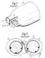
- the prior art clip 1 of figure 1 has two outer legs 2 and a middle leg, and is positioned at an end of a heat-shrinkable sleeve 4 to form two terminal conduits 5.
- the clip causes deformation of the sleeve (which in the absence of the clip had a single, larger, terminal conduit) to bring together circumferentially-spaced portions thereof at a position 6.
- This design is disclosed in US 4400579, mentioned above.
- FIG. 2 is a transverse cross-section at the end of a shrinkable sleeve 4 surrounding two multi-core telecommunications cables 7.
- the sleeve is a wrap-around sleeve, held in the wrapped-around configuration by a closure means 8.
- the clip or fork here has only two legs and opposing portions of the sleeve 4 at position 6 between fixed space-apart cables 7 are threaded through the legs, or prongs, of the clip 1. The two portions of the sleeve are thus held in contact with one another over a significant length 6.
- the sleeve is, of course, shown before shrinkage. This design is disclosed in GB 2019114, mentioned above.
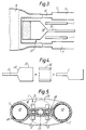
- FIG 3 is a plan view of an end of a cable splice case, showing positioning of two branch-off clips and a plug, as used in the invention, but the heat-shrinkable sleeve is omitted for clarity.
- Two cables 7 are spliced in a splice case 9, for example a lead splice in which the outlets 10 of the splice are spaced apart by a fixed distance.
- the incoming cables 7 are surrounded by one or more cable jackets 11. It is often desirable that the region of the lead splice shown surrounded by a dotted line be environmentally protected by a sealing material in addition to being surrounded by a sleeve.
- a plug 12 is provided between the cables and within the sleeve.
- the plug 12 is provided between the cables and within the sleeve.
- the plug 12 comprises a first portion 13 of larger cross-sectional size connected by a frusto-conical portion 14 to a second portion 15 of smaller cross-sectional size, the frusto-conical portion tapering towards the second portion.
- the base of the frusto-conical portion is the same size and shape as those of the first portion, and its top is the same size and shape as those of the second portion so a smooth transition between first and second portions is provided.
- the first portion comprises a sealing material, such as a hot-melt adhesive, which is shown by stippling. If desired, the sealing material may be supplied separately, for example by wrapping it around the cable outlets 10.
- the plug may comprise a support member, coated with a sealing material. The support member may be heat-conductive to aid activation of the sealing material. It is believed that the plug may serve to deliver the sealing material to the desired location and may act as a dam, as well as reducing the amount of sealing material required.
- Figure 4 shows a modular plug in which a part 16 can be added to the part labelled 13, 14, 15 to increase the diameter of its first portion 13.
- the part 16 may comprise an annulus of sealing material.
- Figure 5 shows an end view of a splice case, which would correspond to the view 17 of the prior art splice case of figure 1.
- two clips 1 are used, on each side of the plug, whose second portion 15 can be seen.
- the dotted line 19 shows the position of the first portion of the plug that is hidden within the sleeve 4.
- Any gaps between the cables and the sleeve etc may be filled by a sealing material 18, for example from an internal coating of the sleeve, from a middle leg 3 of the clips 1, and/or from the plug.
- a single clip may be used, for example incorporating two structures similar to the two clips illustrated.
Landscapes
- Cable Accessories (AREA)
- Glass Compositions (AREA)
- Infusion, Injection, And Reservoir Apparatuses (AREA)
- Insulating Bodies (AREA)
- Lining Or Joining Of Plastics Or The Like (AREA)
- Shaping By String And By Release Of Stress In Plastics And The Like (AREA)
- Liquid Crystal (AREA)
- Piezo-Electric Or Mechanical Vibrators, Or Delay Or Filter Circuits (AREA)
- Sealing Material Composition (AREA)
Claims (12)
- Verfahren, um eine Abzweigabdichtung zwischen einer wärmeschrumpfbaren Hülle und mindestens zwei voneinander beabstandeten langgestreckten Substraten zu bilden, wobei das Verfahren die folgenden Schritte aufweist:(a) Positionieren der Substrate innerhalb der wärmeschrumpfbaren Hülle;(b) Positionieren eines Stopfens zwischen den Substraten und innerhalb der Hülle an einem offenen Ende von dieser, wobei der Stopfen an einer ersten Position, entfernt von dem offenen Ende eine größere Querschnittsgröße und an einer zweiten Position in Richtung zu dem offenen Ende hin eine kleinere Querschnittsgröße hat;(c) Positionieren eines durch Wärme aktivierbaren Abdichtmaterials an der ersten Position;(d) Bilden und/oder Festhalten von mindestens drei wärmeschrumpfbaren Leitungen in der Hülle durch Positionieren von einem oder mehreren Clips an dem offenen Ende der Hülle, derart, daß sich die Substrate und der Stopfen in jeweiligen Leitungen befinden; und(e) während der Clip auf der Hülle verbleibt, Aufbringen von Wärme, um ein Schrumpfen der Hülle zu bewirken, um das Abdichtmaterial zu aktivieren und die gewünschte Abdichtung zu bilden.
- Verfahren nach Anspruch 1,
bei dem der Stopfen ein Abstützelement aufweist, um das zumindest an der ersten Position ein Klebeband herumgewickelt wird, wobei das Klebeband zumindest einen Teil des Abdichtmaterials bildet. - Verfahren nach Anspruch 1 oder 2,
bei dem drei Leitungen durch ein Verfahren gebildet werden, welches das Positionieren von mindestens zwei Clips, die jeweils mindestens zwei langgestreckte Schenkel haben, an dem offenen Ende der Hülle umfaßt, wobei die jeweiligen Clips zwischen dem Stopfen und einem jeweiligen Substrat positioniert werden und wobei mindestens zwei Schenkel jedes Clips außerhalb der Hülle positioniert werden. - Verfahren nach Anspruch 3,
bei dem jeder der Clips mindestens drei Schenkel hat, zumindest der eine Schenkel ein durch Wärme aktivierbares Abdichtmaterial aufweist und zumindest der eine Schenkel im Inneren der Hülle positioniert wird. - Verfahren nach einem der vorhergehenden Ansprüche,
bei dem der Stopfen oder ein Abstützelement davon eine im wesentlichen einheitliche Querschnittsform entlang einer Länge davon hat. - Verfahren nach einem der vorhergehenden Ansprüche,
bei dem der Stopfen oder ein Abstützelement davon im wesentlichen kreisförmigen oder im wesentlichen ovalen Querschnitt hat. - Verfahren nach einem der vorhergehenden Ansprüche,
bei dem der Stopfen oder ein Abstützelement davon erste und zweite im wesentlichen zylindrische Bereiche aufweisen, die durch einen im wesentlichen kegelstumpfförmigen Bereich, der sich in Richtung zu dem zweiten Bereich verjüngt, miteinander verbunden sind, wobei der erste Bereich eine größere Querschnittsgröße als der zweite Bereich hat. - Verfahren nach einem der vorhergehenden Ansprüche,
bei dem die Hülle ein Verbundmaterial aufweist. - Verfahren nach Anspruch 8,
bei dem das Verbundmaterial ein faserverstärktes polymeres Material aufweist. - Verfahren nach einem der vorhergehenden Ansprüche,
bei dem die Substrate mit einem festen Abstand voneinander beabstandet sind. - Verfahren nach einem der vorhergehenden Ansprüche,
bei dem die Substrate Kabel aufweisen. - Verfahren nach Anspruch 11,
bei dem die Substrate einen Bleikabelspleiß aufweisen.
Applications Claiming Priority (3)
| Application Number | Priority Date | Filing Date | Title |
|---|---|---|---|
| GB898916590A GB8916590D0 (en) | 1989-07-20 | 1989-07-20 | Environmental sealing |
| GB8916590 | 1989-07-20 | ||
| PCT/GB1990/001098 WO1991001581A1 (en) | 1989-07-20 | 1990-07-17 | Environmental sealing |
Publications (2)
| Publication Number | Publication Date |
|---|---|
| EP0483210A1 EP0483210A1 (de) | 1992-05-06 |
| EP0483210B1 true EP0483210B1 (de) | 1995-01-25 |
Family
ID=10660327
Family Applications (1)
| Application Number | Title | Priority Date | Filing Date |
|---|---|---|---|
| EP90910843A Expired - Lifetime EP0483210B1 (de) | 1989-07-20 | 1990-07-17 | Dichtung gegen umwelteinflüsse |
Country Status (9)
| Country | Link |
|---|---|
| US (1) | US5278355A (de) |
| EP (1) | EP0483210B1 (de) |
| JP (1) | JPH04507039A (de) |
| KR (1) | KR920704392A (de) |
| AT (1) | ATE117851T1 (de) |
| CA (1) | CA2063429A1 (de) |
| DE (1) | DE69016431D1 (de) |
| GB (1) | GB8916590D0 (de) |
| WO (1) | WO1991001581A1 (de) |
Families Citing this family (3)
| Publication number | Priority date | Publication date | Assignee | Title |
|---|---|---|---|---|
| GB9203943D0 (en) * | 1992-02-25 | 1992-04-08 | Raychem Sa Nv | Cable seal |
| FR2692385B1 (fr) * | 1992-06-16 | 1999-12-31 | Gemplus Card Int | Systeme automatique d'impression d'un formulaire administratif medical. |
| ATE149271T1 (de) * | 1992-12-08 | 1997-03-15 | Rxs Schrumpftech Garnituren | Verfahren zum herstellen eines dichten abschlusses an den enden einer schrumpfbaren kabelmuffe und abdichtelement hierfür |
Family Cites Families (11)
| Publication number | Priority date | Publication date | Assignee | Title |
|---|---|---|---|---|
| DE2413623C3 (de) * | 1974-03-21 | 1984-08-02 | Walter Rose Gmbh & Co Kg, 5800 Hagen | Flüssigkeitsdichte, eingangsseitige Abdichtung von mindestens zwei in ein Muffengehäuse parallel einmündenden Kabeln |
| GB1604981A (en) * | 1978-01-09 | 1981-12-16 | Raychem Sa Nv | Branchoff method |
| US4400579A (en) * | 1978-01-09 | 1983-08-23 | N.V. Raychem S.A. | Branch-off assembly |
| DE3243446A1 (de) * | 1982-11-24 | 1984-05-24 | Siemens AG, 1000 Berlin und 8000 München | Kabelmuffe mit fuellstueck aus schrumpfbarem material im einfuehrungsbereich |
| DE3341661A1 (de) * | 1983-02-03 | 1984-08-09 | Veb Kombinat Medizin- Und Labortechnik Leipzig, Ddr 7035 Leipzig | Schwebekoerper-durchflussmesser mit signalgeber |
| GB8305311D0 (en) * | 1983-02-25 | 1983-03-30 | Raychem Sa Nv | Cable branch-off |
| GB8314651D0 (en) * | 1983-05-26 | 1983-06-29 | Raychem Sa Nv | Electrically heat-recoverable article |
| DE3341618A1 (de) * | 1983-11-17 | 1985-05-30 | Siemens AG, 1000 Berlin und 8000 München | Stirnseitige abdichtung einer schrumpfbaren kabelgarnitur |
| ES8609835A1 (es) * | 1984-01-10 | 1986-07-16 | Raychem Sa Nv | Procedimiento para asegurar la estanqueidad en una bifurcacion entre un manguito y por lo menos dos substratos |
| NZ222263A (en) * | 1986-10-24 | 1990-10-26 | Fujikura Ltd | Heat-conducting insert melts block to seal cable branch junction |
| GB8824655D0 (en) * | 1988-10-21 | 1988-11-30 | Alh Syst Ltd | Sealing cable junctions |
-
1989
- 1989-07-20 GB GB898916590A patent/GB8916590D0/en active Pending
-
1990
- 1990-07-17 WO PCT/GB1990/001098 patent/WO1991001581A1/en not_active Ceased
- 1990-07-17 JP JP2510030A patent/JPH04507039A/ja active Pending
- 1990-07-17 US US07/820,598 patent/US5278355A/en not_active Expired - Fee Related
- 1990-07-17 DE DE69016431T patent/DE69016431D1/de not_active Expired - Lifetime
- 1990-07-17 KR KR1019920700108A patent/KR920704392A/ko not_active Abandoned
- 1990-07-17 AT AT90910843T patent/ATE117851T1/de not_active IP Right Cessation
- 1990-07-17 EP EP90910843A patent/EP0483210B1/de not_active Expired - Lifetime
- 1990-07-17 CA CA002063429A patent/CA2063429A1/en not_active Abandoned
Also Published As
| Publication number | Publication date |
|---|---|
| WO1991001581A1 (en) | 1991-02-07 |
| JPH04507039A (ja) | 1992-12-03 |
| ATE117851T1 (de) | 1995-02-15 |
| GB8916590D0 (en) | 1989-09-06 |
| US5278355A (en) | 1994-01-11 |
| DE69016431D1 (de) | 1995-03-09 |
| KR920704392A (ko) | 1992-12-19 |
| CA2063429A1 (en) | 1991-01-21 |
| EP0483210A1 (de) | 1992-05-06 |
Similar Documents
| Publication | Publication Date | Title |
|---|---|---|
| US4734543A (en) | Branch-off assembly | |
| US4400579A (en) | Branch-off assembly | |
| CA1232347A (en) | Cable joint enclosure | |
| US4409426A (en) | Splice case | |
| EP0094793B1 (de) | Verzweigung | |
| GB2119586A (en) | Cable joint protection | |
| US5278355A (en) | Environmental sealing | |
| US5451278A (en) | Environmental protection | |
| EP0120603B1 (de) | Kabelabzweigung und Verfahren zu deren Herstellung | |
| GB1604985A (en) | Branchoff method | |
| WO1994023471A1 (en) | Sealing ground wires using heat shrinkable sleeves | |
| CA1156817A (en) | Clip for use in forming a branch-off seal | |
| EP0475970B1 (de) | Gegen umwelteinflüsse geschützte dichtung | |
| CA1177627A (en) | Branch-off method | |
| CA1286485C (en) | Branch-off clip | |
| EP0551723A1 (de) | Artikel zum Abdichten des Endbereiches einer wärmegeschrumpften Manschette | |
| WO1990010331A1 (en) | Cable splice protection | |
| WO1995015602A1 (en) | Environmental seal | |
| GB2107939A (en) | Heat-recoverable articles | |
| WO1992012843A1 (en) | Branch-off seal | |
| HK20482A (en) | Branch-off method | |
| WO1992012842A1 (en) | Cable branch-off seal | |
| NZ236746A (en) | Heat shrinkable sleeve holding clip on slideway interposed between sleeve and cable |
Legal Events
| Date | Code | Title | Description |
|---|---|---|---|
| PUAI | Public reference made under article 153(3) epc to a published international application that has entered the european phase |
Free format text: ORIGINAL CODE: 0009012 |
|
| 17P | Request for examination filed |
Effective date: 19911210 |
|
| AK | Designated contracting states |
Kind code of ref document: A1 Designated state(s): AT BE CH DE DK ES FR GB IT LI NL SE |
|
| 17Q | First examination report despatched |
Effective date: 19940214 |
|
| GRAA | (expected) grant |
Free format text: ORIGINAL CODE: 0009210 |
|
| AK | Designated contracting states |
Kind code of ref document: B1 Designated state(s): AT BE CH DE DK ES FR GB IT LI NL SE |
|
| PG25 | Lapsed in a contracting state [announced via postgrant information from national office to epo] |
Ref country code: CH Effective date: 19950125 Ref country code: DK Effective date: 19950125 Ref country code: FR Effective date: 19950125 Ref country code: ES Free format text: THE PATENT HAS BEEN ANNULLED BY A DECISION OF A NATIONAL AUTHORITY Effective date: 19950125 Ref country code: LI Effective date: 19950125 Ref country code: AT Effective date: 19950125 Ref country code: IT Free format text: LAPSE BECAUSE OF FAILURE TO SUBMIT A TRANSLATION OF THE DESCRIPTION OR TO PAY THE FEE WITHIN THE PRE;WARNING: LAPSES OF ITALIAN PATENTS WITH EFFECTIVE DATE BEFORE 2007 MAY HAVE OCCURRED AT ANY TIME BEFORE 2007. THE CORRECT EFFECTIVE DATE MAY BE DIFFERENT FROM THE ONE RECORDED.SCRIBED TIME-LIMIT Effective date: 19950125 |
|
| REF | Corresponds to: |
Ref document number: 117851 Country of ref document: AT Date of ref document: 19950215 Kind code of ref document: T |
|
| REF | Corresponds to: |
Ref document number: 69016431 Country of ref document: DE Date of ref document: 19950309 |
|
| PG25 | Lapsed in a contracting state [announced via postgrant information from national office to epo] |
Ref country code: SE Effective date: 19950425 |
|
| PG25 | Lapsed in a contracting state [announced via postgrant information from national office to epo] |
Ref country code: DE Effective date: 19950426 |
|
| REG | Reference to a national code |
Ref country code: CH Ref legal event code: PL |
|
| EN | Fr: translation not filed | ||
| PG25 | Lapsed in a contracting state [announced via postgrant information from national office to epo] |
Ref country code: GB Effective date: 19950717 |
|
| PLBE | No opposition filed within time limit |
Free format text: ORIGINAL CODE: 0009261 |
|
| STAA | Information on the status of an ep patent application or granted ep patent |
Free format text: STATUS: NO OPPOSITION FILED WITHIN TIME LIMIT |
|
| 26N | No opposition filed | ||
| GBPC | Gb: european patent ceased through non-payment of renewal fee |
Effective date: 19950717 |
|
| PGFP | Annual fee paid to national office [announced via postgrant information from national office to epo] |
Ref country code: NL Payment date: 19970731 Year of fee payment: 8 |
|
| PGFP | Annual fee paid to national office [announced via postgrant information from national office to epo] |
Ref country code: BE Payment date: 19970911 Year of fee payment: 8 |
|
| PG25 | Lapsed in a contracting state [announced via postgrant information from national office to epo] |
Ref country code: BE Free format text: LAPSE BECAUSE OF NON-PAYMENT OF DUE FEES Effective date: 19980731 |
|
| BERE | Be: lapsed |
Owner name: RAYCHEM LTD Effective date: 19980731 |
|
| PG25 | Lapsed in a contracting state [announced via postgrant information from national office to epo] |
Ref country code: NL Free format text: LAPSE BECAUSE OF NON-PAYMENT OF DUE FEES Effective date: 19990201 |
|
| NLV4 | Nl: lapsed or anulled due to non-payment of the annual fee |
Effective date: 19990201 |