EP0483359A1 - Produktionssystem - Google Patents
Produktionssystem Download PDFInfo
- Publication number
- EP0483359A1 EP0483359A1 EP91905903A EP91905903A EP0483359A1 EP 0483359 A1 EP0483359 A1 EP 0483359A1 EP 91905903 A EP91905903 A EP 91905903A EP 91905903 A EP91905903 A EP 91905903A EP 0483359 A1 EP0483359 A1 EP 0483359A1
- Authority
- EP
- European Patent Office
- Prior art keywords
- control
- cluster
- control expression
- rules
- rule
- Prior art date
- Legal status (The legal status is an assumption and is not a legal conclusion. Google has not performed a legal analysis and makes no representation as to the accuracy of the status listed.)
- Withdrawn
Links
Images












Classifications
-
- G—PHYSICS
- G06—COMPUTING OR CALCULATING; COUNTING
- G06N—COMPUTING ARRANGEMENTS BASED ON SPECIFIC COMPUTATIONAL MODELS
- G06N5/00—Computing arrangements using knowledge-based models
- G06N5/04—Inference or reasoning models
- G06N5/046—Forward inferencing; Production systems
Definitions
- the present invention relates to a production system and, more particularly, to a method for integrating flow descriptions in a procedural language and production rules to thereby simplify programming and a method for converting the said program into a form executable in conventional production systems.
- a knowledge expressed by a form "IF A THEN B" is called a production rule (hereinafter referred to simply as a rule), and A is called a condition part and B an action part.
- the condition part and the action part are related to each other for solving a problem in a given application domain based on an expert's knowledge.
- Fig. 15 is a conceptual diagram of a production system which make inferences on a set of rules and performs knowledge processing.
- the reference numeral 1 indicates a production memory for storing a plurality of the said rules and 2 a working memory for storing a plurality of working memory elements each composed of a class name and a plurality of attribute values.
- An inference unit 3 matches the condition parts of all the rules with all of the working memory elements, instantiates and groups those of the rules whose conditions are all satisfied into a conflict set 4, selects one of the rules based on a certain strategy and executes an operation described in the action part of the rule thus selected.
- Such execution of the action part of a rule is called firing of the rule and the firing usually causes a change in the contents of the working memory, but the conflict set is produced and the inference processing is repeatedly performed regardless of whether or not the contents of the working memory undergo a change.
- Fig. 16 is a flowchart of the above-mentioned operation, consisting of steps 1 through 3.
- Step 1 Matching
- Step 2 Resolution of conflict
- Step 3 Execution
- Execution of the selected rule and updating of data The production system obtains a desired result usually by repeatedly performing the above-mentioned steps 1 through 3 while at the same time updating the working memory elements; when no rule satisfying all the conditions after "IF" is found or the action part after "THEN"contains a description stopping the process, however, the production system terminates the process regardless of the result.
- condition part of a rule often contains a combination of plural conditions (hereinafter each referred to as a condition element, but a programmer needs only to list up such condition elements in the condition part.
- action part he only needs to write actions to be executed corresponding to the condition elements in the condition part in the order of their execution.
- the reason for this is that the execution sequence of the rules is automatically determined based on an expert knowledge contained in each of the rules, and the selection of one of the rules out of the conflict set is based on a predetermined strategy, for example, the rule having the largest number of condition elements is selected first.
- the rules need not be arranged in any predetermined sequence but may be arbitrarily unsequenced.
- This condition element means "If there exists a working memory element which has the class name 'Control' and a value 'Cluster A' of the attribute ⁇ now." Incidentally, only one control working memory element is employed for cluster control, and upon completion of each processing in a certain cluster, the attribute value of the control working memory element is updated or changed to the cluster name to be invoked next. Thus, different clusters are selected one after another.
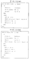
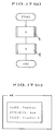
- Fig. 17(a) is a flowchart for executing subtasks A and B in this order and Fig. 17(b) shows rules corresponding thereto.
- reference numerals 5 and 6 indicate the subtasks A and B
- rule names Ar1 to Arn denote rules belonging to a cluster A and Br1 to Brm rules belonging to a cluster B.
- the rule Ar1 begins with "DEFINE RULE Ar1", identifying the rule name followed by descriptions of a condition part 7 and an action part 8, ending with an "END".
- the action part 8 starts with "THEN”, followed by a group of actions Ar1 denoting a plurality of actions in general form, terminating with "END". Other rules are also described in the same fashion as mentioned above.
- action 9 which is fired at the end of the execution of the subtask A
- action 10 which changes the value of the attribute " ⁇ now” of the control working memory element to "Cluster B”
- action 10 “STOP” described in the action part of the rule Brm which is fired at the end of the execution of the subtask B.
- the numeral immediately following “MODIFY”, "1” in this example indicates the line number of the condition element with which the working memory element updated should match. This method permits omission of the class name of the working memory element whose attribute value is to be updated.
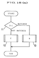
- Fig. 18(a) is a flowchart including a branch and Fig. 18(b) rules corresponding thereto.
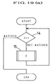
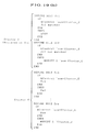
- Fig. 19(a) is a flowchart of a process including a loop and Fig. 19(b) shows rules corresponding thereto.
- Rule names Jr1 and Jr2 denote rules in the cluster J. These rules are similar to those in the case of fig. 18, and hence no further description will be given of them.
- a rule Ern is to be fired at the end of the execution of the cluster E.
- the value of the attribute ⁇ now of the cluster control working memory element is updated for the cluster J, and then the process returns to the decision step 14.
- the production system in principle is capable as well of performing procedural processes through utilization of cluster control, but since there is a limit to man's programming ability, only production systems composed of hundreds to thousands of rules at most have been the largest ever implemented regardless of the scale and capabilities of the computer used; namely, it is very difficult, with the prior art, to implement a large scale production system which calls for complicated sequence control.
- the invention also offers a program conversion method therefor.
- the production system of the present invention has a constitution in which control expression elements, each describing an instruction for specifying a cluster to be invoked next for execution or an instruction for other flow control, are arranged in the order of execution to consist a control expression part separate from the clusters for processing. And an instruction for a return to the said control expression part is described in the action part of an appropriate production rule in a cluster, in place of the cluster specifying instruction, so that sequential invocation of clusters, can be performed following the instructions described in the control expression part.
- each control expression element in the control expression part is converted to one or more production rules to thereby convert the control expression part to a control cluster composed of one or more production rules, and the description to the effect of returning to the control expression part from a cluster for processings, given in the action part of an appropriate rule of the cluster, is converted to appropriate actions, thereby producing a rule base production system in which the rules for the control expression part and the clusters of production rules for processing are combined with each other to ensure integrated operations.
- Fig. 1 shows the outline of a program for use in the present invention.
- Reference numerals 16, 17 and 18 indicate clusters each composed of a plurality of rules written for each subtask.
- the clusters are denoted by A, B,..., and N, respectively, and the rules belonging to each cluster are described in the conventional rule base.
- Reference numeral 19 indicates a control expression added in the present invention, for defining the order of execution of the clusters.
- the control expression makes unnecessary the control condition and the control action described for cluster control for sequential processing, branching, looping, etc. as mentioned previously in connection with the prior art in the condition and action parts of each rule in all the clusters.
- Fig. 2 exemplifies some control expression elements for describing the control expression in a form similar to the BASIC language, a conventional procedural language, or the like.
- the control expression elements are instructions for executing different processes. By predetermining tens of control expression elements it is possible to execute almost all types of procedural processes.
- any desired cluster control can be effected by describing the control expression with one or more of such control expression elements which are selected therefrom as required for the processes to be executed.
- Fig. 3(a) is a flowchart for executing the clusters A and B in this order and Fig. 3(b) a program prepared according to the present invention for executing the flow.
- the program comprises a control expression part 20, a cluster A21 and a cluster B22, which correspond to the control expression 19, the cluster 16 and the cluster 17 shown in Fig. 1.
- the control expression part 20 consists of a declare statement 23 "DEFINE MAIN" indicating the beginning of the control expression part, steps 24 through 26 describing a plurality of control expression elements in a sequential order, and a declaration "END" indicating the end of the control expression part.
- the steps 24 and 25 are instructions for invoking and executing clusters specified by name in the steps, and the control expression part 20 specifies the order of execution of a plurality of clusters.
- "FIRE" in this embodiment is one of the control expression elements exemplified in Fig. 2 and is a descriptor for selecting a required cluster by name and invoking it, i.e. an instruction for specifying, as candidates for firing, only rules belonging to the required cluster, and excluding all the rules belonging to other clusters.
- the cluster A consists of a declare statement 27 "DEFINE CLUSTER cluster A" indicating the beginning of the cluster A, rules Ar1' through Arn' and a declaration “END” indicating the end of the cluster.
- Each rule has a condition part 28 and an action part 29 as is the case with the conventional rule.
- a descriptor 30 added to the rule Arn' which is fired at the end to complete processings of the cluster A is a descriptor 30 "DONE(Aexp)".
- the descriptor "DONE(Aexp)" is one that, after completion of the processings of the cluster A, commands that control be transferred to a step next to the step 24 in the control expression part that selected the cluster A and, at the same time, commands that the value of information of a name "Aexp" obtained by the processing of the cluster A is stored in a preassigned memory.
- the cluster B also consists of a declare statement, rules Br1' through Brm' and a declaration "END" as is the case with the cluster A.
- the execution procedure therefor is similar to the relationship between a main routine and a subroutine in a procedural language. That is, the cluster A is driven based on the first step of the control expression part 20 and the value of information Aexp obtained by the execution of the cluster A is stored in a preassigned memory in accordance with the descriptor "DONE(Aexp)" described in the action part of the rule which is selected at the end of the execution of the cluster A, after which control returns to the second step in the control expression part 20.
- the cluster B is driven based on the second step and the value of information Bexp obtained by the execution of the cluster B is stored in a preassigned memory in accordance with a descriptor "DONE(Bexp)" described in the rule which is selected at the end of the execution of the cluster B, after which control returns to the third step in the control expression part as in the above.
- the third step is a description "STOP" and the process terminates accordingly. In this way, a plurality of clusters can be driven one after another following descriptions of flow control in conventional procedural form.
- the afore-mentioned traditional cluster control technique permits only transfer of control between clusters.
- This embodiment passes information obtained by processing of each cluster to the control expression part as well as transfers control between each cluster and the control expression part.
- the present invention achieves this through very simple programming, but the conventional cluster control technique will involve very complex programming therefor.
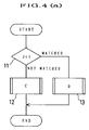
- Fig. 4(a) is a flowchart including a branch and Fig. 4(b) shows a program prepared therefor according to the present invention.
- the program consists of a control expression part 31, a cluster C32 and a cluster D33.
- the control expression part 31 includes a declare statement, a plurality of steps and a declaration "END" as is the case with the above-described embodiment, and the control expression part 31 is to perform branch processing as a whole.
- the "GOTO" in the third step is an instruction for unconditional jump to a step labeled @L2.
- Steps headed with a "@" such as @L1, the fourth, and @L2, the sixth step will hereinafter be referred to as label lines. They are not instructions for performing something in particular but are denotations which are referred to when jumping to a desired step in the control expression part 31. The use of such labels allows ease in jumping to required steps in those cases where the number of loops or branches executed is large.
- the clusters C32 and D33 each consist of a declare statement, rules and a declaration "END" as in the above example.
- This embodiment is to execute a flow including a branch. The operation therefor will herein below be described.
- the process In the first step it is determined whether or not the condition "Jc1" is met, and if it is met, then the process will jump to the fourth step labeled @L1. Since the fourth step is a mere label line, control is passed to the fifth step, in which the cluster D is invoked. Upon completion of the execution of the cluster D, control is transferred via the sixth step labeled @L2 to the seventh step "STOP", at which the process is terminated.
- control is passed to the second step, whereat the cluster C is invoked.
- control is transferred via the sixth step labeled @L2 to the seventh step "STOP", at which the process is terminated.
- conditional processing as mentioned above, the process can be branched to either one of the two clusters, and a conditional branch to three or more clusters can be processed in a similar way.
- Fig. 5(a) is a flowchart including a loop and Fig. 5(b) shows a program prepared therefor according to the present invention.
- the program consists of a control expression part 34 and a cluster E35 as in the above.
- the control expression part 34 includes a declare statement, descriptions of a plurality of steps and a declaration "END", and this control expression part is to perform looping as a whole.
- the "@START" in the first step is a label and the other steps are described in the same manner as in the above.
- This embodiment is to perform looping as follows: In the first step labeled @START nothing is done and control is passed to the second step, at which is determined whether or not a condition "Jc1" is met. If the condition is met, the process jumps to the fifth step labeled @L1 and then to the sixth step "STOP", in which the process is terminated.
- control is passed to the third step "FIRE cluster E” to invoke the cluster E.
- This is followed by an execution of the fourth step "GOTO @START", resulting in transfer of control to the second step, via the label @START on the first step at which it is determined again whether or not the above-mentioned condition is met.
- this embodiment it is determined whether a certain condition is met or not and the result of this test is used to branch the process to the step for invoking the cluster E or the step for terminating the process.
- This embodiment thus makes a looping process which is an important case of conditional branch possible.
- the production system according to the present invention operates on a program which consists of such a combination of the control expression part and the clusters as mentioned above.
- the most important point of programming is to describe the control sequence in the control expression part in the same fashion as in the case of using conventional procedural languages, group the rules into appropriate named clusters and describe merely "DONE (parameter)" in the action part of the rule in each cluster from which the process is to return to the control expression part.
- the present invention allows much more ease in describing the control expression part for cluster control than in the prior art.
- a large scale production system which could not have been realized due to the complexity involved in describing the control condition and the control action, can easily be implemented through use of the above programming method.
- the present invention permits control of the execution sequence of a plurality of clusters through very simple programming.
- a programmer describes in the control expression part a branch by GOTO and a loop by REPEAT/UNTIL in the same manner as in the case of the conventional procedural languages and passes control to a desired step to thereby make the description of the control action in the rule unnecessary. Accordingly, procedural cluster-wise flow control can be described very simply by a proper combination of these control expression elements.
- the programmer needs only to describe the control expression part and the rules separately of each other as mentioned above and need not consider the description of the control condition in each rule.
- the program as they stand consisting of a combination of the control expression part and the rules described as mentioned above cannot be used with conventional production systems for the following reasons: Since the conventional production systems lack the concept of control expression, its description is meaningless, and since the descriptions of the condition and action for the cluster control are removed from the rules because of the use of the control expression, it is impossible, with such a program, to effect cluster control in the prior art production systems. In the following, a description will be given of a method for converting the program to a form applicable to the production systems employing the conventional rule base in order to guarantee the compatibility.
- the basic concept of this method is to convert each step of the control expression part to one or more rules, insert a control condition and a control action into each rule in each cluster in the same manner as in the prior art, and convert the descriptor "DONE (parameter)" to the corresponding operations.
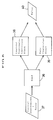
- Fig. 6 is a conceptual diagram illustrating in a block form the method and apparatus by which the program consisting of the control expression part and rules, prepared according to the present invention, is converted to a rule base which is an integration of the two and can be executed by conventional production systems.
- reference numeral 36 indicates a read station, which reads a program 37 described as a combination of the control expression part and rules and separates the program 37 into the control expression part and the rules by referring to the declare statement at the head of each part indicating whether it is the control expression part or a cluster and the declaration "END".
- the control expression part is a description consisting of a combined set of steps selected out of tens of control expression elements together with variables included therein.
- the steps are each converted to one or more rules of a conventional format applicable to the prior art production system. That is, a control expression conversion block 38 reads respective steps of the control expression part separated by the read station 36 and converts them to rules of the conventional format which are capable of the functions corresponding to instructions as depicted in the right-hand column of Fig. 2.
- the rules separated by the read station 36 are also converted by a rule conversion block 39 to rules described in the conventional format.
- the program 37 is converted to a group of rules 40 of the format executable in the conventional production system and the control expression part becomes a control cluster.
- Fig. 7 is a diagram illustrating an example of a method for converting the control expression part to rules of a format which can be enabled in the conventional production system. The method will be described as being applied to the conversion of the step "FIRE cluster A.”
- Reference numeral 41 indicates a step of the control expression part, headed by a logical line number representing the location where it is in the control expression part.
- the logical line number though not actually used, is an expedient means for conversion and every tenth number, for example, is used as the logical line number after the manner of the line number in BASIC.
- Reference numeral 42 denotes a template which is prepared corresponding to the said step of the control expression in which the processings to be executed in the step are described in the traditional rule format but variable parts (fields of ⁇ , ⁇ and ⁇ in this example) are held blank. Appropriate parts of a character string forming the step 41 are extracted out thereof and inlaid in the variable parts of the template 42 to form a rule 43.
- Templates corresponding to all types of the steps of thecontrol expression are stored in a memory associated with the controlexpression converting block 38 in Fig. 6, and the template describedhere above is an example.
- the logical line number "20" of the step and "cluster A" which is the name of the cluster to be invoked are extracted out of the control expression and inlaid in the fields " ⁇ " and “ ⁇ ” in the template 42, and further, the logical line number "30" of the control expression part to which the process is to return is inlaid in the field " ⁇ ", obtaining the rule 43 of the conventional format as shown.
- steps of the control expression part are converted to rules of the format acceptable to the conventional production system.
- reference numeral 44 indicates a step of the control expression part, headed by its logical line number "40", for example, 45 a template prepared for the said step, and 46 a rule of the conventional format into which the step is converted.
- the template 45 differs from the afore-mentioned one 42 in three points.
- the action part includes only a description "MODIFY 2 ⁇ NO ⁇ " in place of the description "MODIFY 1 ⁇ now ⁇ "
- one step of the control expression part is converted to two rules.
- the value of the attribute " ⁇ now" does not change because the step being executed does not involve a cluster control for invoking another cluster, and only the value of the attribute representing the logical line number undergoes a change because the process could jump from this step to another in the control expression part.
- the reason for conversion of this step to two rules is to describe actions in both cases where a condition "the value resulting from the processings in the preceding cluster is 35" is met and where the condition is not met.
- the line number of the step being executed the type of the value for use in the conditional processing, the value 35, the logical line number of the step to which the process jumps by the "GOTO”, and the logical line number of the next step in the control expression part are inlaid in the fields " ⁇ ", " ⁇ ", “ ⁇ ", “ ⁇ ” and " ⁇ "of the template, respectively.
- the label line @L1 is assumed of a logical line number 600.
- Fig. 9 shows how rules in the cluster group separated from the control expression part according to the present invention are each converted to rules of conventional format.
- This can easily be implemented through utilization of known text manipulation techniques. In this way, the rules 47 are converted to those 48 of the conventional format.
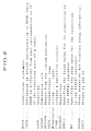
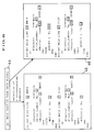
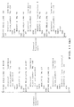
- a program consisting of the control expression part and rules according to the present invention can be converted to a rule base which can be enabled by the prior art production system as an integration of the control expression part and the rules. More specifically, the program for sequencing, shown in Fig. 3, the program for branching, shown in Fig. 4, and the program for looping, shown in fig. 5, are converted to rule bases depicted in Figs. 10, 11 and 12, respectively. It is self-evident that they are exactly identical in function with conventional rule base programs though somewhat different in form therefrom.
- the rules converted as described above are loaded on a production memory 1 of a conventional production system shown in Fig. 15 to work as a production system.
- clusters each consisting of rules of the above mentioned configuration can easily be enabled in a desired order by use of control expressions described in the same manner as in the case of a procedural language.
- control expression elements other than those mentioned above can similarly be converted to rules of the conventional format. Now, a description will be given specifically of the conversion of statements GOSUB/RETURN and REPEAT /UNTIL.
- the "GOSUB” is an instruction for calling a subroutine and the "RETURN” an instruction for a return to the line next to the line from which the subroutine was called.
- What is essentially required for calling a subroutine in a subroutine, i.e. for nesting subroutine calls, is to monitor on a stack on the memory the number of subroutine calls made counting from the first call in the main routine and the location of the line of the calling subroutine to which control is to be returned.
- two classes of working memory elements are used which serve as a stack pointer and as a stack, respectively.
- the working memory element for use as the stack pointer is to indicate the number of subroutine calls made in succession counting from the first call in the main routine and only one working memory element of the said class is used all the time.
- Its class name and attribute name are, for example, " ⁇ Depth” and " ⁇ sp”, respectively.
- the stack is formed by working memory elements for storing the logical line number of the calling routine to which control is to be returned by the statement "RETURN", and they have a class name "Call-stack” and attribute names " ⁇ Ret" and " ⁇ depth”. These working memory elements are generated one by one for each subroutine call and are deleted one by one for each return to the calling routine by "RETURN".
- Fig. 13(a) shows a template for converting "GOSUB” to a rule.
- "& depth ⁇ sp IS ⁇ ” is a step in which the number of subroutine calls made in succession starting in the main routine, i.e. the depth of the stack, is copied to a variable ⁇ irrespective of its value
- "MAKE” is an instruction for generating a frame of the above-mentioned stack, i.e. a working memory element having a class name "Call stack” and attribute names " ⁇ Ret" and " ⁇ depth”.
- ⁇ is a logical line number indicating the line in the calling routine to which control is to be returned
- ⁇ is a copy of the current value of the stack pointer " ⁇ sp”.
- MODIFY 2 ⁇ No ⁇ is an action for jumping to the label of a subroutine corresponding to the logical line number " ⁇ ”.
- MODIFY 3 ⁇ sp ⁇ means that the value of the stack pointer " ⁇ sp” indicating the depth of the stack is incremented by one for each subroutine call.
- Fig. 13(b) shows a template for converting "RETURN” to a rule.
- MODIFY 2 ⁇ NO ⁇ is an action for jumping to the line number " ⁇ " of the original routine to which control is to be returned.
- MODIFY 3 ⁇ sp ⁇ means that the stored value of the depth of the subroutine call is decremented by one for each return from the called subroutine to the calling routine.
- REMOVE is an instruction for removing the working memory element forming the stack frame.
- the nesting of "GOSUB/RETURN" can be achieved by using working memory elements indicating the depth of the current subroutine call and the ligical line number of the line in the calling routine to which control is to be returned and by changing the values of the working memory elements, generating other working memory elements and removing them as referred to above.
- nested “REPEAT/UNTIL” can also be converted to rules by using working memory elements indicating the depth or level of the current looping and the line in the parent loop to which control is to be returned and by changing the values of the working memory elements, generating or removing such working memory elements.
- control expression part is described using a procedural language, it may also be a table describing the execution sequence.
- the descriptor "DONE (parameter)" for returning from a cluster to the control expression part was assumed to be used in the rule which is fired at the end of the execution in a cluster, it may also be used in a plurality of rules. That is, where it is desired to return control to the control expression part after firing of either one of the first and second rules depending upon the state of processing in the cluster, the descriptor "DONE (parameter)” is used in the both rules. Of course, the descriptor may also be used in three or more rules as required, and after firing of any one of the rules with the description "DONE (parameter)" the processings in the cluster is completed and then control returns to the control expression part.
- the information obtained by the processings in the cluster is stored, as required, by the descriptor "DONE (parameter)" of the rule, in the data passing working memory element having the class name "Result” and two attribute names " ⁇ type” and “ ⁇ DONE” as described previously.
- DONE parameter
- the template in this case is one such as shown in Fig. 14 in which an action "MODIFY Result ⁇ type ⁇ ⁇ DONE ⁇ " is inserted, ⁇ and ⁇ being the type and the value of the information passed, respectively.
- control working memory elements can be dispensed with by using, like the afore-mentioned data transfer working memory element, a working memory element with the class name Control" and the two attribute names " ⁇ now" and " ⁇ NO".
- the present invention permits easy flow control as in the case of using a procedural language and facilitates the construction of a large scale production system.
Landscapes
- Engineering & Computer Science (AREA)
- Theoretical Computer Science (AREA)
- Computing Systems (AREA)
- Data Mining & Analysis (AREA)
- Evolutionary Computation (AREA)
- Physics & Mathematics (AREA)
- Computational Linguistics (AREA)
- General Engineering & Computer Science (AREA)
- General Physics & Mathematics (AREA)
- Mathematical Physics (AREA)
- Software Systems (AREA)
- Artificial Intelligence (AREA)
- Devices For Executing Special Programs (AREA)
- Stored Programmes (AREA)
Applications Claiming Priority (2)
| Application Number | Priority Date | Filing Date | Title |
|---|---|---|---|
| JP2130695A JP3049561B2 (ja) | 1990-05-21 | 1990-05-21 | プロダクションシステムとプロダクションシステムの変換装置 |
| JP130695/90 | 1990-05-21 |
Publications (2)
| Publication Number | Publication Date |
|---|---|
| EP0483359A1 true EP0483359A1 (de) | 1992-05-06 |
| EP0483359A4 EP0483359A4 (en) | 1992-11-19 |
Family
ID=15040414
Family Applications (1)
| Application Number | Title | Priority Date | Filing Date |
|---|---|---|---|
| EP19910905903 Withdrawn EP0483359A4 (en) | 1990-05-21 | 1991-03-20 | Production system |
Country Status (4)
| Country | Link |
|---|---|
| US (2) | US5452453A (de) |
| EP (1) | EP0483359A4 (de) |
| JP (1) | JP3049561B2 (de) |
| WO (1) | WO1991018343A1 (de) |
Cited By (1)
| Publication number | Priority date | Publication date | Assignee | Title |
|---|---|---|---|---|
| EP0571779A1 (de) * | 1992-05-26 | 1993-12-01 | AMMON, Kurt | Adaptive Computersystem |
Families Citing this family (17)
| Publication number | Priority date | Publication date | Assignee | Title |
|---|---|---|---|---|
| KR100243806B1 (ko) * | 1996-06-07 | 2000-02-01 | 가네꼬 히사시 | 공정 플로 작성 시스템 |
| US5893105A (en) * | 1996-11-12 | 1999-04-06 | Micrografx, Inc. | Executable flowchart |
| US6154765A (en) * | 1998-03-18 | 2000-11-28 | Pasocs Llc | Distributed digital rule processor for single system image on a clustered network and method |
| US6226627B1 (en) * | 1998-04-17 | 2001-05-01 | Fuji Xerox Co., Ltd. | Method and system for constructing adaptive and resilient software |
| US6701516B1 (en) * | 1998-05-21 | 2004-03-02 | Qifang Li | P++ software |
| US6934696B1 (en) | 2000-09-15 | 2005-08-23 | Bently Nevada, Llc | Custom rule system and method for expert systems |
| US7065745B2 (en) * | 2002-12-16 | 2006-06-20 | Sun Microsystems, Inc. | System and method for evaluating and executing hierarchies of rules |
| US7203826B2 (en) * | 2005-02-18 | 2007-04-10 | Qualcomm Incorporated | Method and apparatus for managing a return stack |
| US8578347B1 (en) * | 2006-12-28 | 2013-11-05 | The Mathworks, Inc. | Determining stack usage of generated code from a model |
| US7853546B2 (en) * | 2007-03-09 | 2010-12-14 | General Electric Company | Enhanced rule execution in expert systems |
| US8418135B2 (en) * | 2007-05-31 | 2013-04-09 | Red Hat, Inc. | Method and apparatus to abstract away rule languages |
| JP2008305004A (ja) * | 2007-06-05 | 2008-12-18 | Ricoh Co Ltd | 画像形成装置、アプリケーション実行方法及びアプリケーション実行プログラム |
| US8495560B2 (en) * | 2009-10-12 | 2013-07-23 | International Business Machines Corporation | Converting an activity diagram into code |
| US9361165B2 (en) * | 2009-12-03 | 2016-06-07 | International Business Machines Corporation | Automated merger of logically associated messages in a message queue |
| IN2013MU03243A (de) * | 2013-10-15 | 2015-07-17 | Tata Consultancy Services Ltd | |
| JP6602511B2 (ja) * | 2017-06-02 | 2019-11-06 | 三菱電機株式会社 | プログラムコード生成装置およびプログラムコード生成プログラム |
| US11232096B2 (en) | 2018-09-06 | 2022-01-25 | Optumsoft, Inc. | Automatic generation of an efficient rule set implementation |
Family Cites Families (16)
| Publication number | Priority date | Publication date | Assignee | Title |
|---|---|---|---|---|
| US3651281A (en) * | 1969-06-06 | 1972-03-21 | Carl H Becker | Laser recording system using photomagnetically magnetizable storage medium |
| US4568370A (en) * | 1982-09-29 | 1986-02-04 | Corning Glass Works | Optical fiber preform and method |
| US4658370A (en) * | 1984-06-07 | 1987-04-14 | Teknowledge, Inc. | Knowledge engineering tool |
| US4809219A (en) * | 1985-06-26 | 1989-02-28 | International Business Machines Corporation | Method for processing an expert system rulebase on a system having limited memory |
| JPH0652502B2 (ja) * | 1987-05-06 | 1994-07-06 | 株式会社日立製作所 | 推論方法 |
| US4837735A (en) * | 1987-06-09 | 1989-06-06 | Martin Marietta Energy Systems, Inc. | Parallel machine architecture for production rule systems |
| JP2506991B2 (ja) * | 1987-09-25 | 1996-06-12 | 松下電器産業株式会社 | 回路変換システムと回路変換方法と反転論理生成方法および論理設計システム |
| US5204941A (en) * | 1987-09-30 | 1993-04-20 | Sharp Kabushiki Kaisha | Element checking system for use in forward inference system |
| US5006992A (en) * | 1987-09-30 | 1991-04-09 | Du Pont De Nemours And Company | Process control system with reconfigurable expert rules and control modules |
| US5165011A (en) * | 1988-09-22 | 1992-11-17 | Omron Tateisi Electronics Co. | System for switching a rule group |
| US5101362A (en) * | 1988-12-14 | 1992-03-31 | Digital Equipment Corporation | Modular blackboard based expert system |
| JPH07107668B2 (ja) * | 1989-01-25 | 1995-11-15 | 株式会社日立製作所 | 知識処理ツールの推論方法 |
| JP2507593B2 (ja) * | 1989-04-25 | 1996-06-12 | 株式会社東芝 | 推論方式 |
| US5241652A (en) * | 1989-06-08 | 1993-08-31 | Digital Equipment Corporation | System for performing rule partitioning in a rete network |
| JPH047743A (ja) * | 1990-04-26 | 1992-01-13 | Toshiba Corp | 推論システム |
| US5303332A (en) * | 1990-07-30 | 1994-04-12 | Digital Equipment Corporation | Language for economically building complex, large-scale, efficient, rule-based systems and sub-systems |
-
1990
- 1990-05-21 JP JP2130695A patent/JP3049561B2/ja not_active Expired - Fee Related
-
1991
- 1991-03-20 WO PCT/JP1991/000374 patent/WO1991018343A1/ja not_active Ceased
- 1991-03-20 EP EP19910905903 patent/EP0483359A4/en not_active Withdrawn
-
1994
- 1994-10-21 US US08/327,230 patent/US5452453A/en not_active Expired - Fee Related
-
1995
- 1995-06-07 US US08/486,936 patent/US5615308A/en not_active Expired - Fee Related
Cited By (2)
| Publication number | Priority date | Publication date | Assignee | Title |
|---|---|---|---|---|
| EP0571779A1 (de) * | 1992-05-26 | 1993-12-01 | AMMON, Kurt | Adaptive Computersystem |
| US6678667B1 (en) | 1992-05-26 | 2004-01-13 | Kurt Ammon | Adaptive computer system |
Also Published As
| Publication number | Publication date |
|---|---|
| JPH0424826A (ja) | 1992-01-28 |
| US5452453A (en) | 1995-09-19 |
| EP0483359A4 (en) | 1992-11-19 |
| WO1991018343A1 (fr) | 1991-11-28 |
| US5615308A (en) | 1997-03-25 |
| JP3049561B2 (ja) | 2000-06-05 |
Similar Documents
| Publication | Publication Date | Title |
|---|---|---|
| US5615308A (en) | Rule-based production system adapted for complex procedures flow | |
| US4712189A (en) | Table driven translator | |
| JP4448881B2 (ja) | コンピュータプログラムを発生する方法及びシステム | |
| JP2577763B2 (ja) | 図形認識システム及びその動作方法 | |
| US5005119A (en) | User interactive control of computer programs and corresponding versions of input/output data flow | |
| CA1316262C (en) | Version management tool | |
| US5699310A (en) | Method and apparatus for a fully inherited object-oriented computer system for generating source code from user-entered specifications | |
| US5990906A (en) | Undo feature for a graphical programming system | |
| US4853873A (en) | Knowledge information processing system and method thereof | |
| US4730315A (en) | Diagrammatic method of testing program | |
| EP0612014B1 (de) | Menuabfragesystem | |
| US4943968A (en) | Method of displaying execution trace in a logic programming language processing system | |
| US5781905A (en) | Program generating method combining data item part with database manipulation part | |
| US6014514A (en) | System for generating and graphically displaying call stack information for processing elements in a parallel processing system | |
| EP0638862B1 (de) | Sprachverarbeitungssystem und -verfahren | |
| JPH0916382A (ja) | プログラム開発支援システム | |
| US5724559A (en) | Method for displaying ISPF panels in a VM non-ISPF environment | |
| Mittelbach et al. | The docstrip program | |
| JP5458065B2 (ja) | モジュールの構造解析を支援する装置及びプログラム | |
| CN113568607B (zh) | 一种数字程序实现方法和系统 | |
| JP2500632B2 (ja) | プログラムパタ―ンカストマイズ方式 | |
| JPH07334358A (ja) | 手順編集装置 | |
| JPH01144124A (ja) | コンピュータ装置 | |
| JPH01162922A (ja) | 表示ウィンドウ管理方式 | |
| CN114968417A (zh) | 一种函数调用方法、装置及设备 |
Legal Events
| Date | Code | Title | Description |
|---|---|---|---|
| PUAI | Public reference made under article 153(3) epc to a published international application that has entered the european phase |
Free format text: ORIGINAL CODE: 0009012 |
|
| 17P | Request for examination filed |
Effective date: 19920213 |
|
| AK | Designated contracting states |
Kind code of ref document: A1 Designated state(s): DE FR GB |
|
| A4 | Supplementary search report drawn up and despatched |
Effective date: 19920928 |
|
| AK | Designated contracting states |
Kind code of ref document: A4 Designated state(s): DE FR GB |
|
| STAA | Information on the status of an ep patent application or granted ep patent |
Free format text: STATUS: THE APPLICATION HAS BEEN WITHDRAWN |
|
| 18W | Application withdrawn |
Withdrawal date: 19960606 |