EP0483378A1 - Cliche typographique en resine photodurcie - Google Patents
Cliche typographique en resine photodurcie Download PDFInfo
- Publication number
- EP0483378A1 EP0483378A1 EP91909145A EP91909145A EP0483378A1 EP 0483378 A1 EP0483378 A1 EP 0483378A1 EP 91909145 A EP91909145 A EP 91909145A EP 91909145 A EP91909145 A EP 91909145A EP 0483378 A1 EP0483378 A1 EP 0483378A1
- Authority
- EP
- European Patent Office
- Prior art keywords
- layer
- relief
- photosensitive resin
- thickness
- light exposure
- Prior art date
- Legal status (The legal status is an assumption and is not a legal conclusion. Google has not performed a legal analysis and makes no representation as to the accuracy of the status listed.)
- Granted
Links
- 229920005989 resin Polymers 0.000 title claims abstract description 164
- 239000011347 resin Substances 0.000 title claims abstract description 164
- 239000000758 substrate Substances 0.000 claims description 45
- 239000007788 liquid Substances 0.000 claims description 40
- 238000000034 method Methods 0.000 claims description 19
- 238000004519 manufacturing process Methods 0.000 claims description 11
- QSHDDOUJBYECFT-UHFFFAOYSA-N mercury Chemical compound [Hg] QSHDDOUJBYECFT-UHFFFAOYSA-N 0.000 claims description 7
- 229910052753 mercury Inorganic materials 0.000 claims description 7
- 229910001507 metal halide Inorganic materials 0.000 claims description 5
- 150000005309 metal halides Chemical class 0.000 claims description 5
- 238000000016 photochemical curing Methods 0.000 claims description 5
- 238000007639 printing Methods 0.000 abstract description 72
- 230000008719 thickening Effects 0.000 abstract 1
- 239000010410 layer Substances 0.000 description 220
- -1 i.e. Substances 0.000 description 17
- 239000000203 mixture Substances 0.000 description 17
- 239000010408 film Substances 0.000 description 16
- NIXOWILDQLNWCW-UHFFFAOYSA-M Acrylate Chemical compound [O-]C(=O)C=C NIXOWILDQLNWCW-UHFFFAOYSA-M 0.000 description 14
- 239000007787 solid Substances 0.000 description 14
- 239000003112 inhibitor Substances 0.000 description 12
- 239000000178 monomer Substances 0.000 description 12
- 239000003999 initiator Substances 0.000 description 11
- LYCAIKOWRPUZTN-UHFFFAOYSA-N Ethylene glycol Chemical compound OCCO LYCAIKOWRPUZTN-UHFFFAOYSA-N 0.000 description 10
- 239000012790 adhesive layer Substances 0.000 description 9
- 230000000052 comparative effect Effects 0.000 description 9
- 230000000694 effects Effects 0.000 description 9
- 229920002635 polyurethane Polymers 0.000 description 9
- 239000004814 polyurethane Substances 0.000 description 9
- 238000012719 thermal polymerization Methods 0.000 description 9
- 239000011521 glass Substances 0.000 description 8
- MTHSVFCYNBDYFN-UHFFFAOYSA-N diethylene glycol Chemical compound OCCOCCO MTHSVFCYNBDYFN-UHFFFAOYSA-N 0.000 description 6
- FQPSGWSUVKBHSU-UHFFFAOYSA-N methacrylamide Chemical compound CC(=C)C(N)=O FQPSGWSUVKBHSU-UHFFFAOYSA-N 0.000 description 6
- 229920005862 polyol Polymers 0.000 description 6
- DNIAPMSPPWPWGF-UHFFFAOYSA-N Propylene glycol Chemical compound CC(O)CO DNIAPMSPPWPWGF-UHFFFAOYSA-N 0.000 description 5
- 230000015572 biosynthetic process Effects 0.000 description 5
- 229920000728 polyester Polymers 0.000 description 5
- 229920001730 Moisture cure polyurethane Polymers 0.000 description 4
- 238000006243 chemical reaction Methods 0.000 description 4
- 238000005259 measurement Methods 0.000 description 4
- 229920001228 polyisocyanate Polymers 0.000 description 4
- 239000005056 polyisocyanate Substances 0.000 description 4
- 229920001451 polypropylene glycol Polymers 0.000 description 4
- 150000007519 polyprotic acids Polymers 0.000 description 4
- 238000003860 storage Methods 0.000 description 4
- XLYOFNOQVPJJNP-UHFFFAOYSA-N water Substances O XLYOFNOQVPJJNP-UHFFFAOYSA-N 0.000 description 4
- CSCPPACGZOOCGX-UHFFFAOYSA-N Acetone Chemical compound CC(C)=O CSCPPACGZOOCGX-UHFFFAOYSA-N 0.000 description 3
- UHOVQNZJYSORNB-UHFFFAOYSA-N Benzene Chemical compound C1=CC=CC=C1 UHOVQNZJYSORNB-UHFFFAOYSA-N 0.000 description 3
- MUBZPKHOEPUJKR-UHFFFAOYSA-N Oxalic acid Chemical compound OC(=O)C(O)=O MUBZPKHOEPUJKR-UHFFFAOYSA-N 0.000 description 3
- 206010034972 Photosensitivity reaction Diseases 0.000 description 3
- 239000002202 Polyethylene glycol Substances 0.000 description 3
- 239000004743 Polypropylene Substances 0.000 description 3
- OFOBLEOULBTSOW-UHFFFAOYSA-N Propanedioic acid Natural products OC(=O)CC(O)=O OFOBLEOULBTSOW-UHFFFAOYSA-N 0.000 description 3
- HEMHJVSKTPXQMS-UHFFFAOYSA-M Sodium hydroxide Chemical compound [OH-].[Na+] HEMHJVSKTPXQMS-UHFFFAOYSA-M 0.000 description 3
- YXFVVABEGXRONW-UHFFFAOYSA-N Toluene Chemical compound CC1=CC=CC=C1 YXFVVABEGXRONW-UHFFFAOYSA-N 0.000 description 3
- 238000001723 curing Methods 0.000 description 3
- 229920001971 elastomer Polymers 0.000 description 3
- 125000002887 hydroxy group Chemical group [H]O* 0.000 description 3
- IQPQWNKOIGAROB-UHFFFAOYSA-N isocyanate group Chemical group [N-]=C=O IQPQWNKOIGAROB-UHFFFAOYSA-N 0.000 description 3
- 230000007246 mechanism Effects 0.000 description 3
- 230000036211 photosensitivity Effects 0.000 description 3
- 229920006267 polyester film Polymers 0.000 description 3
- 229920001223 polyethylene glycol Polymers 0.000 description 3
- 229920000642 polymer Polymers 0.000 description 3
- 150000003077 polyols Chemical class 0.000 description 3
- 229920001155 polypropylene Polymers 0.000 description 3
- 238000002360 preparation method Methods 0.000 description 3
- 239000005060 rubber Substances 0.000 description 3
- 239000000243 solution Substances 0.000 description 3
- 239000000126 substance Substances 0.000 description 3
- 239000004094 surface-active agent Substances 0.000 description 3
- 229920006305 unsaturated polyester Polymers 0.000 description 3
- MYRTYDVEIRVNKP-UHFFFAOYSA-N 1,2-Divinylbenzene Chemical compound C=CC1=CC=CC=C1C=C MYRTYDVEIRVNKP-UHFFFAOYSA-N 0.000 description 2
- KWVGIHKZDCUPEU-UHFFFAOYSA-N 2,2-dimethoxy-2-phenylacetophenone Chemical compound C=1C=CC=CC=1C(OC)(OC)C(=O)C1=CC=CC=C1 KWVGIHKZDCUPEU-UHFFFAOYSA-N 0.000 description 2
- JKNCOURZONDCGV-UHFFFAOYSA-N 2-(dimethylamino)ethyl 2-methylprop-2-enoate Chemical compound CN(C)CCOC(=O)C(C)=C JKNCOURZONDCGV-UHFFFAOYSA-N 0.000 description 2
- RKOOOVKGLHCLTP-UHFFFAOYSA-N 2-methylprop-2-enoic acid;propane-1,2,3-triol Chemical compound CC(=C)C(O)=O.OCC(O)CO RKOOOVKGLHCLTP-UHFFFAOYSA-N 0.000 description 2
- JOYRKODLDBILNP-UHFFFAOYSA-N Ethyl urethane Chemical compound CCOC(N)=O JOYRKODLDBILNP-UHFFFAOYSA-N 0.000 description 2
- VZCYOOQTPOCHFL-OWOJBTEDSA-N Fumaric acid Chemical compound OC(=O)\C=C\C(O)=O VZCYOOQTPOCHFL-OWOJBTEDSA-N 0.000 description 2
- PEDCQBHIVMGVHV-UHFFFAOYSA-N Glycerine Chemical compound OCC(O)CO PEDCQBHIVMGVHV-UHFFFAOYSA-N 0.000 description 2
- QIGBRXMKCJKVMJ-UHFFFAOYSA-N Hydroquinone Chemical compound OC1=CC=C(O)C=C1 QIGBRXMKCJKVMJ-UHFFFAOYSA-N 0.000 description 2
- WOBHKFSMXKNTIM-UHFFFAOYSA-N Hydroxyethyl methacrylate Chemical compound CC(=C)C(=O)OCCO WOBHKFSMXKNTIM-UHFFFAOYSA-N 0.000 description 2
- 238000004566 IR spectroscopy Methods 0.000 description 2
- XEEYBQQBJWHFJM-UHFFFAOYSA-N Iron Chemical compound [Fe] XEEYBQQBJWHFJM-UHFFFAOYSA-N 0.000 description 2
- 239000004698 Polyethylene Substances 0.000 description 2
- CDBYLPFSWZWCQE-UHFFFAOYSA-L Sodium Carbonate Chemical compound [Na+].[Na+].[O-]C([O-])=O CDBYLPFSWZWCQE-UHFFFAOYSA-L 0.000 description 2
- PPBRXRYQALVLMV-UHFFFAOYSA-N Styrene Chemical compound C=CC1=CC=CC=C1 PPBRXRYQALVLMV-UHFFFAOYSA-N 0.000 description 2
- KKEYFWRCBNTPAC-UHFFFAOYSA-N Terephthalic acid Chemical compound OC(=O)C1=CC=C(C(O)=O)C=C1 KKEYFWRCBNTPAC-UHFFFAOYSA-N 0.000 description 2
- 239000002253 acid Substances 0.000 description 2
- 239000000853 adhesive Substances 0.000 description 2
- 230000001070 adhesive effect Effects 0.000 description 2
- WNLRTRBMVRJNCN-UHFFFAOYSA-N adipic acid Chemical compound OC(=O)CCCCC(O)=O WNLRTRBMVRJNCN-UHFFFAOYSA-N 0.000 description 2
- 239000012670 alkaline solution Substances 0.000 description 2
- XXROGKLTLUQVRX-UHFFFAOYSA-N allyl alcohol Chemical compound OCC=C XXROGKLTLUQVRX-UHFFFAOYSA-N 0.000 description 2
- ISAOCJYIOMOJEB-UHFFFAOYSA-N benzoin Chemical compound C=1C=CC=CC=1C(O)C(=O)C1=CC=CC=C1 ISAOCJYIOMOJEB-UHFFFAOYSA-N 0.000 description 2
- 229910021538 borax Inorganic materials 0.000 description 2
- WERYXYBDKMZEQL-UHFFFAOYSA-N butane-1,4-diol Chemical compound OCCCCO WERYXYBDKMZEQL-UHFFFAOYSA-N 0.000 description 2
- YCIMNLLNPGFGHC-UHFFFAOYSA-N catechol Chemical compound OC1=CC=CC=C1O YCIMNLLNPGFGHC-UHFFFAOYSA-N 0.000 description 2
- 230000008859 change Effects 0.000 description 2
- 239000003795 chemical substances by application Substances 0.000 description 2
- 150000001875 compounds Chemical class 0.000 description 2
- 238000012790 confirmation Methods 0.000 description 2
- 230000003247 decreasing effect Effects 0.000 description 2
- SZXQTJUDPRGNJN-UHFFFAOYSA-N dipropylene glycol Chemical compound OCCCOCCCO SZXQTJUDPRGNJN-UHFFFAOYSA-N 0.000 description 2
- 238000004090 dissolution Methods 0.000 description 2
- 238000001035 drying Methods 0.000 description 2
- 206010016256 fatigue Diseases 0.000 description 2
- WGCNASOHLSPBMP-UHFFFAOYSA-N hydroxyacetaldehyde Natural products OCC=O WGCNASOHLSPBMP-UHFFFAOYSA-N 0.000 description 2
- 230000006698 induction Effects 0.000 description 2
- 230000001678 irradiating effect Effects 0.000 description 2
- QQVIHTHCMHWDBS-UHFFFAOYSA-N isophthalic acid Chemical compound OC(=O)C1=CC=CC(C(O)=O)=C1 QQVIHTHCMHWDBS-UHFFFAOYSA-N 0.000 description 2
- 238000003475 lamination Methods 0.000 description 2
- 125000002496 methyl group Chemical group [H]C([H])([H])* 0.000 description 2
- TXXHDPDFNKHHGW-UHFFFAOYSA-N muconic acid Chemical compound OC(=O)C=CC=CC(O)=O TXXHDPDFNKHHGW-UHFFFAOYSA-N 0.000 description 2
- BDJRBEYXGGNYIS-UHFFFAOYSA-N nonanedioic acid Chemical compound OC(=O)CCCCCCCC(O)=O BDJRBEYXGGNYIS-UHFFFAOYSA-N 0.000 description 2
- XNGIFLGASWRNHJ-UHFFFAOYSA-N phthalic acid Chemical compound OC(=O)C1=CC=CC=C1C(O)=O XNGIFLGASWRNHJ-UHFFFAOYSA-N 0.000 description 2
- WLJVNTCWHIRURA-UHFFFAOYSA-N pimelic acid Chemical compound OC(=O)CCCCCC(O)=O WLJVNTCWHIRURA-UHFFFAOYSA-N 0.000 description 2
- 239000002985 plastic film Substances 0.000 description 2
- 229920000573 polyethylene Polymers 0.000 description 2
- CYIDZMCFTVVTJO-UHFFFAOYSA-N pyromellitic acid Chemical compound OC(=O)C1=CC(C(O)=O)=C(C(O)=O)C=C1C(O)=O CYIDZMCFTVVTJO-UHFFFAOYSA-N 0.000 description 2
- 239000011342 resin composition Substances 0.000 description 2
- 229920006395 saturated elastomer Polymers 0.000 description 2
- CXMXRPHRNRROMY-UHFFFAOYSA-N sebacic acid Chemical compound OC(=O)CCCCCCCCC(O)=O CXMXRPHRNRROMY-UHFFFAOYSA-N 0.000 description 2
- 238000007493 shaping process Methods 0.000 description 2
- 235000010339 sodium tetraborate Nutrition 0.000 description 2
- 125000006850 spacer group Chemical group 0.000 description 2
- 238000005507 spraying Methods 0.000 description 2
- TYFQFVWCELRYAO-UHFFFAOYSA-N suberic acid Chemical compound OC(=O)CCCCCCC(O)=O TYFQFVWCELRYAO-UHFFFAOYSA-N 0.000 description 2
- DVKJHBMWWAPEIU-UHFFFAOYSA-N toluene 2,4-diisocyanate Chemical compound CC1=CC=C(N=C=O)C=C1N=C=O DVKJHBMWWAPEIU-UHFFFAOYSA-N 0.000 description 2
- VZCYOOQTPOCHFL-UHFFFAOYSA-N trans-butenedioic acid Natural products OC(=O)C=CC(O)=O VZCYOOQTPOCHFL-UHFFFAOYSA-N 0.000 description 2
- BSVBQGMMJUBVOD-UHFFFAOYSA-N trisodium borate Chemical compound [Na+].[Na+].[Na+].[O-]B([O-])[O-] BSVBQGMMJUBVOD-UHFFFAOYSA-N 0.000 description 2
- 229940124543 ultraviolet light absorber Drugs 0.000 description 2
- 238000005406 washing Methods 0.000 description 2
- DNIAPMSPPWPWGF-VKHMYHEASA-N (+)-propylene glycol Chemical compound C[C@H](O)CO DNIAPMSPPWPWGF-VKHMYHEASA-N 0.000 description 1
- PUPZLCDOIYMWBV-UHFFFAOYSA-N (+/-)-1,3-Butanediol Chemical compound CC(O)CCO PUPZLCDOIYMWBV-UHFFFAOYSA-N 0.000 description 1
- XVOUMQNXTGKGMA-OWOJBTEDSA-N (E)-glutaconic acid Chemical compound OC(=O)C\C=C\C(O)=O XVOUMQNXTGKGMA-OWOJBTEDSA-N 0.000 description 1
- 239000001124 (E)-prop-1-ene-1,2,3-tricarboxylic acid Substances 0.000 description 1
- MSAHTMIQULFMRG-UHFFFAOYSA-N 1,2-diphenyl-2-propan-2-yloxyethanone Chemical compound C=1C=CC=CC=1C(OC(C)C)C(=O)C1=CC=CC=C1 MSAHTMIQULFMRG-UHFFFAOYSA-N 0.000 description 1
- QWQFVUQPHUKAMY-UHFFFAOYSA-N 1,2-diphenyl-2-propoxyethanone Chemical compound C=1C=CC=CC=1C(OCCC)C(=O)C1=CC=CC=C1 QWQFVUQPHUKAMY-UHFFFAOYSA-N 0.000 description 1
- YPFDHNVEDLHUCE-UHFFFAOYSA-N 1,3-propanediol Substances OCCCO YPFDHNVEDLHUCE-UHFFFAOYSA-N 0.000 description 1
- AZQWKYJCGOJGHM-UHFFFAOYSA-N 1,4-benzoquinone Chemical compound O=C1C=CC(=O)C=C1 AZQWKYJCGOJGHM-UHFFFAOYSA-N 0.000 description 1
- CBCKQZAAMUWICA-UHFFFAOYSA-N 1,4-phenylenediamine Chemical compound NC1=CC=C(N)C=C1 CBCKQZAAMUWICA-UHFFFAOYSA-N 0.000 description 1
- DKEGCUDAFWNSSO-UHFFFAOYSA-N 1,8-dibromooctane Chemical compound BrCCCCCCCCBr DKEGCUDAFWNSSO-UHFFFAOYSA-N 0.000 description 1
- ILBBNQMSDGAAPF-UHFFFAOYSA-N 1-(6-hydroxy-6-methylcyclohexa-2,4-dien-1-yl)propan-1-one Chemical compound CCC(=O)C1C=CC=CC1(C)O ILBBNQMSDGAAPF-UHFFFAOYSA-N 0.000 description 1
- RTBFRGCFXZNCOE-UHFFFAOYSA-N 1-methylsulfonylpiperidin-4-one Chemical compound CS(=O)(=O)N1CCC(=O)CC1 RTBFRGCFXZNCOE-UHFFFAOYSA-N 0.000 description 1
- WJFKNYWRSNBZNX-UHFFFAOYSA-N 10H-phenothiazine Chemical compound C1=CC=C2NC3=CC=CC=C3SC2=C1 WJFKNYWRSNBZNX-UHFFFAOYSA-N 0.000 description 1
- BJELTSYBAHKXRW-UHFFFAOYSA-N 2,4,6-triallyloxy-1,3,5-triazine Chemical compound C=CCOC1=NC(OCC=C)=NC(OCC=C)=N1 BJELTSYBAHKXRW-UHFFFAOYSA-N 0.000 description 1
- SMZOUWXMTYCWNB-UHFFFAOYSA-N 2-(2-methoxy-5-methylphenyl)ethanamine Chemical compound COC1=CC=C(C)C=C1CCN SMZOUWXMTYCWNB-UHFFFAOYSA-N 0.000 description 1
- JAHNSTQSQJOJLO-UHFFFAOYSA-N 2-(3-fluorophenyl)-1h-imidazole Chemical compound FC1=CC=CC(C=2NC=CN=2)=C1 JAHNSTQSQJOJLO-UHFFFAOYSA-N 0.000 description 1
- FALRKNHUBBKYCC-UHFFFAOYSA-N 2-(chloromethyl)pyridine-3-carbonitrile Chemical compound ClCC1=NC=CC=C1C#N FALRKNHUBBKYCC-UHFFFAOYSA-N 0.000 description 1
- NIXOWILDQLNWCW-UHFFFAOYSA-N 2-Propenoic acid Natural products OC(=O)C=C NIXOWILDQLNWCW-UHFFFAOYSA-N 0.000 description 1
- CCJAYIGMMRQRAO-UHFFFAOYSA-N 2-[4-[(2-hydroxyphenyl)methylideneamino]butyliminomethyl]phenol Chemical compound OC1=CC=CC=C1C=NCCCCN=CC1=CC=CC=C1O CCJAYIGMMRQRAO-UHFFFAOYSA-N 0.000 description 1
- DBBSWURSQHDBEQ-UHFFFAOYSA-N 2-butan-2-yloxy-1,2-diphenylethanone Chemical compound C=1C=CC=CC=1C(OC(C)CC)C(=O)C1=CC=CC=C1 DBBSWURSQHDBEQ-UHFFFAOYSA-N 0.000 description 1
- DZZAHLOABNWIFA-UHFFFAOYSA-N 2-butoxy-1,2-diphenylethanone Chemical compound C=1C=CC=CC=1C(OCCCC)C(=O)C1=CC=CC=C1 DZZAHLOABNWIFA-UHFFFAOYSA-N 0.000 description 1
- KMNCBSZOIQAUFX-UHFFFAOYSA-N 2-ethoxy-1,2-diphenylethanone Chemical compound C=1C=CC=CC=1C(OCC)C(=O)C1=CC=CC=C1 KMNCBSZOIQAUFX-UHFFFAOYSA-N 0.000 description 1
- CKKQLOUBFINSIB-UHFFFAOYSA-N 2-hydroxy-1,2,2-triphenylethanone Chemical compound C=1C=CC=CC=1C(C=1C=CC=CC=1)(O)C(=O)C1=CC=CC=C1 CKKQLOUBFINSIB-UHFFFAOYSA-N 0.000 description 1
- FSJIAFAPQGPONH-UHFFFAOYSA-N 2-hydroxy-1,2-diphenylbutan-1-one Chemical compound C=1C=CC=CC=1C(O)(CC)C(=O)C1=CC=CC=C1 FSJIAFAPQGPONH-UHFFFAOYSA-N 0.000 description 1
- RZCDMINQJLGWEP-UHFFFAOYSA-N 2-hydroxy-1,2-diphenylpent-4-en-1-one Chemical compound C=1C=CC=CC=1C(CC=C)(O)C(=O)C1=CC=CC=C1 RZCDMINQJLGWEP-UHFFFAOYSA-N 0.000 description 1
- DIVXVZXROTWKIH-UHFFFAOYSA-N 2-hydroxy-1,2-diphenylpropan-1-one Chemical compound C=1C=CC=CC=1C(O)(C)C(=O)C1=CC=CC=C1 DIVXVZXROTWKIH-UHFFFAOYSA-N 0.000 description 1
- 125000000954 2-hydroxyethyl group Chemical group [H]C([*])([H])C([H])([H])O[H] 0.000 description 1
- OMIGHNLMNHATMP-UHFFFAOYSA-N 2-hydroxyethyl prop-2-enoate Chemical compound OCCOC(=O)C=C OMIGHNLMNHATMP-UHFFFAOYSA-N 0.000 description 1
- VHSHLMUCYSAUQU-UHFFFAOYSA-N 2-hydroxypropyl methacrylate Chemical compound CC(O)COC(=O)C(C)=C VHSHLMUCYSAUQU-UHFFFAOYSA-N 0.000 description 1
- BQZJOQXSCSZQPS-UHFFFAOYSA-N 2-methoxy-1,2-diphenylethanone Chemical compound C=1C=CC=CC=1C(OC)C(=O)C1=CC=CC=C1 BQZJOQXSCSZQPS-UHFFFAOYSA-N 0.000 description 1
- IMAHLMWOKFATMM-UHFFFAOYSA-N 2-methoxy-1,2-diphenylpropan-1-one Chemical compound C=1C=CC=CC=1C(C)(OC)C(=O)C1=CC=CC=C1 IMAHLMWOKFATMM-UHFFFAOYSA-N 0.000 description 1
- XLLXMBCBJGATSP-UHFFFAOYSA-N 2-phenylethenol Chemical compound OC=CC1=CC=CC=C1 XLLXMBCBJGATSP-UHFFFAOYSA-N 0.000 description 1
- 125000003903 2-propenyl group Chemical group [H]C([*])([H])C([H])=C([H])[H] 0.000 description 1
- HRPVXLWXLXDGHG-UHFFFAOYSA-N Acrylamide Chemical compound NC(=O)C=C HRPVXLWXLXDGHG-UHFFFAOYSA-N 0.000 description 1
- NLZUEZXRPGMBCV-UHFFFAOYSA-N Butylhydroxytoluene Chemical compound CC1=CC(C(C)(C)C)=C(O)C(C(C)(C)C)=C1 NLZUEZXRPGMBCV-UHFFFAOYSA-N 0.000 description 1
- OKTJSMMVPCPJKN-UHFFFAOYSA-N Carbon Chemical compound [C] OKTJSMMVPCPJKN-UHFFFAOYSA-N 0.000 description 1
- 229920002160 Celluloid Polymers 0.000 description 1
- RYGMFSIKBFXOCR-UHFFFAOYSA-N Copper Chemical compound [Cu] RYGMFSIKBFXOCR-UHFFFAOYSA-N 0.000 description 1
- 239000004641 Diallyl-phthalate Substances 0.000 description 1
- 239000004386 Erythritol Substances 0.000 description 1
- UNXHWFMMPAWVPI-UHFFFAOYSA-N Erythritol Natural products OCC(O)C(O)CO UNXHWFMMPAWVPI-UHFFFAOYSA-N 0.000 description 1
- LFQSCWFLJHTTHZ-UHFFFAOYSA-N Ethanol Chemical compound CCO LFQSCWFLJHTTHZ-UHFFFAOYSA-N 0.000 description 1
- 244000043261 Hevea brasiliensis Species 0.000 description 1
- 239000005057 Hexamethylene diisocyanate Substances 0.000 description 1
- CERQOIWHTDAKMF-UHFFFAOYSA-N Methacrylic acid Chemical compound CC(=C)C(O)=O CERQOIWHTDAKMF-UHFFFAOYSA-N 0.000 description 1
- TXXHDPDFNKHHGW-CCAGOZQPSA-N Muconic acid Natural products OC(=O)\C=C/C=C\C(O)=O TXXHDPDFNKHHGW-CCAGOZQPSA-N 0.000 description 1
- CNCOEDDPFOAUMB-UHFFFAOYSA-N N-Methylolacrylamide Chemical compound OCNC(=O)C=C CNCOEDDPFOAUMB-UHFFFAOYSA-N 0.000 description 1
- 239000004952 Polyamide Substances 0.000 description 1
- 239000004793 Polystyrene Substances 0.000 description 1
- 239000004115 Sodium Silicate Substances 0.000 description 1
- 244000028419 Styrax benzoin Species 0.000 description 1
- 235000000126 Styrax benzoin Nutrition 0.000 description 1
- KDYFGRWQOYBRFD-UHFFFAOYSA-N Succinic acid Natural products OC(=O)CCC(O)=O KDYFGRWQOYBRFD-UHFFFAOYSA-N 0.000 description 1
- 235000008411 Sumatra benzointree Nutrition 0.000 description 1
- BGNXCDMCOKJUMV-UHFFFAOYSA-N Tert-Butylhydroquinone Chemical compound CC(C)(C)C1=CC(O)=CC=C1O BGNXCDMCOKJUMV-UHFFFAOYSA-N 0.000 description 1
- ZJCCRDAZUWHFQH-UHFFFAOYSA-N Trimethylolpropane Chemical compound CCC(CO)(CO)CO ZJCCRDAZUWHFQH-UHFFFAOYSA-N 0.000 description 1
- DAKWPKUUDNSNPN-UHFFFAOYSA-N Trimethylolpropane triacrylate Chemical compound C=CC(=O)OCC(CC)(COC(=O)C=C)COC(=O)C=C DAKWPKUUDNSNPN-UHFFFAOYSA-N 0.000 description 1
- OKKRPWIIYQTPQF-UHFFFAOYSA-N Trimethylolpropane trimethacrylate Chemical compound CC(=C)C(=O)OCC(CC)(COC(=O)C(C)=C)COC(=O)C(C)=C OKKRPWIIYQTPQF-UHFFFAOYSA-N 0.000 description 1
- XTXRWKRVRITETP-UHFFFAOYSA-N Vinyl acetate Chemical compound CC(=O)OC=C XTXRWKRVRITETP-UHFFFAOYSA-N 0.000 description 1
- BZHJMEDXRYGGRV-UHFFFAOYSA-N Vinyl chloride Chemical group ClC=C BZHJMEDXRYGGRV-UHFFFAOYSA-N 0.000 description 1
- HCHKCACWOHOZIP-UHFFFAOYSA-N Zinc Chemical compound [Zn] HCHKCACWOHOZIP-UHFFFAOYSA-N 0.000 description 1
- KNSXNCFKSZZHEA-UHFFFAOYSA-N [3-prop-2-enoyloxy-2,2-bis(prop-2-enoyloxymethyl)propyl] prop-2-enoate Chemical compound C=CC(=O)OCC(COC(=O)C=C)(COC(=O)C=C)COC(=O)C=C KNSXNCFKSZZHEA-UHFFFAOYSA-N 0.000 description 1
- UKLDJPRMSDWDSL-UHFFFAOYSA-L [dibutyl(dodecanoyloxy)stannyl] dodecanoate Chemical compound CCCCCCCCCCCC(=O)O[Sn](CCCC)(CCCC)OC(=O)CCCCCCCCCCC UKLDJPRMSDWDSL-UHFFFAOYSA-L 0.000 description 1
- 238000005299 abrasion Methods 0.000 description 1
- 150000008065 acid anhydrides Chemical class 0.000 description 1
- 229940091181 aconitic acid Drugs 0.000 description 1
- 150000001252 acrylic acid derivatives Chemical class 0.000 description 1
- WNLRTRBMVRJNCN-UHFFFAOYSA-L adipate(2-) Chemical compound [O-]C(=O)CCCCC([O-])=O WNLRTRBMVRJNCN-UHFFFAOYSA-L 0.000 description 1
- 239000001361 adipic acid Substances 0.000 description 1
- 235000011037 adipic acid Nutrition 0.000 description 1
- 150000001298 alcohols Chemical class 0.000 description 1
- 229910052782 aluminium Inorganic materials 0.000 description 1
- XAGFODPZIPBFFR-UHFFFAOYSA-N aluminium Chemical compound [Al] XAGFODPZIPBFFR-UHFFFAOYSA-N 0.000 description 1
- JFCQEDHGNNZCLN-UHFFFAOYSA-N anhydrous glutaric acid Natural products OC(=O)CCCC(O)=O JFCQEDHGNNZCLN-UHFFFAOYSA-N 0.000 description 1
- 239000007864 aqueous solution Substances 0.000 description 1
- 239000003125 aqueous solvent Substances 0.000 description 1
- 229960002130 benzoin Drugs 0.000 description 1
- 230000001588 bifunctional effect Effects 0.000 description 1
- QUDWYFHPNIMBFC-UHFFFAOYSA-N bis(prop-2-enyl) benzene-1,2-dicarboxylate Chemical compound C=CCOC(=O)C1=CC=CC=C1C(=O)OCC=C QUDWYFHPNIMBFC-UHFFFAOYSA-N 0.000 description 1
- KDYFGRWQOYBRFD-NUQCWPJISA-N butanedioic acid Chemical compound O[14C](=O)CC[14C](O)=O KDYFGRWQOYBRFD-NUQCWPJISA-N 0.000 description 1
- 235000010354 butylated hydroxytoluene Nutrition 0.000 description 1
- 229910052799 carbon Inorganic materials 0.000 description 1
- 238000005266 casting Methods 0.000 description 1
- 229920002301 cellulose acetate Polymers 0.000 description 1
- HRYZWHHZPQKTII-UHFFFAOYSA-N chloroethane Chemical compound CCCl HRYZWHHZPQKTII-UHFFFAOYSA-N 0.000 description 1
- GTZCVFVGUGFEME-IWQZZHSRSA-N cis-aconitic acid Chemical compound OC(=O)C\C(C(O)=O)=C\C(O)=O GTZCVFVGUGFEME-IWQZZHSRSA-N 0.000 description 1
- HNEGQIOMVPPMNR-IHWYPQMZSA-N citraconic acid Chemical compound OC(=O)C(/C)=C\C(O)=O HNEGQIOMVPPMNR-IHWYPQMZSA-N 0.000 description 1
- 229940018557 citraconic acid Drugs 0.000 description 1
- 238000007796 conventional method Methods 0.000 description 1
- 229910052802 copper Inorganic materials 0.000 description 1
- 239000010949 copper Substances 0.000 description 1
- 239000013039 cover film Substances 0.000 description 1
- 125000000113 cyclohexyl group Chemical group [H]C1([H])C([H])([H])C([H])([H])C([H])(*)C([H])([H])C1([H])[H] 0.000 description 1
- 230000007812 deficiency Effects 0.000 description 1
- 238000011161 development Methods 0.000 description 1
- 125000004386 diacrylate group Chemical group 0.000 description 1
- 239000012975 dibutyltin dilaurate Substances 0.000 description 1
- JXCHMDATRWUOAP-UHFFFAOYSA-N diisocyanatomethylbenzene Chemical compound O=C=NC(N=C=O)C1=CC=CC=C1 JXCHMDATRWUOAP-UHFFFAOYSA-N 0.000 description 1
- UNXHWFMMPAWVPI-ZXZARUISSA-N erythritol Chemical compound OC[C@H](O)[C@H](O)CO UNXHWFMMPAWVPI-ZXZARUISSA-N 0.000 description 1
- 235000019414 erythritol Nutrition 0.000 description 1
- 229940009714 erythritol Drugs 0.000 description 1
- 150000002148 esters Chemical class 0.000 description 1
- 229960003750 ethyl chloride Drugs 0.000 description 1
- 125000004494 ethyl ester group Chemical group 0.000 description 1
- 125000001495 ethyl group Chemical group [H]C([H])([H])C([H])([H])* 0.000 description 1
- 230000001747 exhibiting effect Effects 0.000 description 1
- 238000009472 formulation Methods 0.000 description 1
- 239000001530 fumaric acid Substances 0.000 description 1
- 235000011187 glycerol Nutrition 0.000 description 1
- 125000003055 glycidyl group Chemical group C(C1CO1)* 0.000 description 1
- 235000019382 gum benzoic Nutrition 0.000 description 1
- 150000004820 halides Chemical class 0.000 description 1
- RRAMGCGOFNQTLD-UHFFFAOYSA-N hexamethylene diisocyanate Chemical compound O=C=NCCCCCCN=C=O RRAMGCGOFNQTLD-UHFFFAOYSA-N 0.000 description 1
- FBPFZTCFMRRESA-UHFFFAOYSA-N hexane-1,2,3,4,5,6-hexol Chemical compound OCC(O)C(O)C(O)C(O)CO FBPFZTCFMRRESA-UHFFFAOYSA-N 0.000 description 1
- 230000006872 improvement Effects 0.000 description 1
- 230000002401 inhibitory effect Effects 0.000 description 1
- 230000000977 initiatory effect Effects 0.000 description 1
- 229910052742 iron Inorganic materials 0.000 description 1
- 239000012948 isocyanate Substances 0.000 description 1
- 150000002513 isocyanates Chemical class 0.000 description 1
- 125000001449 isopropyl group Chemical group [H]C([H])([H])C([H])(*)C([H])([H])[H] 0.000 description 1
- 238000010030 laminating Methods 0.000 description 1
- 230000000670 limiting effect Effects 0.000 description 1
- VZCYOOQTPOCHFL-UPHRSURJSA-N maleic acid Chemical compound OC(=O)\C=C/C(O)=O VZCYOOQTPOCHFL-UPHRSURJSA-N 0.000 description 1
- 239000011976 maleic acid Substances 0.000 description 1
- 239000000463 material Substances 0.000 description 1
- HNEGQIOMVPPMNR-NSCUHMNNSA-N mesaconic acid Chemical compound OC(=O)C(/C)=C/C(O)=O HNEGQIOMVPPMNR-NSCUHMNNSA-N 0.000 description 1
- 229910052751 metal Inorganic materials 0.000 description 1
- 239000002184 metal Substances 0.000 description 1
- LVHBHZANLOWSRM-UHFFFAOYSA-N methylenebutanedioic acid Natural products OC(=O)CC(=C)C(O)=O LVHBHZANLOWSRM-UHFFFAOYSA-N 0.000 description 1
- HNEGQIOMVPPMNR-UHFFFAOYSA-N methylfumaric acid Natural products OC(=O)C(C)=CC(O)=O HNEGQIOMVPPMNR-UHFFFAOYSA-N 0.000 description 1
- 230000005012 migration Effects 0.000 description 1
- 238000013508 migration Methods 0.000 description 1
- JESXATFQYMPTNL-UHFFFAOYSA-N mono-hydroxyphenyl-ethylene Natural products OC1=CC=CC=C1C=C JESXATFQYMPTNL-UHFFFAOYSA-N 0.000 description 1
- 238000000465 moulding Methods 0.000 description 1
- ZIUHHBKFKCYYJD-UHFFFAOYSA-N n,n'-methylenebisacrylamide Chemical compound C=CC(=O)NCNC(=O)C=C ZIUHHBKFKCYYJD-UHFFFAOYSA-N 0.000 description 1
- OMNKZBIFPJNNIO-UHFFFAOYSA-N n-(2-methyl-4-oxopentan-2-yl)prop-2-enamide Chemical compound CC(=O)CC(C)(C)NC(=O)C=C OMNKZBIFPJNNIO-UHFFFAOYSA-N 0.000 description 1
- YQCFXPARMSSRRK-UHFFFAOYSA-N n-[6-(prop-2-enoylamino)hexyl]prop-2-enamide Chemical compound C=CC(=O)NCCCCCCNC(=O)C=C YQCFXPARMSSRRK-UHFFFAOYSA-N 0.000 description 1
- 125000001280 n-hexyl group Chemical group C(CCCCC)* 0.000 description 1
- QMQNMBYPQFQQPK-UHFFFAOYSA-N n-methoxyprop-2-enamide Chemical compound CONC(=O)C=C QMQNMBYPQFQQPK-UHFFFAOYSA-N 0.000 description 1
- 125000004123 n-propyl group Chemical group [H]C([H])([H])C([H])([H])C([H])([H])* 0.000 description 1
- 229920003052 natural elastomer Polymers 0.000 description 1
- 229920001194 natural rubber Polymers 0.000 description 1
- 238000005457 optimization Methods 0.000 description 1
- 235000006408 oxalic acid Nutrition 0.000 description 1
- NWVVVBRKAWDGAB-UHFFFAOYSA-N p-methoxyphenol Chemical compound COC1=CC=C(O)C=C1 NWVVVBRKAWDGAB-UHFFFAOYSA-N 0.000 description 1
- 230000036961 partial effect Effects 0.000 description 1
- WXZMFSXDPGVJKK-UHFFFAOYSA-N pentaerythritol Chemical compound OCC(CO)(CO)CO WXZMFSXDPGVJKK-UHFFFAOYSA-N 0.000 description 1
- 229950000688 phenothiazine Drugs 0.000 description 1
- OXNIZHLAWKMVMX-UHFFFAOYSA-N picric acid Chemical compound OC1=C([N+]([O-])=O)C=C([N+]([O-])=O)C=C1[N+]([O-])=O OXNIZHLAWKMVMX-UHFFFAOYSA-N 0.000 description 1
- 239000000049 pigment Substances 0.000 description 1
- 229920003229 poly(methyl methacrylate) Polymers 0.000 description 1
- 229920002647 polyamide Polymers 0.000 description 1
- 229920001748 polybutylene Polymers 0.000 description 1
- 229920000515 polycarbonate Polymers 0.000 description 1
- 239000004417 polycarbonate Substances 0.000 description 1
- 238000006068 polycondensation reaction Methods 0.000 description 1
- 229920005906 polyester polyol Polymers 0.000 description 1
- 239000004926 polymethyl methacrylate Substances 0.000 description 1
- 229920002223 polystyrene Polymers 0.000 description 1
- 229920000166 polytrimethylene carbonate Polymers 0.000 description 1
- 229920000915 polyvinyl chloride Polymers 0.000 description 1
- 239000004800 polyvinyl chloride Substances 0.000 description 1
- 230000002265 prevention Effects 0.000 description 1
- HJWLCRVIBGQPNF-UHFFFAOYSA-N prop-2-enylbenzene Chemical compound C=CCC1=CC=CC=C1 HJWLCRVIBGQPNF-UHFFFAOYSA-N 0.000 description 1
- 230000002829 reductive effect Effects 0.000 description 1
- 230000001105 regulatory effect Effects 0.000 description 1
- 238000004904 shortening Methods 0.000 description 1
- 229910000029 sodium carbonate Inorganic materials 0.000 description 1
- 239000001488 sodium phosphate Substances 0.000 description 1
- 229910000162 sodium phosphate Inorganic materials 0.000 description 1
- NTHWMYGWWRZVTN-UHFFFAOYSA-N sodium silicate Chemical compound [Na+].[Na+].[O-][Si]([O-])=O NTHWMYGWWRZVTN-UHFFFAOYSA-N 0.000 description 1
- 229910052911 sodium silicate Inorganic materials 0.000 description 1
- 235000019832 sodium triphosphate Nutrition 0.000 description 1
- 239000002904 solvent Substances 0.000 description 1
- 238000003892 spreading Methods 0.000 description 1
- 230000007480 spreading Effects 0.000 description 1
- 229910001220 stainless steel Inorganic materials 0.000 description 1
- 239000010935 stainless steel Substances 0.000 description 1
- 229940014800 succinic anhydride Drugs 0.000 description 1
- 229920003051 synthetic elastomer Polymers 0.000 description 1
- 239000005061 synthetic rubber Substances 0.000 description 1
- 239000004250 tert-Butylhydroquinone Substances 0.000 description 1
- 235000019281 tert-butylhydroquinone Nutrition 0.000 description 1
- 238000012360 testing method Methods 0.000 description 1
- GTZCVFVGUGFEME-UHFFFAOYSA-N trans-aconitic acid Natural products OC(=O)CC(C(O)=O)=CC(O)=O GTZCVFVGUGFEME-UHFFFAOYSA-N 0.000 description 1
- RYFMWSXOAZQYPI-UHFFFAOYSA-K trisodium phosphate Chemical compound [Na+].[Na+].[Na+].[O-]P([O-])([O-])=O RYFMWSXOAZQYPI-UHFFFAOYSA-K 0.000 description 1
- 239000006097 ultraviolet radiation absorber Substances 0.000 description 1
- 229910052724 xenon Inorganic materials 0.000 description 1
- FHNFHKCVQCLJFQ-UHFFFAOYSA-N xenon atom Chemical compound [Xe] FHNFHKCVQCLJFQ-UHFFFAOYSA-N 0.000 description 1
- 125000006839 xylylene group Chemical group 0.000 description 1
- 229910052725 zinc Inorganic materials 0.000 description 1
- 239000011701 zinc Substances 0.000 description 1
Images
Classifications
-
- G—PHYSICS
- G03—PHOTOGRAPHY; CINEMATOGRAPHY; ANALOGOUS TECHNIQUES USING WAVES OTHER THAN OPTICAL WAVES; ELECTROGRAPHY; HOLOGRAPHY
- G03F—PHOTOMECHANICAL PRODUCTION OF TEXTURED OR PATTERNED SURFACES, e.g. FOR PRINTING, FOR PROCESSING OF SEMICONDUCTOR DEVICES; MATERIALS THEREFOR; ORIGINALS THEREFOR; APPARATUS SPECIALLY ADAPTED THEREFOR
- G03F7/00—Photomechanical, e.g. photolithographic, production of textured or patterned surfaces, e.g. printing surfaces; Materials therefor, e.g. comprising photoresists; Apparatus specially adapted therefor
- G03F7/004—Photosensitive materials
- G03F7/09—Photosensitive materials characterised by structural details, e.g. supports, auxiliary layers
- G03F7/095—Photosensitive materials characterised by structural details, e.g. supports, auxiliary layers having more than one photosensitive layer
- G03F7/0955—Photosensitive materials characterised by structural details, e.g. supports, auxiliary layers having more than one photosensitive layer one of the photosensitive systems comprising a non-macromolecular photopolymerisable compound having carbon-to-carbon double bonds, e.g. ethylenic compounds
Definitions
- the present invention relates to a photocured resin relief plate. More particularly, the present invention is concerned with a photocured resin relief plate having a high image reproducibility to thereby exhibit excellent printing performance, which plate is produced using a negative-type photosensitive resin in which a portion exposed to light becomes insoluble to a solvent.
- a relief printing plate of a resin is produced by providing a negative-type photosensitive resin layer, then irradiating it with light through a negative film to photocure selected portions of the photosensitive resin layer while leaving the other portions uncured and subsequently removing the uncured portions with an aqueous solvent or high air pressure.
- the resultant photocured resin relief plate is light in weight and ensures easy handling as compared to the lead relief plate, so that its use is rapidly being disseminated in the field of printing, particularly in the printing of newspapers.
- the performance of the photocured resin relief plate is greatly affected by the hardness of an employed photocured resin layer.
- a hard photocured resin relief plate it has a drawback in that dimness occurs in printed images having a large area, such as large letter images, solid images and halftone images, because of poor ink transferability, although it is excellent in reproducibility of fine lines and small dot images in printing, because the degree of deformation of a relief top portion by a printing pressure is small.
- a high printing pressure is employed in printing, in order to avoid the problem of the poor ink transferability mentioned above, another problem arises, such as the broadening of fine lines and small dot images in printing and lowering of printing resistance due to the abrasion of a relief top portion.
- a photocured resin relief plate which is comprised of two different photocured resin layers having a hardness difference of from 10 to 20° in Shore hardness.
- the hardness of the relief top layer was rendered greater than the hardness of the relief lower layer so that the deformation of the top portion of the relief by a printing pressure was minimized.
- the thickness of the relief layer at a highlight portion was identical with the thickness of the relief layer at a portion other than the highlight portion, so that the image broadening, especially at a highlight portion having a dot percent of 7 % or less by a printing pressure, was not satisfactorily suppressed to thereby cause production of a desired printed matter to be infeasible.
- a photocured resin relief plate which is comprised of two different resin layers having a modulus difference of at least 50 psi after light exposure to light, which resin layers resulted from a photosensitive resin layer corresponding to a relief lower layer and a photosensitive resin layer corresponding to a relief top layer, the former photosensitive resin layer exhibiting a photopolymerization rate of 1.5 to 200 times that of the latter photosensitive resin layer. Still further, in Japanese Patent Application Laid-Open Specification No.
- a photosensitive resin plate for relief printing which is comprised of two photosensitive resin layers, i.e., a photosensitive resin layer corresponding to a relief lower layer and a photosensitive resin layer corresponding to a relief top layer, the minimum insolubilization light exposure value of the former layer being 5 mJ/cm2 or less and up to 1/2 of that of the latter layer.
- the image size at the relief surface of the resultant printing plate can be rendered smaller than that of the negative film employed in the imagewise light exposure and printing performance can only be improved so much.
- the relief thickness at a highlight portion is identical with that at a portion other than the highlight portion, so that the broadening of printed images by a printing pressure cannot be prevented and satisfactory printed matter cannot be obtained.
- the present inventors have made extensive and intensive studies with a view toward developing a photocured resin relief plate having excellent image reproducibility and ensuring excellent printing performance.
- the present inventors have unexpectedly found that the thickness of the relief layer at a highlight portion having a dot percent of 7 % or less can be rendered smaller than the thickness of the relief layer at a portion other than the highlight portion by exposing two different photosensitive resin layers having different photosensitive characteristics, which photosensitive characteristics satisfy a specific relationship, to light for a predetermined period of time to thereby form a relief base layer and a relief top layer, and that thereby, the broadening of printed images can be suppressed at the highlight portion. Based on this novel finding, the present invention has been completed.
- a photocured resin relief plate comprising a substrate having a relief layer disposed thereon, the relief layer comprising base layer A and top layer B in this order from the substrate, the relief layer being formed by photocuring a multilayer photosensitive resin layer comprised of at least two different photosensitive resin layers having different photosensitive characteristics by imagewise light exposure, wherein the relief layer has at a highlight portion a thickness which is smaller than that at a portion other than the highlight portion, the highlight portion constituting a pattern having a dot percent of 7 % or less.
- a method for producing a photocured resin relief plate which comprises providing a photosensitive element comprising a substrate having disposed thereon a multilayer photosensitive resin layer comprising at least two different photosensitive resin layers having different photosensitive characteristics, wherein the multilayer photosensitive resin layer is comprised of a lower layer of a liquid photosensitive resin layer having minimum insolubilization light exposure value Q A and an upper layer of a liquid photosensitive resin layer having minimum insolubilization light exposure value Q B , the lower layer and the upper layer being arranged in this order from the substrate; imagewise exposing the photosensitive element on the multilayer photosensitive resin layer side to light to thereby form a photocured portion and an uncured portion; and subsequently washing-out the uncured portion with a developer to thereby form a relief layer comprising base layer A and top layer B respectively obtained from the lower layer and the upper layer, the relief layer having a highlight portion constituting a pattern having a dot percent of 7 % or less and a non-highlight portion
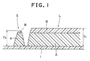
- Fig. 1 is a schematic cross-sectional view of the photocured resin relief plate of the present invention, wherein 1 designates a substrate, S designates a relief layer at a highlight portion which is comprised of base layer A and top layer B, and L designates a relief layer at portions (shadow portion and middle tone portion) other than the highlight portion, which relief layer is comprised of base layer A and top layer B.
- the total thickness of the photocured resin relief plate of the present invention i.e., the maximum value (thickness T1 of relief L in Fig. 1) of the total thickness of base layer A and top layer B, is appropriately selected within the range of not larger than 8 mm according to the type of a printing machine and printing conditions. The lower limit of the total thickness is about 0.3 mm.
- the maximum value of the thickness (thickness of layer B of relief L in Fig. 1) of top layer B constituting the printing face of the relief layer be not larger than 1/2 of the maximum value (identical with the total thickness of layer A and layer B of relief L in Fig. 1) of the total thickness of base layer A and top layer B, and not larger than 1 mm.
- the maximum value of the thickness of top layer B is preferably in the range of from 0.03 mm to 0.5 mm.
- the above-mentioned upper and lower layers have a total thickness of not larger than 8 mm and the thickness of the upper layer be not larger than 1/2 of the total thickness of the upper and lower layers and not larger than 1 mm, preferably in the range of from 0.03 to 0.5 mm.
- the relief thickness indicated by T2 in Fig.
- the thickness of the upper layer exceeds this range, the relief thickness at a highlight portion having a dot percent of 7 % or less of the obtained printing plate disadvantageously becomes too small as compared to the relief thickness at a portion other than the highlight portion, so that disadvantageously, the printing of an image carried at the highlight portion becomes difficult in a printing operation and, in somes cases, the formation of a relief at the highlight portion becomes difficult.
- the relief thickness (T2) at a highlight portion having a dot percent of 7 % or less of the obtained printing plate is smaller than the relief thickness (T1) at a portion other than the highlight portion by 20 to 100 ⁇ , more preferably 20 to 80 ⁇ .
- the relief thickness is the smallest at a least dot-percent highlight in a highlight portion constituting a pattern having a dot percent of 7 % or less, and gradually increases toward a dot percent of 7 %. In a region having a dot percent exceeding 7 %, the relief thickness is identical to the relief thickness at a portion other than the highlight portion.
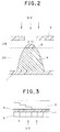
- the minimum insolubilization light exposure value Q B (millijoules/cm2) (hereinafter referred to as "mJ/cm2") of a photosensitive resin layer (2B in Fig. 2) for forming a top portion of a relief layer be not smaller than 23 mJ/cm2 as measured by the TO method (thickness optimization method) as described below, and that it be not smaller than 5 times the minimum insolubilization light exposure value Q A (mJ/cm2) of the photosensitive resin layer (2A in Fig. 2) for forming a base portion of the relief layer.
- the characteristic structure of the printing plate of the present invention i.e., a structure such that the relief thickness at a highlight portion constituting an image pattern having a dot percent of 7 % or less is smaller than the relief thickness at a portion other than the highlight portion, cannot be realized.
- layer 2B is partially cured at a portion which is in contact with layer 2A (a portion of layer 2B facing the negative film undergoes partial, slight curing as shown in Fig. 2, but layer 2B is not cured throughout the entire thickness thereof).
- a state shown in Fig. 2 is reached.
- the imagewise light exposure is terminated and then a development treatment is conducted, thereby obtaining a relief comprised of cured layer 2A and, having disposed thereon, a cured lower portion of layer 2B, i.e., a relief (relief S in Fig. 1) comprised of base layer A and a small top layer.
- the thickness of relief S is smaller than the thickness of a relief (relief L in Fig. 1) formed by completely curing layer 2B.
- the photocuring of the upper photosensitive resin layer require light exposure value Q B to be as large as 23 mJ/cm2 or more and that the photocuring of the lower photosensitive resin layer require light exposure value Q A to be as small as 1/5 Q B or less.
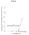
- a photopolymerization-type photosensitive resin layer having a length of 3 cm, a width of 15 cm and a thickness of 4 mm is provided on substrate 1 transparent to light and having adhesive layer 4.
- light shielding plates 5 each having a width of 3 cm are arranged so as to leave no gap therebetween on the exposed surface of the substrate, thereby covering the exposed surface.
- the resultant assembly is placed on a light exposure stand provided with a light source having an intensity set such that the intensity of light after traversing the substrate having the adhesive layer be 0.40 mW/cm2.
- light UV
- the other light shielding plates are subsequently successively removed at intervals of 30 seconds, and the application of light is terminated 30 seconds after removing the last (the rightmost one in Fig. 3) of the five plates.
- a photocured resin layer is obtained in which the section corresponding to the light shielding plate first removed has been exposed to light for 150 seconds and the section corresponding to the light shielding plate last removed has been exposed to light for 30 seconds, the intermediate sections present therebetween having been exposed to light for periods of time which are successively different by 30 seconds.
- a photosensitive resin is washed-out under predetermined dissolving conditions, followed by drying and post light exposure. Then, the thickness of the photocured resin layer formed on the substrate is measured in 1/100 millimeters.
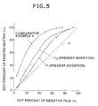
- the thus obtained relationship between the light exposure time and the thickness of the photocured resin plate is shown in a graph with one logarithmic axis, as in Fig. 4.
- An induction time (I.T., seconds) is determined from the light exposure time corresponding to a photocured resin thickness of 0 mm, and from this value, a minimum insolubilization light exposure value (mJ/cm2) can be calculated.
- I.T. seconds
- mJ/cm2 minimum insolubilization light exposure value
- the relief layer defined in the present invention is not limited to a relief layer having a relief formed directly on a substrate (e.g., a relief layer of the structure shown in Fig. 1), but includes other relief layer, such as a relief layer formed on a photocured resin layer (background layer) provided on a substrate.
- the photocured resin plate of the present invention which has been described hereinabove is comprised of two layers, i.e., base layer A and top layer B.
- the photocured resin plate of the present invention may further comprise an additional layer provided under base layer A, which additional layer is formed from a photosensitive resin layer having a minimum insolubilization light exposure value which is equal to or smaller than that of the photosensitive resin layer for forming base layer A.
- the relief layer be formed from two different photosensitive resins having different characteristics, which are in a liquid form.
- two different photosensitive resin layers, which are in a solid form are provided on a substrate, not only does the required molding temperature become higher than that required in the case of liquid photosensitive resin layers, but migration of components, such as a photopolymerization initiator and a thermal polymerization inhibitor also occurs between the two different solid photosensitive resin layers during the storage between the time of shaping and the time of imagewise light exposure, thereby causing the photosensitive characteristics of the layers to suffer from unfavorable changes. Therefore, it is requisite that the photosensitive resin for use in the present invention be liquid.
- liquid photosensitive resin there is no particular limitation with respect to the liquid photosensitive resin to be used in the present invention.
- liquid photosensitive resins include a liquid photosensitive resin comprising a prepolymer, such as an unsaturated polyester and an unsaturated polyurethane, a photopolymerization initiator and a thermal polymerization inhibitor.
- the above-mentioned unsaturated polyester can be obtained by a polycondensation reaction between an alcohol component comprising at least one polyol and an acid component comprising at least one unsaturated polybasic acid or derivative thereof (e.g., an acid anhydride, a methyl or an ethyl ester or an acid halide) and, optionally, a saturated polybasic acid added according to necessity.
- an alcohol component comprising at least one polyol
- an acid component comprising at least one unsaturated polybasic acid or derivative thereof (e.g., an acid anhydride, a methyl or an ethyl ester or an acid halide) and, optionally, a saturated polybasic acid added according to necessity.
- unsaturated polybasic acids examples include maleic acid, fumaric acid, citraconic acid, mesaconic acid, itaconic acid, glutaconic acid, muconic acid and aconitic acid.
- saturated polybasic acids include oxalic acid, malonic acid, succinic acid, glutaric acid, adipic acid, pimelic acid, suberic acid, azelaic acid, sebacic acid, phthalic acid, isophthalic acid, terephthalic acid and pyromellitic acid.
- polyols examples include ethylene glycol, 1,2-propylene glycol, 1,3-propanediol, 1,4-butanediol, diethylene glycol, dipropylene glycol, polyethylene glycol (having a number average molecular weight of 150 or more), polypropylene glycol (having a number average molecular weight of 192 or more), polybutylene glycol (having a number average molecular weight of 162 or more), poly(oxyethyleneoxypropylene) glycol (having a number average molecular weight of 120 or more), glycerin, erythritol, pentaerythritol, hexitol and trimethylolpropane.
- the unsaturated polyurethane can be obtained by reacting a polyol compound having in one molecule two or more terminal hydroxyl groups with a polyisocyanate having at least two isocyanate groups and then reacting the unreacted hydroxyl groups with a compound having an addition-polymerizable ethylenically unsaturated bond.
- a polyol compound those having a relatively high molecular weight are preferred, which include for example, polyetherpolyols, polyesterpolyols or polyalkylenepolyols.
- the polyisocyanate there can be used, for example, toluylene diisocyanate, xylylene di isocyanate or hexamethylene diisocyanate.
- various polyurethanes are obtained according to the molar ratio of a polyol to a polyisocyanate, order of reaction, reaction conditions, etc.
- the reaction is conducted in a manner such that the resultant polyurethane contains at least two terminal isocyanate groups.
- the polyurethane having isocyanate groups at both terminals thereof is reacted with an addition-polymerizable ethylenically unsaturated monomer having a hydroxyl group.
- monomers include 2-hydroxyethyl methacrylate, 2-hydroxyethyl acrylate, 2-hydroxypropyl methacrylate, N-hydroxymethylacrylamide, polyethylene glycol monomethacrylate, allyl alcohol and hydroxystyrene.
- addition-polymerizable ethylenically unsaturated monomers include acrylic acid, methacrylic acid and esters thereof [e.g., methyl (meth)acrylate, ethyl (meth)acrylate, n-propyl (meth)acrylate, isopropyl (meth)acrylate, n-hexyl (meth)acrylate, n-octyl (meth)acrylate, n-dodecyl (meth)acrylate, cyclohexyl (meth)acrylate, tetrahydrofurfuryl (meth)acrylate, allyl (meth)acrylate, glycidyl (meth)acrylate, 2-hydroxyethyl (meth)acrylate, 2-hydroxypropyl (meth)acrylate, and 3-chloro-2-hydroxy-4-hydroxybutyl (meth)acrylate; mono- or di(meth)acrylates of ethylene glycol, diethylene glycol, propylene
- photopolymerization initiators examples include benzoin, benzoin methyl ether, benzoin ethyl ether, benzoin n-propyl ether, benzoin isopropyl ether, benzoin n-butyl ether, benzoin isobutyl ether, benzoin-sec-butyl ether, ⁇ -methylbenzoin, ⁇ -ethylbenzoin, ⁇ -methylbenzoin methyl ether, ⁇ -phenylbenzoin, ⁇ -allyl benzoin and 2,2-dimethoxy-2-phenylacetophenone.
- thermal polymerization inhibitors examples include hydroquinone, p-methoxyphenol, catechol, tert-butylhydroquinone, benzoquinone, p-phenylenediamine, picric acid and phenothiazine.
- a prepolymer is mixed with an addition-polymerizable ethylenic monomer generally in proportions of from 100 : 20 to 100 : 200 by weight, and the proportions are appropriately chosen, depending on the properties of a printing plate to be obtained and the type of employed prepolymer and addition-polymerizable ethylenic monomer.
- the effect of the present invention is attained by a specific printing plate structure in which the thickness of the relief layer at a highlight portion constituting a pattern having a dot percent of 7% or less is smaller than the thickness of the relief layer at a portion other than the highlight portion.
- the effect of the present invention is attained by imagewise exposing a photosensitive element comprising a multilayer photosensitive resin layer comprising two different photosensitive resin layers having different photosensitive characteristics to light at a predetermined range of light exposure value. Accordingly, the effect of the present invention is not affected by the formulation and properties of the photosensitive resin, so that the photosensitive resins which can be employed in the present invention are not limited to the examples described above.
- the photosensitive characteristics of photosensitive resins can be modified by various means. For example, it can be arbitrarily modified by changing the type and quantity of a photopolymerization initiator and the type and quantity of a polymerisation inhibitor, or by adding an ultraviolet light absorber.
- a thermal polymerization inhibitor exerts an effect of increasing the minimum insolubilization light exposure value, and this effect is increased by increasing the amount of added thermal polymerization inhibitor.
- a dye, a pigment and other ultraviolet light absorbers serve to increase the minimum insolubilization light exposure value.
- a photopolymerization initiator having a high capacity for initiating photopolymerization such as 2,2-dimethoxy-2-phenylacetophenone, and to use as an unsaturated ethylenic monomer, N, N-dimethylaminoethyl methacrylate or a diacrylate monomer having a high molecular weight.
- a photopolymerization initiator is added in an amount effective for polymerisation. Since a minimum insolubilization light exposure value varies according to the amount of the initiator, it is preferred that with respect to photosensitive resin layer 2B, corresponding to a relief top layer, the initiator be added in an amount of from 0.03 to 0.5 % by weight relative to the resin, and be added in an amount of from 0.5 to 4.0 % by weight to photosensitive resin layer 2A, corresponding to a relief base layer.
- a thermal polymerization inhibitor is added in order to prevent a photosensitive resin from suffering a property change at the time of manufacture or storage thereof. Accordingly, it may be added in an amount sufficient to attain the required thermal stability, which depends on the composition, manufacturing conditions and storage conditions of a photosensitive resin. Generally, it is added in an amount of from 0.01 to 0.5 % by weight relative to the resin. Further, since the thermal polymerization inhibitor functions to increase a minimum insolubilization light exposure value, it is necessary to determine the amount of inhibitor to be added, depending on the minimum insolubilization light exposure value to be obtained, and further, the necessary amount to be added varies depending on the type of thermal polymerization inhibitor employed.
- liquid photosensitive resin comprising an unsaturated polyurethane, an addition-polymerizable ethylenically unsaturated monomer, a photopolymerization initiator and a thermal polymerization inhibitor
- a method comprising changing a molar ratio of a polyisocyanate compound to a polyol compound in an unsaturated polyurethane
- a method comprising changing a molar ratio of an addition-polymerizable ethylenically unsaturated monomer to an unsaturated polyurethane
- a method comprising changing a molar ratio of a bifunctional monomer or polyfunctional monomer to an addition-polymerizable ethylenically unsaturated monomer, and a combination thereof.
- group of similar compositions means a group of liquid photosensitive resins containing the same type of polymers (for example, unsaturated polyester type polymers, unsaturated polyurethane type polymers, and the like).
- substrates for use in the present invention include metal plates made of iron, stainless steel, copper, zinc, aluminum and the like, rubber sheets made of natural rubber, synthetic rubbers, and the like, and plastic sheets or films made of celluloid, cellulose acetate, polyethylene, polypropylene, polyvinyl chloride, polymethyl methacrylate, polystyrene, polycarbonate, polyethylene terphthalate, polyamides and the like.
- an adhesive layer is provided on the surface of these substrates.
- a halation inhibitor may be incorporated in the adhesive layer, and a halation inhibiting layer may be optionally provided between the adhesive layer and the substrate.
- a method for shaping and laminating two types of liquid photosensitive resins onto a substrate in predetermined thicknesses for light exposure can be conducted, for example, by spreading the photosensitive resin on a cover film disposed closely to a negative film by a brush, roll, doctor knife and the like in a predetermined thickness, to thereby form liquid photosensitive resin layer 2B, followed by the formation of liquid photosensitive resin layer 2A and lamination of the substrate thereon.
- the photosensitive resin can be spread on the substrate by a brush, roll, doctor knife and the like in a predetermined thickness to form liquid photosensitive resin layer 2A, followed by the formation and lamination of liquid photosensitive resin layer 2B using another liquid photosensitive resin by the similar operation.
- actinic light sources for use in light exposure include a high pressure mercury lamp, a super-high pressure mercury lamp, an ultraviolet ray fluorescent lamp, a carbon arc lamp, a xenon lamp, a metal halide lamp, and the like.
- any light source which irradiates ultraviolet rays can be used.
- a lamp having high light source intensity such as a high pressure mercury lamp, a superhigh pressure mercury lamp, a metal halide lamp and the like, are preferred.
- Image-forming light exposure is conducted in a manner such that a photosensitive element comprising a substrate having, closely disposed on the substrate in the following order, liquid photosensitive resin layer 2A and liquid photosensitive resin layer 2B is light-exposed on the liquid photosensitive resin layer 2B side through an image-bearing transparency using the above-mentioned light source.
- a photocured resin layer (a background layer) having a desired thickness can be formed on the substrate by irradiating the whole photosensitive element with light from the substrate side as well in addition to the imagewise light exposure from the side of photosensitive resin layer 2B, so that the height of a relief can be arbitrarily regulated.
- a photocured resin layer as a background layer is included in the total thickness of the photosensitive resin layer represented by the total thickness of top layer B and base layer A of the present invention.
- An light exposure through an image-bearing transparency is conducted for a period of time sufficient to form a least dot-percent highlight of a highlight portion constituting an image pattern having a dot percent of 7 % or less.
- an light exposure value is increased, however, the difference between a relief thickness at a highlight portion and that at a portion other than the highlight portion is likely to become nil, even at such a dot portion. Therefore, it is required that light exposure be conducted at a light exposure value which is in the range of from a minimum light exposure value required to form a least dot-percent highlight to 1.5 times the minimum light exposure value.
- wash-removal of an unexposed or uncured resin is conducted with various types of washing agents, such as water, alcohols, acetone, benzene, toluene, chloroethane, chloroethylene, aqueous alkaline solutions, e.g., aqueous solutions of sodium hydroxide, sodium carbonate, sodium phosphate, sodium tripolyphosphate, sodium borate and sodium silicate, and an aqueous surface active agent solution.
- a surface active agent or the like may be added to the above-mentioned aqueous alkaline solution.
- the thickness of the relief layer at a highlight portion having a dot percent of 7 % or less is smaller than that of the relief layer at a portion other than the highlight portion and, therefore, the broadening of a fine line and a fine dot in printing, which is a deficiency of relief printing, can be effectively suppressed.
- dots are likely to be broaden at a highlight portion and desired printing pressure cannot be applied, so that ink transferability is poor at a shadow portion, resulting in low quality prints having poor gradation.
- broadening at a highlight portion can be suppressed and desirable printing pressure can be applied, so that bright, high quality prints having satisfactory gradation, can be obtained.
- Liquid photosensitive resin layer 2 having a length of 3 cm, a width of 15 cm and a thickness of 4 mm, is provided on substrate 1 which is transparent to light and having adhesive layer 4 disposed thereon.
- a polyester film having a thickness of 9 ⁇ m is disposed in a close contact relationship on a glass plate having a thickness of 5 mm.
- a rubber spacer of 4 mm in thickness having a center portion which has been cut-off with the above-mentioned length, width and thickness, is placed on the polyester film.
- a liquid photosensitive resin is cast into the space defined by the polyester film and the spacer.
- a polyester substrate sheet having a thickness of 0.1 mm on which a urethane adhesive has been coated in a thickness of 10 ⁇ m is placed on the liquid photosensitive resin layer in a manner such that the adhesive layer is brought into contact with the liquid photosensitive resin layer without the presence of air being left between the polyester substrate and the liquid photosensitive resin layer to thereby obtain a photosensitive specimen disposed on the glass plate. Subsequently, a second glass plate having a thickness of 5 mm is disposed on the polyester substrate of the photosensitive specimen for storage purposes.
- a plurality of 2 kW superhigh pressure mercury lamps (trade name "JETLIGHT”, manufactured by ORC Manufacturing Co., Ltd., Japan) or 20 W chemical lamps (trade name “FLR-20BL”, manufactured by Mitsubishi Electric Corp., Japan) which are arranged in parallel so as not to cause nonuniformity in light source brightness, are used as a light source. From the viewpoint of attaining good stability for the light source, it is advantageous to use the latter lamps.
- the light source (UV) is set at a position so as to emit light downward (in Fig. 3, the light source is set on the opposite position).
- a glass plate having a thickness of 5 mm as employed above and the above-mentioned substrate having adhesive layer 4 disposed thereon and used for providing liquid photosensitive resin layer 2 are disposed under the light source and on a UV meter (trade name "UV-MO1", manufactured by ORC Manufacturing Co., Ltd., Japan) having UV-35 filter attached thereto in such a manner that the glass plate is positioned on the light source side, and that the substrate is positioned so that adhesive layer 4 is on the lower side.
- the light source is then positioned at a height at which the UV meter indicates an intensity of 0.40 mW.
- Dissolution of an uncured resin layer is conducted with a liquid capable of effectively dissolving or dispersing the layer.
- a liquid capable of effectively dissolving or dispersing the layer Generally, water, an alkaline water or a surfactant solution is utilized according to necessity. Washing-out is conducted at 40 °C using a sprayor having an internal pressure of 2 kg and at a distance of 10 cm between the top of the nozzle and the specimen, so that nonuniformity is avoided in the washing-out. In this instance, washing-out is conducted on the side of the specimen opposite to the side exposed to light, (i.e., on the side of the resin), for 120 seconds. The specimen is dried in a dryer at 60 °C for 10 minutes, and then subjected to a post light exposure for 5 minutes on the side of the resin at an intensity of 2 mW using the above-mentioned light source.
- the thickness of the photocured resin layer formed on a substrate is measured using a thickness meter capable of measurement in 1/100 millimeters.
- the thus obtained relationship between the thickness of the photocured resin layer and the light exposure time is shown in a graph with one logarithmic axis, as in Fig. 4.
- An induction time (I.T., seconds) is determined from the light exposure time corresponding to a photocured resin thickness of 0 mm, and a minimum insolubilization light exposure value (mJ/cm2) is calculated by the following formula.
- a layer for forming a relief top layer was provided in a thickness of 0.10 mm (or 0.2 mm) by means of a doctor knife on a 22 ⁇ m-thick polypropylene film disposed on a negative film having halftone and line images. Then, a layer for forming a relief base layer was likewise provided thereover in a thickness of 0.30 mm (or 0.20 mm). Further, a polyester substrate sheet having a thickness of 0.1 mm on which a urethane adhesive containing an antihalation agent had been coated in a thickness of 10 ⁇ m was placed on the upper liquid photosensitive resin layer without the presence of air being left between the polyester substrate and the liquid photosensitive resin layer to obtain a photosensitive plate.
- the entire surface of the substrate side of the plate was irradiated with light from 20 W chemical lamps at a light exposure value which was 80 % of the minimum insolubilization light exposure value of the composition for forming a relief base layer. Then, the plate was irradiated with light from the side of the negative film for 5 seconds using 6 kW metal halide lamps (intensity: 60 mW/cm2).
- the polypropylene film was peeled off, and unexposed portions were washed-out by spraying a 1 % by weight aqueous sodium borate solution at 40 °C for 2 minutes and then spraying water for 15 seconds. Then, the plate was subjected to a post light exposure in air for 10 minutes using 20W chemical lamps (intensity: 2.3 mW/cm2).
- the resultant relief layer had a thickness at a highlight portion which was the same as that at a solid image portion.
- Table 2 Top layer of relief Base layer of relief HL forming property Note 1) Broadening of letter image Note 2) Type of composition Thickness (mm) Type of composition Thickness (mm) 85 LPI 5 % letter of 110 ⁇ m ( ⁇ m) Present invention a (2) 0.1 (6) 0.3 O ⁇ 5 b (3) 0.1 (7) 0.3 O ⁇ 10 c (4) 0.1 (7) 0.3 O ⁇ 15 d (4) 0.2 (7) 0.2 O ⁇ 15 e (2) 0.1 (5) 0.3 O ⁇ 10 Comparative Example 1 (1) 0.1 (5) 0.3 x ⁇ 5 2 (2) 0.1 (7) 0.3 x ⁇ 5 3 (7) 0.1 (7) 0.3 x ⁇ 15 Note 1) HL (highlight portion) forming property O: The thickness of the relief layer at 85 LPI (lines per inch) 5 % is smaller than that at a solid image portion. x: The thickness of the relief layer at 85 LPI (lines per inch) 5 % is the same as that at a solid image portion. Note 2) Broadening of letter
- photosensitive elements were produced in the same manner as described in Example 1.
- relief top layer 2B had a thickness of 0.1 mm while relief base layer 2B had a thickness of 0.3 mm
- the following combinations of photosensitive resin compositions were employed with respect to top layer 2B and base layer 2A:
- P1 (Present Invention): 2B/2A (3)/(6)
- P2 (Present Invention): 2B/2A (4)/(6)
- Comparative Example 4: 2B/2A (1)/(5)
- Fig. 5 The relationship between the dot percent of the image-bearing transparency as a negative film and the gradation scale 85 lines/inch dot percent of printed matter is shown in Fig. 5.
- line R is also shown therein, which represents an ideal case in which a perfect reproduction of the image of a negative film is attained in printed matter.
- the printing plates of the present invention ensure a reproduction of image which is close to the negative film as compared to the conventional printing plate, and that the effect of improving reproducibility at a highlight portion having a dot percent of about 5 % is especially remarkable in the present invention. It is also apparent that in Comparative Example 4, the gradation reproduction region of printed matter is in the range of from 23 % to 100 % in terms of dot percent, whereas in the present invention, the gradation reproduction region is remarkably improved to be in the range of from about 5 % to 100 % in terms of dot percent.
- photocured resin relief plates were produced in the same manner as in Example 1.
- the performance of the thus obtained photocured resin relief plates as a relief printing plate is shown in Table 4.
- Example 2 The photosensitive compositions (2) and (6) obtained in Example 1 were employed as a relief top layer and a relief base layer, respectively, to thereby produce a photosensitive element. Then, substantially the same procedure as described in Example 1 was repeated except that metal halide lamps of 30 mW/cm2 in intensity were used as a light source and the light exposure time was varied in the range of 5 to 13 seconds, thereby obtaining printing plates.
- the light exposure time necessary to obtain a printing plate with a desired structure is in the range of 7 to 10 seconds, which corresponds to a light exposure value of from a minimum light exposure value required to form a least dot-percent highlight to 1.5 times the minimum light exposure value, and that an excess light exposure results in no difference in relief thickness between the highlight portion and the other portions.
- Figs. 1 through 5 like parts are designated by like numerals and like characters, and 1 designates a substrate, 2 a photosensitive resin layer, 2A and 2B respectively a lower layer and an upper layer of a photosensitive resin layer which respectively correspond to base layer A and top layer B of a relief, 3 a negative film, 4 a resin layer and 5 a light shielding plate.
- image broadening at a highlight portion can be suppressed and desired printing pressure can be applied so as to obtain bright, high quality prints with satisfactory gradation by the use of the photocured resin relief plate according to the present invention
- the highlight portion is likely to suffer from dot image broadening and desired printing pressure cannot be applied, so that ink transferability is poor, leading to a disadvantage that only poor quality prints with poor gradation are obtained.
Landscapes
- Physics & Mathematics (AREA)
- Spectroscopy & Molecular Physics (AREA)
- Engineering & Computer Science (AREA)
- Architecture (AREA)
- Structural Engineering (AREA)
- General Physics & Mathematics (AREA)
- Photosensitive Polymer And Photoresist Processing (AREA)
- Materials For Photolithography (AREA)
Abstract
Applications Claiming Priority (3)
| Application Number | Priority Date | Filing Date | Title |
|---|---|---|---|
| JP129211/90 | 1990-05-21 | ||
| JP12921190 | 1990-05-21 | ||
| PCT/JP1991/000676 WO1991018329A1 (fr) | 1990-05-21 | 1991-05-21 | Cliche typographique en resine photodurcie |
Publications (3)
| Publication Number | Publication Date |
|---|---|
| EP0483378A1 true EP0483378A1 (fr) | 1992-05-06 |
| EP0483378A4 EP0483378A4 (en) | 1992-10-07 |
| EP0483378B1 EP0483378B1 (fr) | 1998-09-02 |
Family
ID=15003884
Family Applications (1)
| Application Number | Title | Priority Date | Filing Date |
|---|---|---|---|
| EP91909145A Expired - Lifetime EP0483378B1 (fr) | 1990-05-21 | 1991-05-21 | Cliche typographique en resine photodurcie |
Country Status (4)
| Country | Link |
|---|---|
| US (1) | US5266426A (fr) |
| EP (1) | EP0483378B1 (fr) |
| DE (1) | DE69130102T2 (fr) |
| WO (1) | WO1991018329A1 (fr) |
Families Citing this family (7)
| Publication number | Priority date | Publication date | Assignee | Title |
|---|---|---|---|---|
| US5972566A (en) * | 1997-05-21 | 1999-10-26 | Identity Group, Inc. | Releasable photopolymer printing plate and method of forming same |
| WO2000021758A1 (fr) | 1998-10-15 | 2000-04-20 | Identity Group, Inc. | Imprimante et procede d'utilisation de celle-ci pour imprimer sur un support thermoplastique |
| US20070071884A1 (en) * | 2005-09-27 | 2007-03-29 | Koji Takeshita | Electroluminescent element and a method of manufacturing the same |
| US20100028816A1 (en) * | 2006-08-30 | 2010-02-04 | Ko Hermans | Process for preparing a polymeric relief structure |
| US8333148B2 (en) | 2008-11-26 | 2012-12-18 | Psa Essentials Llc | Photopolymer stamp manufacturing process and preparation system and photopolymer stamp dies |
| US8153347B2 (en) * | 2008-12-04 | 2012-04-10 | Eastman Kodak Company | Flexographic element and method of imaging |
| US20220019145A1 (en) * | 2020-07-16 | 2022-01-20 | Miraclon Corporation | Flexographic printing plate precursor, imaging assembly and use |
Family Cites Families (8)
| Publication number | Priority date | Publication date | Assignee | Title |
|---|---|---|---|---|
| GB841454A (en) * | 1957-09-16 | 1960-07-13 | Du Pont | Improvements in or relating to photopolymerisable elements |
| US4115119A (en) * | 1976-06-14 | 1978-09-19 | Napp Systems (Usa), Inc. | Shallow relief photopolymer printing plate and methods |
| JPS5492402A (en) * | 1977-12-28 | 1979-07-21 | Asahi Chemical Ind | Photosensitive resin relief printing and fabrication |
| CA1123649A (fr) * | 1978-06-22 | 1982-05-18 | Norman E. Hughes | Plaques d'impression constituees d'une couche de base ayant un taux de polymerisation plus eleve que celui de la couche d'impression superficielle |
| US4266007A (en) * | 1978-06-22 | 1981-05-05 | Hercules Incorporated | Multilayer printing plates and process for making same |
| CH651691A5 (de) * | 1981-07-24 | 1985-09-30 | Bbc Brown Boveri & Cie | Anzeigevorrichtung mit fluessigkristall und verfahren zu deren herstellung. |
| JPS62124559A (ja) * | 1985-11-25 | 1987-06-05 | Asahi Chem Ind Co Ltd | 感光性樹脂製凸版 |
| DE68926974T2 (de) * | 1988-03-31 | 1997-04-03 | Asahi Chemical Ind | Photolack-Reliefdruckplatte |
-
1991
- 1991-05-21 US US07/807,876 patent/US5266426A/en not_active Expired - Lifetime
- 1991-05-21 DE DE69130102T patent/DE69130102T2/de not_active Expired - Fee Related
- 1991-05-21 EP EP91909145A patent/EP0483378B1/fr not_active Expired - Lifetime
- 1991-05-21 WO PCT/JP1991/000676 patent/WO1991018329A1/fr not_active Ceased
Also Published As
| Publication number | Publication date |
|---|---|
| WO1991018329A1 (fr) | 1991-11-28 |
| EP0483378A4 (en) | 1992-10-07 |
| DE69130102D1 (de) | 1998-10-08 |
| DE69130102T2 (de) | 1999-05-20 |
| US5266426A (en) | 1993-11-30 |
| EP0483378B1 (fr) | 1998-09-02 |
Similar Documents
| Publication | Publication Date | Title |
|---|---|---|
| JP3839552B2 (ja) | 印刷現像感光性平版印刷版及びその製版方法 | |
| US4046071A (en) | Relief printing plate having projections in non-image areas | |
| US3948665A (en) | Laminates for the manufacture of flexographic printing plates comprising photocrosslinkable reaction product of saturated polyester glycol, diisocyanate, and diol | |
| US4101324A (en) | Printing plate and method for forming the same having small projections in non-image areas | |
| US4606994A (en) | Process for producing photo-cured printing plates possessing a defined hardness | |
| US4877308A (en) | Light shielding screen structure and a process for producing the same | |
| CA1186171A (fr) | Substance d'enregistrement photopolymerisable, renfermant un liant a base de polyurethane exempt de structure quaternaire | |
| JPH07509789A (ja) | 赤外線感受性層を使用するレリーフ画像を製造するための方法及び要素 | |
| EP0511403B1 (fr) | Composition de resine photosensible et structure d'element photosensible | |
| US4332873A (en) | Multilayer printing plates and process for making same | |
| US5252428A (en) | Photoresin relief printing plate | |
| US4266007A (en) | Multilayer printing plates and process for making same | |
| EP0717320A1 (fr) | Plaques d'impression à reliefs mous photopolymériques pour flexographie | |
| EP0427950B1 (fr) | Composition résineuse photosensible à utiliser pour la formation d'une structure en relief | |
| DE2856282C2 (de) | Reliefdruckform aus fotogehärtetem Harz | |
| EP0706092A1 (fr) | Procédé de production des images sur planches d'impression à photopolymères liquides | |
| US4970134A (en) | Mixture crosslinkable by photopolymerization | |
| EP0483378B1 (fr) | Cliche typographique en resine photodurcie | |
| GB2024441A (en) | Multilayer printing plates and process for making same | |
| US4115123A (en) | Shallow relief photopolymer printing plate and methods | |
| US4340686A (en) | Carbamated poly(vinyl alcohol) useful as a binder in elastomeric photopolymer compositions | |
| EP0335399B1 (fr) | Photoréserve pour plaque d'impression en relief | |
| JPH03179447A (ja) | 感光性組成物及びこれを使用するフォトレジスト及び印刷版体の製造方法 | |
| US4643963A (en) | Photopolymerizable recording materials containing cyclic pentadienes for the production of printing plates, and the production of printing plates using these recording materials | |
| JP3158369B2 (ja) | 光硬化樹脂凸版およびその製造方法 |
Legal Events
| Date | Code | Title | Description |
|---|---|---|---|
| PUAI | Public reference made under article 153(3) epc to a published international application that has entered the european phase |
Free format text: ORIGINAL CODE: 0009012 |
|
| 17P | Request for examination filed |
Effective date: 19920221 |
|
| AK | Designated contracting states |
Kind code of ref document: A1 Designated state(s): DE FR GB IT |
|
| A4 | Supplementary search report drawn up and despatched |
Effective date: 19920818 |
|
| AK | Designated contracting states |
Kind code of ref document: A4 Designated state(s): DE FR GB IT |
|
| 17Q | First examination report despatched |
Effective date: 19960814 |
|
| GRAG | Despatch of communication of intention to grant |
Free format text: ORIGINAL CODE: EPIDOS AGRA |
|
| GRAG | Despatch of communication of intention to grant |
Free format text: ORIGINAL CODE: EPIDOS AGRA |
|
| GRAH | Despatch of communication of intention to grant a patent |
Free format text: ORIGINAL CODE: EPIDOS IGRA |
|
| GRAH | Despatch of communication of intention to grant a patent |
Free format text: ORIGINAL CODE: EPIDOS IGRA |
|
| GRAA | (expected) grant |
Free format text: ORIGINAL CODE: 0009210 |
|
| AK | Designated contracting states |
Kind code of ref document: B1 Designated state(s): DE FR GB IT |
|
| REF | Corresponds to: |
Ref document number: 69130102 Country of ref document: DE Date of ref document: 19981008 |
|
| ET | Fr: translation filed | ||
| PLBE | No opposition filed within time limit |
Free format text: ORIGINAL CODE: 0009261 |
|
| STAA | Information on the status of an ep patent application or granted ep patent |
Free format text: STATUS: NO OPPOSITION FILED WITHIN TIME LIMIT |
|
| 26N | No opposition filed | ||
| REG | Reference to a national code |
Ref country code: GB Ref legal event code: IF02 |
|
| PGFP | Annual fee paid to national office [announced via postgrant information from national office to epo] |
Ref country code: IT Payment date: 20090522 Year of fee payment: 19 Ref country code: FR Payment date: 20090515 Year of fee payment: 19 Ref country code: DE Payment date: 20090514 Year of fee payment: 19 |
|
| PGFP | Annual fee paid to national office [announced via postgrant information from national office to epo] |
Ref country code: GB Payment date: 20090520 Year of fee payment: 19 |
|
| GBPC | Gb: european patent ceased through non-payment of renewal fee |
Effective date: 20100521 |
|
| REG | Reference to a national code |
Ref country code: FR Ref legal event code: ST Effective date: 20110131 |
|
| PG25 | Lapsed in a contracting state [announced via postgrant information from national office to epo] |
Ref country code: IT Free format text: LAPSE BECAUSE OF NON-PAYMENT OF DUE FEES Effective date: 20100521 |
|
| PG25 | Lapsed in a contracting state [announced via postgrant information from national office to epo] |
Ref country code: DE Free format text: LAPSE BECAUSE OF NON-PAYMENT OF DUE FEES Effective date: 20101201 |
|
| PG25 | Lapsed in a contracting state [announced via postgrant information from national office to epo] |
Ref country code: FR Free format text: LAPSE BECAUSE OF NON-PAYMENT OF DUE FEES Effective date: 20100531 |
|
| PG25 | Lapsed in a contracting state [announced via postgrant information from national office to epo] |
Ref country code: GB Free format text: LAPSE BECAUSE OF NON-PAYMENT OF DUE FEES Effective date: 20100521 |