EP0483452B1 - Mahlkörper-Trenneinrichtung für Mühlen zum Zermahlen und Feinzerkleinern von in Flüssigkeiten dispergierten Feststoffen - Google Patents
Mahlkörper-Trenneinrichtung für Mühlen zum Zermahlen und Feinzerkleinern von in Flüssigkeiten dispergierten Feststoffen Download PDFInfo
- Publication number
- EP0483452B1 EP0483452B1 EP91109306A EP91109306A EP0483452B1 EP 0483452 B1 EP0483452 B1 EP 0483452B1 EP 91109306 A EP91109306 A EP 91109306A EP 91109306 A EP91109306 A EP 91109306A EP 0483452 B1 EP0483452 B1 EP 0483452B1
- Authority
- EP
- European Patent Office
- Prior art keywords
- collar
- circular
- separator
- ring
- grinding
- Prior art date
- Legal status (The legal status is an assumption and is not a legal conclusion. Google has not performed a legal analysis and makes no representation as to the accuracy of the status listed.)
- Expired - Lifetime
Links
- 239000007788 liquid Substances 0.000 title claims description 12
- 239000007787 solid Substances 0.000 title claims description 12
- 238000001816 cooling Methods 0.000 claims description 15
- 238000000926 separation method Methods 0.000 claims description 13
- 238000011282 treatment Methods 0.000 claims description 11
- 238000010438 heat treatment Methods 0.000 claims description 10
- 230000003247 decreasing effect Effects 0.000 claims description 6
- 230000005540 biological transmission Effects 0.000 claims description 4
- 230000002093 peripheral effect Effects 0.000 claims description 4
- 230000000717 retained effect Effects 0.000 claims description 4
- 238000009434 installation Methods 0.000 claims description 3
- 239000011805 ball Substances 0.000 description 6
- 239000002245 particle Substances 0.000 description 3
- 238000000576 coating method Methods 0.000 description 2
- 239000002537 cosmetic Substances 0.000 description 2
- 239000000975 dye Substances 0.000 description 2
- 239000012530 fluid Substances 0.000 description 2
- 235000013305 food Nutrition 0.000 description 2
- 239000000463 material Substances 0.000 description 2
- 239000011806 microball Substances 0.000 description 2
- 239000003973 paint Substances 0.000 description 2
- 239000000126 substance Substances 0.000 description 2
- 230000001154 acute effect Effects 0.000 description 1
- 238000013019 agitation Methods 0.000 description 1
- 229910045601 alloy Inorganic materials 0.000 description 1
- 239000000956 alloy Substances 0.000 description 1
- 239000000919 ceramic Substances 0.000 description 1
- 235000019219 chocolate Nutrition 0.000 description 1
- 238000004140 cleaning Methods 0.000 description 1
- 230000008878 coupling Effects 0.000 description 1
- 238000010168 coupling process Methods 0.000 description 1
- 238000005859 coupling reaction Methods 0.000 description 1
- 230000001419 dependent effect Effects 0.000 description 1
- 230000003670 easy-to-clean Effects 0.000 description 1
- 239000011521 glass Substances 0.000 description 1
- 239000000976 ink Substances 0.000 description 1
- 230000014759 maintenance of location Effects 0.000 description 1
- 239000002184 metal Substances 0.000 description 1
- 239000000575 pesticide Substances 0.000 description 1
- 239000000049 pigment Substances 0.000 description 1
- 239000004065 semiconductor Substances 0.000 description 1
- 230000003068 static effect Effects 0.000 description 1
Images



Classifications
-
- B—PERFORMING OPERATIONS; TRANSPORTING
- B02—CRUSHING, PULVERISING, OR DISINTEGRATING; PREPARATORY TREATMENT OF GRAIN FOR MILLING
- B02C—CRUSHING, PULVERISING, OR DISINTEGRATING IN GENERAL; MILLING GRAIN
- B02C17/00—Disintegrating by tumbling mills, i.e. mills having a container charged with the material to be disintegrated with or without special disintegrating members such as pebbles or balls
- B02C17/16—Mills in which a fixed container houses stirring means tumbling the charge
- B02C17/161—Arrangements for separating milling media and ground material
Definitions
- the present invention relates to a grinding body separator in mills for triturating and brewing up solids predispersed in liquids, as set forth in the preamble of claim 1.
- a separator of this kind is known from FR-A-2 358 928.
- mills normally with horizontal shaft and cooled, for products consisting of solids predispersed in liquids of different viscosity
- mills comprise grinding bodies, for example balls, which enter the grinding chamber through the inlet mouth for the product to be treated or through a mouth provided for that purpose; normally the grinding bodies are extracted through an outlet in the bottom of said chamber, which is provided with a double wall for cooling or heating.
- Said known mills may include a circulation pump for the cooling or heating liquid, and have a shaft on which interchangeable agitation disks are mounted at predetermined spacings to each other, said shaft being driven by a motor via a proper transmission and optionally speed control, and have also a pump, with flow regulator, which impels the product to be treated for its forced and continuous passage through the grinding chamber.
- mills both with horizontal or vertical shaft, with a cylindrical fixed element or stator and a cylindrical rotating element or rotor disposed within the stator, the grinding chamber being formed between the rotor and the cylindrical inner wall of said stator.
- the grinding bodies are returned to the grinding chamber through passages, having also at least a cooling chamber in the stator and in some embodiments in the rotor.
- mills are known like those described before, but in which the grinding chamber is defined by two coaxial cylindrical walls provided with radial lugs and between which a cylindrical jar-shaped rotor is disposed, also provided with lugs on its two parallel surfaces opposite said two walls.
- mills with horizontal or vertical shaft provided with at least one fixed element or stator formed as an annular double cone and with at least one rotor also formed as an annular double cone and introduced in said stator, that is, the rotor has the form of a circular ring of triangular cross section and is introduced into a circular channel of the stator, which is of the same cross sectional shape but somewhat larger; in fact, the configuration of said stators and rotors is that of a torus of substantially triangular, cross section, possibly of a double triangle or other similar form, both for the stator and for the rotor, the transverse section of the latter being inscribed in the interior of that of the stator and leaving therebetween a perimetric space which constitutes the grinding chamber in which the product circulates and in which the balls are enclosed which circulate along a closed path, by means of a return passage of said balls to the beginning of their path.
- the configuration of the rotors in these mills is, sometimes, that of a "disk" of triangular section of revolution with a vertex, normally the most acute, in its peripheral part and, in this case, more than one of such disks can be disposed parallel to each other and transversely to the shaft of the mill, forming a plurality of grinding chambers connected in series or in parallel with respect to the circuit to be followed by the product in treatment.
- mills of the type described formed by one or more plates, which have passages for the recirculation of the balls or grinding bodies in closed circuit, and each of said plates are disposed inside a hollow body or stator of corresponding configuration, so that between each plate or rotor and its stator a grinding chamber is defined more or less in labyrinth form, and each chamber communicates with the next one to cause a circulation of the product in treatment, all plates being actuated by a single shaft.
- strainer or separator for retaining the grinding bodies inside the grinding chamber, but permitting the passage of the ground product only; such strainers consist of a sieve, eventually rotating with the shaft or being static and fastened to the grinding chamber in the outlet zone of the treated product.
- strainer or separator of the grinding bodies consists of the so-called "gap", defined by a kind of washer of special material fastened transversely on the mill shaft, said washer being disposed at a certain adjustable distance from another washer fastened to the corresponding wall of the grinding chamber and opposite thereto, leaving therebetween a peripheral clearance smaller than the smallest diameter of the grinding bodies, to retain same inside said grinding chamber, but letting the ground product pass as it is being treated in the mill.
- the grinding bodies may consist of small balls or of other suitable geometric forms and may be of metal, including various alloys, ceramics, glass, etc., but they must always be resistant to wear and to the stresses deriving from the grinding treatment of the respective products to be ground.
- the grinding bodies may be balls, but no limitation to spherical bodies is intended, but rather bodies of various configurations are included, able to triturate the solid particles of the products to be ground, by impacts and friction between themselves and with the limiting surfaces of the grinding chamber, and said grinding bodies must have dimensions which are a function of the final fineness desired for the solid components of the product to be ground.
- these mills are used for the treatment of dyes, paints, pesticides or other chemical products, pharmaceutics, foods, cosmetics, electronic products, etc.; having application in the chemical industry in general and, in particular, in the industry of dyes and paints, printing inks, pigments and coatings, paper industry, for grinding the charges to be used in pulps for making paper and other products such as copy paper, in biochemical industries, in the food industry for innumerable products, such as chocolate products, in the electronic industry for coatings of magnetic tapes and of semiconductor products, and in the pharmaceutical and cosmetic industry.
- the product to be treated circulates through the grinding chamber in a forced and continuous manner, normally impelled by a pump of variable and adjustable flow rate disposed at or near the entrance of the mill.
- the grinding bodies exert, in these mills, impact and friction streses on the solid particles of the product in treatment, in that innumerable contacts occur between said grinding bodies and the solid particles of the product in treatment.
- the grinding bodies occupy a part of the volume of the grinding chamber which is variable and depends on the characteristics of the product to be treated, but the portion of the total volume of said chamber normally occupied by the grinding bodies ranges between 50% and 80%.
- the materials of which the separators are made must be wear resistant, and often their working surfaces are given hardening treatments.
- the sieve type separators generally do not allow a very fine adjustment for microballs and produce clogging, being also relatively difficult to clean, hence requiring relatively much labor, and in case of wear they must be replaced, as repair is not economical.
- Gap type separators involve a certain amount of wear as they have one part movable relative to the other, with relatively complicated disassembly and reassembly as the shaft and other parts of the mill must be disassembled for cleaning, overhaul or replacement.
- It is the object of the invention to provide a grinding body separator in mills for triturating and breaking up solids predispersed in liquids which eliminates the mentioned disadvantages of the separators of the known mills and permits a fine adjustment for microballs or the like, is easy to clean, simple to install and to disassemble, allows them to be reused as they can be corrected mechanically, requires less treatment time of the products to be ground, has greater efficiency and takes up less space, as well as provides a finer and more uniform finished product more homogeneous in the distribution and size of the solids dispersed in respective liquids, after they have been treated and have passed through the separator in question, and reduces the probability of any clogging or stopping up of the ground product in its passage through the separator.
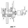
- the grading body separator (1) applies to mills for triturating and breaking up solids predispersed in liquids, such as the one represented in said figures, in this example for a mill which is the invention of the same applicant and which is the subject of European Patent Application No.
- a grinding chamber (8) is defined, in which the grinding bodies initially introduced into said chamber through a closeable inlet (9) of the stator are contained.
- an outlet (10) In the lower part of the stator (2) is an outlet (10), also closeable, for said grinding bodies, and the grinding chamber (8) is traversed by the product in treatment - while the rotor rotates - by conventional means (not shown) impelling said product, which are moved by drive means and through conventional transmission and speed variation means (not shown).
- the stator (2) has an inlet conduit (11) for the product to be treated, communicating with the exit of the product impulsion means and an outlet conduit (12) for the ground product, in whose exit zone the separator (1) is arranged which prevents the grinding bodies from leaving but lets the ground product pass.
- seal means are provided, such as joints (13) and (14), to prevent leakage of the product which circulates continuously and forcedly through the grinding chamber (8).
- the jacket (3) which may be made of two parts as in the example illustrated, has inlet lines (15), (16) and (17) for a cooling or heating fluid - the latter does not fully appear in figure 1A because of its position but part of its mouth leading to a cooling chamber (18) of the outlet conduit (12) of the ground product can be seen - and outlet conduits (19) and (20), all of which connect with the respective cooling or heating systems.
- the rotor (4) may be cooled or heated by pipes such as pipe (21), which feed the cooling or heating liquid into the interior of the rotor, the liquid returning through conduits such as (22); the pipes and conduits are connected to the respective internal lines (7) of shaft (5), which internal lines lead to the outside in a rotating coupling device (23) of shaft (5) connected to the cooling or heating system.
- pipes such as pipe (21)
- the pipes and conduits are connected to the respective internal lines (7) of shaft (5), which internal lines lead to the outside in a rotating coupling device (23) of shaft (5) connected to the cooling or heating system.
- the geometric axis of the type of mill described and illustrated is horizontal but could be vertical.
- the separator (1) is composed of a support (24) (figures 1A, 2 and 3) and a series of rings such as (25) (figures 1A, 4 and 5), which may consist of a variable number of rings, four in the example.
- the support (24) is stepped and preferably hollow; its ideal geometric envelope is a truncated cone and its steps consist of a series of circular rims (27) superposed along parallel planes, normal to the longitudinal axis (28) of the separator and of decreasing diameter from the major base (29) of the support to its free end or minor base (30).
- Said series of circular rims alternates with another series of short superposed circular cylinders (31), whose centers are disposed in said longitudinal axis (28) and whose diameters are also decreasing in coordination with the respective diameters of said rims (27).
- the major base (29) has a flange (32) and seal means for its installation in the respective mill, such as joint (33) (figure 1A) disposed in a circular groove (34) (figure 3), said installation being made in the exit zone of the ground product comprising a longitudinal passage (35) which opens into the outlet conduit (12) of the ground product.
- the stepped support (24) is fastened to the front part of the stator (2) by screws (36) which traversed orifices (37) in the flange (32) of the support (24), so that said flange (32) is on the outside of the mill while the rest of the support (24), together with its rings (25), are disposed toward the interior of the grinding chamber ( 8), as is seen in figure 1A.
- joints may, in some cases and must in others, be provided to assure watertightness between the support (24) of the separator (1) and the stator (2), as well as between the passage (35) of the support and the outlet conduit (12) of the ground product, and also in relation to the cooling chamber (18).
- orifices such as (38) which connect the cooling chamber (18) and the cooling chamber or chambers defined between the jackets (3) and the body of the stator (2).
- the mounting of the described separator (1) facilitates its disassembly without having to disassemble, in turn, the stator or the front part thereof.
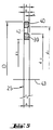
- the separator (1) is completed with a series of circular rings (25) of decreasing diameters from the major base (29) of the support (24) to the free end or minor base (30) of the latter, each of said rings being made up of an inner collar (39) and an outer collar (40) (figures 4 and 5), both of square cross section and interconnected by bridges such as (41), the latter defining, together with said two collars, respective transverse orifices or passages such as (42).
- Each ring (25) fits on a respective step (26), for which the inside diameter (d3 of its inner collar (39) matches, with the necessary fit, the outside diameter of the circular cylinder (31) of the step (26) on which it is mounted.
- the outside diameter (D) of the outer collar (40) of each of the rings that follow the largest of them coincides with the inside diameter (d1) of the outer collar (40) of the ring (25) on which it is juxtaposed, with the thickness (a) - measured in the direction of the longitudinal axis (28) of the support (24) of the separator (1) - of the inner collar (39) of a ring (25) being somewhat greater than the thickness (b) of its outer collar (40), thus causing a separation (c) between each pair of juxtaposed rings - in the direction of the coincident transverse axis (43) of the rings (25), which coincides with the axis (28) of the support (24) - which is smaller than the smallest of the thicknesses or diameters of the grinding bodies to be retained in the grinding chamber (8).
- the outer collar (40) of each of the rings that follow the largest of them defines a space, relative to the inner collar (39) of the ring (of greatest diameter D) on which it is juxtaposed, which is greater than said separation (c) between each pair of rings, that is to say, the inside diameter (d1) of the outer collar (40) of the ring of smaller diameter, which is juxtaposed to the following ring of greater diameter (see figure 1A) is greater than the outside diameter (d2) of the inner collar of said ring of greater diameter, establishing or defining between both rings and in this part thereof a circular separation which is greater than said also circular separation (c).
- a first circular collar (44) (figure 1A) of square cross section and of greater outside diameter than the diameter (D) of the largest ring (25) of the series of rings, the inside diameter of said first collar coinciding with the outside diameter (D) of the outer collar (40) of said largest ring.
- a kind of circular channel (46) is defined for the passage of the ground product toward the exit of the mill, which channel communicates with the longitudinal orifice or passage (35) that traverses the flange (32) of the support (24); and it should be pointed out that there may be more than one such longitudinal orifices (35), as needed in the operation of the mill.
- the first collar (44) is removably fastened to the support (24) by screws (47) which are screwed into threaded holes (48) (figures 2 and 3) of the support; and the assembly composed of the series of rings (25) and the second collar (45) is retained and immobilized by a disk (49) which is applied against the smallest ring and is removably fastened, (for example by a central screw), on the minor base (30) of the stepped support (24) of the separator (1), the outside diameter of said disk being equal to the inside diameter (d1) of the outer collar (40) of said smallest ring, while between the peripheral edge of this disk (49) and the opposite edge of said outer collar of the smallest ring a separation is defined equal to the separation (c) between each pair of juxtaposed rings.
- the section of the passages for retention of the grinding bodies is smaller than the section of the rest of the internal passages, thereby reducing the probability of any clogging or stopping up of the ground product occurring in this part of the separator.
Landscapes
- Engineering & Computer Science (AREA)
- Food Science & Technology (AREA)
- Crushing And Grinding (AREA)
Claims (4)
- Mahlkörper-Trenneinrichtung in Mühlen zum Zermahlen und Feinzerkleinern von in Flüssigkeiten dispergierten Feststoffen, enthaltend einen Rahmen, an dem ein festes Element oder Stator (2) befestigt ist, einen Mantel (3), der Kühl- oder Heizflüssigkeit führt, wobei der Stator (2) einen Rotor (4) einschließt, der auf einer Welle (5) befestigt ist, die längs der Längsachse der Mühle angeordnet ist und an entsprechenden Halte- und Lagereinrichtungen (6), die am Rahmen der Mühle befestigt sind, auskragend gehalten ist und die innere Leitungen (7) für Rotoren-Kühl- oder -Heizmedien aufweist und mittels Antriebseinrichtungen über am Rahmen befestigte Getriebe- und Geschwindigkeitsänderungseinrichtungen drehbar ist, wobei eine Mahlkammer (8) zwischen dem Stator (2) und dem Rotor (4) ausgebildet ist, in der Mahlkörper eingeschlossen sind, die zu Anfang in die Mahlkammer (8) durch einen schließbaren Einlaß (9) des Stators (2) eingeführt sind, und in dessen unteren Teil ein ebenfalls verschließbarer Auslaß (10) für ihren Abzug angeordnet ist, wobei die Mahlkammer (8) von dem in Behandlung befindlichen Produkt durchquert wird, während der Rotor (4) rotiert, der Stator (2) einen Einlaß (11) für das zu behandelnde Produkt und einen Auslaß (12) für das gemahlene Produkt aufweist, in dessen Auslaßzone Trenneinrichtungen (1) angeordnet sind, die verhindern, daß die Mahlkörper die Mühle verlassen, das gemahlene Produkt jedoch durchlassen, wobei Dichtungseinrichtungen (13, 14) zwischen dem Stator (2) und der Welle (5) angeordnet sind, um ein Entweichen des Produkts zu verhindern, das kontinuierlich und zwangsgefördert durch die Mahlkammer (8) zirkuliert, dadurch gekennzeichnet, daß sie einen abgestuften Träger (24) aufweist, dessen ideale geometrische Hülle ein Kegelstumpf ist, dessen Stufen durch eine Serie von kreisförmigen Ringflächen (27) gebildet sind, die längs paralleler Ebenen, die senkrecht zur Längsachse (28) der Trenneinrichtung (1) verlaufen, übereinander angeordnet sind und deren Durchmesser von der großen Basis (29) des Trägers (24) zu seinem freien Ende (30) hin abnehmen, welche Serie mit einer anderen Serie kurzer, kreisförmiger, übereinander angeordneter Zylinder (31) abwechselt, deren Zentren in der Längsachse (28) der Trenneinrichtung (1) liegen und deren Durchmesser ebenfalls in Koordinierung mit den jeweiligen Durchmessern der Ringflächen (27) abnehmen, wobei die große Basis (29) des Trägers (24) einen Flansch (32) und Dichtungseinrichtung (33) für ihren Einbau in der betreffenden Mühle in der Austrittszone des gemahlenen Produkts aufweist; daß sie eine Serie kreisförmiger Ringe (25) enthält mit Durchmessern, die von der größeren Basis (29) des Trägers zu dessen freien Ende (30) hin abnehmen, und die jeweils aus einem inneren Kragen (39) und einem äußeren Kragen (40) jeweils von quadratischem Querschnitt, die durch Brücken (41) miteinander verbunden sind, die jeweils Queröffnungen (42) begrenzen, bestehen, wobei jeder Ring (25) auf eine entsprechende Stufe (26) paßt, zu welchem Zweck der Innendurchmesser (d₃) seines inneren Kragens (39) mit dem Außendurchmesser des kreisförmigen Zylinders (31) der Stufe (26), auf der er montiert ist, übereinstimmt; daß der Außendurchmesser (D) des äußeren Kragens (40) eines jeden Rings (25), der dem größten von ihnen folgt, mit dem Innendurchmesser (d₁) des äußeren Kragens (40) des Rings (25), über dem er liegt, übereinstimmt, und daß die Dicke (a) - gemessen in Richtung der Längsachse (28) der Trenneinichtung (1) - des inneren Kragens (39) eines Rings (25) etwas größer als derjenige (b) seines äußeren Kragens (40) ist, was einen Spalt (c) zwischen jedem Paar benachbarter Ringe (25) in axialer Richtung verursacht, der kleiner ist, als das kleinste Dicken- oder Durchmessermaß der in der Mahlkammer (8) zurückzuhaltenden Mahlkörper; und daß der äußere Kragen (40) jedes Rings (25), der dem größten von ihnen folgt, einen Zwischenraum relativ zum inneren Kragen (39) des Rings (25), dem er benachbart ist, begrenzt, der größer als der Spalt (c) zwischen jedem Ringpaar (25) ist.
- Mahlkörpertrenneinrichtung nach Anspruch 1, bei der ein erster kreisförmiger Kragen (44) lösbar an der großen Basis (29) des Trägers (24) befestigt ist, wobei dieser erste kreisförmige Kragen (44) quadratischen Querschnitt aufweist und einen Außendurchmesser hat, der größer als jener (D) des größten aus der Ringserie (25) ist und dessen Innendurchmesser mit dem Außendurchmesser (D) des äußeren Kragens (40) des größten Rings (25) übereinstimmt.
- Schleifkörpertrenneinrichtung nach Anspruch 2, bei der in koplanarer und koaxialer Anordnung mit dem ersten kreisförmigen Kragen (44) ein ein zweiter kreisförmiger Kragen (45) ähnlich dem ersten (44), jedoch kleiner und praktisch gleich dem inneren Kragen (39) des größten Rings (25), über dem er liegt, angeordnet ist, wobei die Dicke dieses zweiten ringförmigen Kragens (45) - in axialer Richtung - etwas größer als jene (b) des äußeren Kragens (40) des genannten größten Rings (25) ist, was in axialer Richtung einen Zwischenraum zwischen den beiden schafft, der kleiner als das kleinste Dicken- oder Durchmessermaß der Mahlkörper ist, so daß zwischen den ersten und zweiten kreisförmigen Kragen (44, 45) eine Art Kanal (46) für den Durchlaß des gemahlenen Produkts in Richtung auf den Ausgang der Mühle durch wenigstens eine Längsöffnung (35) im Flansch (32) des Trägers (24) geschaffen ist.
- Schleifkörpertrenneinrichtung nach Anspruch 3, bei der die aus der Ringserie (25) und dem zweiten kreisförmigen Kragen (45) gebildete Anordnung mittels einer Scheibe (49) gehalten und festgelegt ist, die gegen den kleinsten Ring (25) drückt und lösbar an der kleineren Basis (30) des abgestuften Trägers (24) der Trenneinrichtung (1) befestigt ist, wobei der Außendurchmesser dieser Scheibe (49) gleich dem Innendurchmesser (d₁) des äußeren Kragens (40) des kleinsten Rings (25) ist und zwischen dem Umfangsrand dieser Scheibe (49) und dem gegenüberliegenden Rand des äußeren Kragens (40) des kleinsten Rings (25) ein Zwischenraum ausgebildet ist, der gleich jenem (c) zwischen jedem Paar übereinander angeordneter Ringe (25) ist.
Applications Claiming Priority (2)
| Application Number | Priority Date | Filing Date | Title |
|---|---|---|---|
| ES9002767A ES2030619A6 (es) | 1990-10-31 | 1990-10-31 | Separador de cuerpos moledores en molinos para triturar y desaglomerar solidos predispersados en liquidos. |
| ES9002767 | 1990-10-31 |
Publications (2)
| Publication Number | Publication Date |
|---|---|
| EP0483452A1 EP0483452A1 (de) | 1992-05-06 |
| EP0483452B1 true EP0483452B1 (de) | 1995-08-30 |
Family
ID=8269414
Family Applications (1)
| Application Number | Title | Priority Date | Filing Date |
|---|---|---|---|
| EP91109306A Expired - Lifetime EP0483452B1 (de) | 1990-10-31 | 1991-06-06 | Mahlkörper-Trenneinrichtung für Mühlen zum Zermahlen und Feinzerkleinern von in Flüssigkeiten dispergierten Feststoffen |
Country Status (5)
| Country | Link |
|---|---|
| US (1) | US5114080A (de) |
| EP (1) | EP0483452B1 (de) |
| JP (1) | JPH04243555A (de) |
| DE (1) | DE69112567D1 (de) |
| ES (1) | ES2030619A6 (de) |
Families Citing this family (6)
| Publication number | Priority date | Publication date | Assignee | Title |
|---|---|---|---|---|
| ES2031788A6 (es) * | 1991-06-27 | 1992-12-16 | Oliver & Battle Sa | Mejoras en el objeto de la patente principal n{ 9002767 por separador de cuerpos moledores, en molinos para triturar y desaglomerar solidos predispersados en liquidos. |
| ES2031789A6 (es) * | 1991-06-27 | 1992-12-16 | Oliver & Battle Sa | Mejoras en el objeto de la patente principal n{ 9002766 por molino para triturar y desaglomerar solidos predispersados en liquidos. |
| US5785262A (en) * | 1997-03-13 | 1998-07-28 | Tippett; Jerome P. | Apparatus FPR dispersing finely divided solid particles in a liquid vehicle |
| JP3972179B2 (ja) * | 2002-02-06 | 2007-09-05 | ターボ工業株式会社 | ビーズミル |
| WO2004071666A1 (en) * | 2003-02-07 | 2004-08-26 | King Machine And Tool Co. | Improved disc mill assembly for pulverizing system |
| CN106000555B (zh) * | 2016-05-31 | 2018-06-15 | 连云港海蓝研磨材料有限公司 | 一种晶体微粉的连续出料球磨工艺 |
Family Cites Families (8)
| Publication number | Priority date | Publication date | Assignee | Title |
|---|---|---|---|---|
| US1185794A (en) * | 1915-08-05 | 1916-06-06 | Improved Paper Machinery Company | Paper machinery. |
| ES449976A1 (es) * | 1976-07-20 | 1977-08-16 | Oliver & Battle Sa | Perfeccionamientos en molinos de eje horizontal refrigera- dos, para productos predispersados de solidos en liquidos. |
| DE3345680A1 (de) * | 1983-12-16 | 1985-06-20 | Gebrüder Netzsch, Maschinenfabrik GmbH & Co, 8672 Selb | Ruehrwerksmuehle |
| US4651935A (en) * | 1984-10-19 | 1987-03-24 | Morehouse Industries, Inc. | Horizontal media mill |
| US4709863A (en) * | 1985-10-04 | 1987-12-01 | Morehouse Industries, Inc. | Media mill screen assembly |
| DE8610329U1 (de) * | 1986-04-16 | 1987-07-09 | Draiswerke Gmbh, 6800 Mannheim | Geschlossene Rührwerksmühle und Trenneinrichtung für geschlossene Rührwerksmühle |
| DE3716295A1 (de) * | 1987-05-15 | 1988-11-24 | Fryma Maschinenbau Gmbh | Spalt-kugelmuehle zum kontinuierlichen feinzerkleinern, insbesondere aufschliessen von mikroorganismen und dispergieren von feststoffen in fluessigkeit |
| SE463215B (sv) * | 1989-02-22 | 1990-10-22 | Kamyr Ab | Apparat foer silning av en suspension av ett fiberhaltigt cellulosamaterial |
-
1990
- 1990-10-31 ES ES9002767A patent/ES2030619A6/es not_active Expired - Lifetime
-
1991
- 1991-06-06 EP EP91109306A patent/EP0483452B1/de not_active Expired - Lifetime
- 1991-06-06 DE DE69112567T patent/DE69112567D1/de not_active Expired - Lifetime
- 1991-06-19 US US07/718,350 patent/US5114080A/en not_active Expired - Fee Related
- 1991-06-28 JP JP3158588A patent/JPH04243555A/ja active Pending
Also Published As
| Publication number | Publication date |
|---|---|
| US5114080A (en) | 1992-05-19 |
| ES2030619A6 (es) | 1992-11-01 |
| DE69112567D1 (de) | 1995-10-05 |
| JPH04243555A (ja) | 1992-08-31 |
| EP0483452A1 (de) | 1992-05-06 |
Similar Documents
| Publication | Publication Date | Title |
|---|---|---|
| US3844490A (en) | Apparatus for dispersing finely divided solid particles in a liquid vehicle | |
| US7014134B2 (en) | Stirred ball mill | |
| DE69328944T2 (de) | Apparat zur Verarbeitung von körnigem Material | |
| US3653600A (en) | Apparatus for dispersing finely divided solid particles in a liquid vehicle | |
| US5531385A (en) | Apparatus and methods for wet grinding | |
| US5193754A (en) | Mill for triturating and breaking up solids predispersed in liquids | |
| EP2106859A2 (de) | Medienmischmühle | |
| US4513917A (en) | Sand mill rotor discs | |
| EP0913200B1 (de) | Rührwerksmühle | |
| DE10011579A1 (de) | Rührwerksmühle | |
| US3845938A (en) | Apparatus for dispersing finely divided solid particles in a liquid vehicle | |
| CA1330205C (en) | Apparatus for screening a suspension of fibrous cellulose pulp | |
| US5114080A (en) | Grinding body separator in mills for triturating and breaking up solids predispersed in liquids | |
| DE3716295A1 (de) | Spalt-kugelmuehle zum kontinuierlichen feinzerkleinern, insbesondere aufschliessen von mikroorganismen und dispergieren von feststoffen in fluessigkeit | |
| EP1534435A1 (de) | Rührwerkskugelmühle mit radialrührwerk | |
| US5785262A (en) | Apparatus FPR dispersing finely divided solid particles in a liquid vehicle | |
| US4582266A (en) | Centrifugal media mill | |
| US4394981A (en) | Apparatus for dispersing finely divided solid particles in a liquid vehicle with a mechanism for reducing screen clogging | |
| JPH10230182A (ja) | 粉砕機 | |
| DE3040706C2 (de) | ||
| US4746069A (en) | Centrifugal media mill | |
| US3685749A (en) | Sandmill vessel | |
| DE102021101527B4 (de) | Rührwerksmühle | |
| KR940004229B1 (ko) | 충격식 분리기 | |
| DE19614295A1 (de) | Verfahren und Vorrichtung zum Nassmahlen und Dispergieren von Feststoffpartikeln in Flüssigkeiten |
Legal Events
| Date | Code | Title | Description |
|---|---|---|---|
| PUAI | Public reference made under article 153(3) epc to a published international application that has entered the european phase |
Free format text: ORIGINAL CODE: 0009012 |
|
| AK | Designated contracting states |
Kind code of ref document: A1 Designated state(s): BE DE FR GB IT NL |
|
| 17P | Request for examination filed |
Effective date: 19920522 |
|
| 17Q | First examination report despatched |
Effective date: 19930420 |
|
| GRAA | (expected) grant |
Free format text: ORIGINAL CODE: 0009210 |
|
| AK | Designated contracting states |
Kind code of ref document: B1 Designated state(s): BE DE FR GB IT NL |
|
| PG25 | Lapsed in a contracting state [announced via postgrant information from national office to epo] |
Ref country code: IT Free format text: LAPSE BECAUSE OF FAILURE TO SUBMIT A TRANSLATION OF THE DESCRIPTION OR TO PAY THE FEE WITHIN THE PRE;WARNING: LAPSES OF ITALIAN PATENTS WITH EFFECTIVE DATE BEFORE 2007 MAY HAVE OCCURRED AT ANY TIME BEFORE 2007. THE CORRECT EFFECTIVE DATE MAY BE DIFFERENT FROM THE ONE RECORDED.SCRIBED TIME-LIMIT Effective date: 19950830 Ref country code: BE Effective date: 19950830 Ref country code: NL Free format text: LAPSE BECAUSE OF FAILURE TO SUBMIT A TRANSLATION OF THE DESCRIPTION OR TO PAY THE FEE WITHIN THE PRESCRIBED TIME-LIMIT Effective date: 19950830 Ref country code: FR Free format text: THE PATENT HAS BEEN ANNULLED BY A DECISION OF A NATIONAL AUTHORITY Effective date: 19950830 |
|
| REF | Corresponds to: |
Ref document number: 69112567 Country of ref document: DE Date of ref document: 19951005 |
|
| PG25 | Lapsed in a contracting state [announced via postgrant information from national office to epo] |
Ref country code: DE Effective date: 19951201 |
|
| EN | Fr: translation not filed | ||
| NLV1 | Nl: lapsed or annulled due to failure to fulfill the requirements of art. 29p and 29m of the patents act | ||
| PG25 | Lapsed in a contracting state [announced via postgrant information from national office to epo] |
Ref country code: GB Effective date: 19960606 |
|
| PLBE | No opposition filed within time limit |
Free format text: ORIGINAL CODE: 0009261 |
|
| STAA | Information on the status of an ep patent application or granted ep patent |
Free format text: STATUS: NO OPPOSITION FILED WITHIN TIME LIMIT |
|
| 26N | No opposition filed | ||
| GBPC | Gb: european patent ceased through non-payment of renewal fee |
Effective date: 19960606 |