EP0483496B1 - Dispositif pour suspendre ou ranger des vêtements - Google Patents
Dispositif pour suspendre ou ranger des vêtements Download PDFInfo
- Publication number
- EP0483496B1 EP0483496B1 EP91115423A EP91115423A EP0483496B1 EP 0483496 B1 EP0483496 B1 EP 0483496B1 EP 91115423 A EP91115423 A EP 91115423A EP 91115423 A EP91115423 A EP 91115423A EP 0483496 B1 EP0483496 B1 EP 0483496B1
- Authority
- EP
- European Patent Office
- Prior art keywords
- holder
- carrier arm
- rods
- bent
- jutting
- Prior art date
- Legal status (The legal status is an assumption and is not a legal conclusion. Google has not performed a legal analysis and makes no representation as to the accuracy of the status listed.)
- Revoked
Links
- 230000008878 coupling Effects 0.000 claims abstract description 13
- 238000010168 coupling process Methods 0.000 claims abstract description 13
- 238000005859 coupling reaction Methods 0.000 claims abstract description 13
- 230000002787 reinforcement Effects 0.000 claims description 3
- 239000013013 elastic material Substances 0.000 claims description 2
- 238000001746 injection moulding Methods 0.000 claims description 2
- 239000011248 coating agent Substances 0.000 claims 2
- 238000000576 coating method Methods 0.000 claims 2
- 238000004026 adhesive bonding Methods 0.000 claims 1
- 229920002994 synthetic fiber Polymers 0.000 claims 1
- 230000001419 dependent effect Effects 0.000 description 1
- 239000000725 suspension Substances 0.000 description 1
Images

Classifications
-
- A—HUMAN NECESSITIES
- A47—FURNITURE; DOMESTIC ARTICLES OR APPLIANCES; COFFEE MILLS; SPICE MILLS; SUCTION CLEANERS IN GENERAL
- A47B—TABLES; DESKS; OFFICE FURNITURE; CABINETS; DRAWERS; GENERAL DETAILS OF FURNITURE
- A47B61/00—Wardrobes
- A47B61/02—Wardrobes with extensible garment-holders
-
- A—HUMAN NECESSITIES
- A47—FURNITURE; DOMESTIC ARTICLES OR APPLIANCES; COFFEE MILLS; SPICE MILLS; SUCTION CLEANERS IN GENERAL
- A47G—HOUSEHOLD OR TABLE EQUIPMENT
- A47G25/00—Household implements used in connection with wearing apparel; Dress, hat or umbrella holders
- A47G25/02—Dress holders; Dress suspending devices; Clothes-hanger assemblies; Clothing lifters
- A47G25/06—Clothes hooks; Clothes racks; Garment-supporting stands with swingable or extending arms
- A47G25/0685—Collapsible clothes racks, e.g. swingable, foldable, extendible
Definitions
- the invention relates to a device for hanging or storing clothes, in particular pants and ties, which can be screwed or glued to the inside of a side wall of a furniture body, with a holder for better removal of the clothes in a holder attached to the side wall of the furniture body around a horizontal Axis pivotally arranged along the side wall support arm and a rod projecting from its end in the pivot axis direction for receiving the clothing.
- a device for hanging and storing clothes is known from utility model DE-U-85 30 985.5.
- a lower and an upper running rail are fixedly arranged, preferably screwed, on the inner wall of a furniture body.
- the lower and upper sides of a rectangular frame with the hangers, brackets and storage trays used for hanging or storage are guided in these rails.
- the rectangular frame is attached to the inside of a cabinet, it is partially outside the cabinet after being pulled out, which makes it easier to access. To achieve accessibility, the frame must be moved on the rails. This presupposes that the rails are mounted exactly in the specified parallel position and that they are easy to pull out is guaranteed.
- the targeted storage of several hanging clothes e.g. B. pants or ties, is not possible.
- GB-A-22 20 136 there is also already known a hanging device for clothes, in which a support arm which is pivotable along the side wall about a horizontal axis is arranged in a holder fastened to the side wall of a furniture body, at the end of which a rod projecting in the pivot axis direction is appropriate.
- GB-A-308 046 and GB-A-337 120 describe hanging devices for garments in which a support arm can be pivoted horizontally out of the furniture body via a two-part steering linkage or can be pivoted out about a horizontal axis along the side wall of the furniture body Support arm horizontal, but laterally pivotable rods are arranged for receiving the items of clothing.
- the present invention has for its object to provide both a hanging and a storage option for the clothes and also to allow easy access to the hanging clothes, the device should be simple and easy to operate.
- the support arm is formed by two mutually parallel spaced and pivotally arranged on the holder in the form of a parallelogram support arm elements which are connected directly or indirectly articulated to cross bars with their projecting ends, being perpendicular to these cross bars a plurality of rods connected to form a rigid unit and projecting in the swivel axis direction are fastened.
- a device is thus provided, the support arm of which, together with the projecting rods forming a rigid unit, is designed as an articulated parallelogram, the rigid support and storage unit being fastened to a bracket articulated on the support arm elements.
- bars arranged in one plane are located horizontally in every pivoting position of the support arm and can be used equally for hanging and for storage.
- the parallelogram-like swivel mechanism in which the rigid rod unit is integrated the device is of uncomplicated design, not susceptible to faults and easy to handle.
- the storage option is also ensured by the rigid arrangement of the projecting rods, the latter - together with the swiveling ability - at the same time ensures good access to the garments.
- a coupling piece is permanently arranged at the ends of the elements of the support arm, which coupling piece consist of plastic and can be produced by injection molding.
- the bracket is articulated with its angled ends in the corresponding coupling pieces of the elements of the support arm.
- the width of the bracket corresponds to the width of the holder and the distance between the parallel elements of the support arm.
- the holder can have a U-shape with angled ends of the webs. On these bends, a coupling piece of the elements of the support arm is advantageously articulated.
- the length of the cantilevered rods for receiving trousers is much greater than for accepting ties.
- the interchangeable arrangement of the additional stop ring, by means of which the angle of the pivoting in each case can be additionally limited in one direction, is particularly advantageous. Since the device according to the invention can be attached to both the right and the left side wall of a furniture body can, to prevent the device from striking the rear wall, the stop ring is additionally attached to the side of the holder which faces the rear wall.
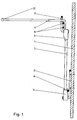
- a U-shaped holder 2 is screwed onto the side wall 1 of a furniture body, preferably a cabinet. The ends of the webs of this holder 2 are angled pointing away from the side wall.
- a support arm 3 formed from two mutually parallel elements is pivotally mounted, at the upper end of which a carrier intended for receiving the items of clothing in the form of projecting parallel rods 4 is arranged.
- a coupling piece 5 made of plastic is fixedly arranged, which serve as a joint and via which the pivoting movements of the carrier consisting of the projecting rods 4 can be carried out.
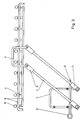
- the cantilevered rods 4 are connected at one end to a rigid unit via transverse rods 6 running at right angles thereto, the rods 4 being rigidly connected to the transverse rods 6 with an angle.
- the cross bars 6 are in turn connected to a U-shaped bracket 7, the webs of which are angled at the end. These angled ends are articulated in the corresponding coupling pieces 5 of the elements of the support arm 3.
- On the other side of the support arm 3, its parallel elements are articulated with their fixed coupling pieces 5 on the bends of the webs of the holder 2.
- the prerequisite for this is that the width of the bracket 7 corresponds to the width of the holder 2 and in the distance between the parallel elements of the support arm 3.
- Stop brackets 8 for the pivotable support arm 3 are arranged on the holder 2.
- the stop limits 8 are formed by angled portions of a web arranged vertically on the holder 2 that point toward the support arm 3.
- An additional interchangeable stop ring 9 can be pushed onto the stop limits 8.
- the free ends of the projecting rods 4 have a reinforcement 10. This will strip the put on clothing difficult.
- the surfaces of the cantilevered bars 4 can be provided with a profile, expediently with a non-slip covering in the form of a shrunk-on hose made of elastic material.
Landscapes
- Holders For Apparel And Elements Relating To Apparel (AREA)
- Supports Or Holders For Household Use (AREA)
- Bathtubs, Showers, And Their Attachments (AREA)
Claims (18)
- Dispositif pour suspendre ou déposer des pièces de vêtement, en particulier des pantalons ou des cravates, fixé par vissage ou collage sur la face interne d'une paroi latérale (1) du corps d'un meuble, comprenant un support (2) le long de la paroi latérale, un bras porteur (3) monté sur le support (2) et pouvant basculer le long de la paroi latérale (1) autour d'un axe horizontal, une tige (4) située à l'extrémité du bras porteur débordant en direction de l'axe de basculement et servant à recevoir les pièces de vêtement, le dispositif, pour faciliter la prise du vêtement, pouvant être tiré à l'extérieur du corps du meuble, caractérisé en ce que le bras porteur (3) est constitué de deux éléments parallèles espacés, montés basculants sur le support (2) en formant un parallélogramme, tandis que les extrémités des éléments éloignées du support sont articulées directement ou indirectement à des barres transversales (6) sur lesquelles sont fixées, perpendiculairement à elles, plusieurs tiges débordantes, parallèles à l'axe de basculement, constituant un ensemble rigide.
- Dispositif selon la revendication 1, caractérisé en ce que les extrémités libres des tiges débordantes (4) présentent un renforcement (10).
- Dispositif selon la revendication 1 ou 2, caractérisé en ce que chacune des tiges débordantes (4) est raccordée aux barres transversales (6) par une extrémité coudée à la verticale.
- Dispositif selon l'une des revendications 1 à 3, caractérisé en ce que les barres transversales (6) sont fixées à un étrier (7).
- Dispositif selon l'une des revendications 1 à 3, caractérisé en ce que l'étrier (7) a la forme d'un U dont les branches sont coudées, à leurs extrémités, en direction de l'axe de basculement.
- Dispositif selon la revendication 1, caractérisé en ce que chacune des extrémités des éléments du bras porteur (3) est munie d'une pièce d'accouplement.
- Dispositif selon la revendication 1 ou une des revendications 4 à 6, caractérisé en ce que l'étrier (7) est articulé dans les pièces d'accouplement, par ses extrémités coudées.
- Dispositif selon l'une des revendications 1 à 7, caractérisé en ce que la largeur de l'étier (7) correspond à celle du support (2) et à l'intervalle séparant les éléments parallèles constituant le bras porteur (3).
- Dispositif selon l'une des revendications 1 à 8, caractérisé en ce que le support (2) a la forme d'un U dont les branches sont coudées, à leurs extrémités, parallèlement à l'axe de basculement du bras porteur.
- Dispositif selon l'une des revendications 1 à 9, caractérisé en ce que chacune des extrémités coudées des branches du support (2) constitue une articulation portant une pièce d'accouplement (5) d'un élément du bras porteur (3).
- Dispositif selon l'une des revendications 1 à 10, caractérisé en ce que des butées de limitation (8) sont fixées au support (2) pour le basculement du bras porteur (3).
- Dispositif selon la revendication 1, caractérisé en ce que les butées de limitation (8) sont constituées par des parties coudées, en direction du bras porteur (3), d'une barre montée perpendiculairement sur le support (2).
- Dispositif selon la revendication 11 ou 12, caractérisé en ce qu'on peut monter, par coulissement, une bague additionnelle de butée (9) sur chaque extrémité coudée, servant de butée de la limitation (8) de la barre.
- Dispositif selon la revendication 13, caractérisé en ce que la bague de butée (9) et amovible.
- Dispositif selon l'une des revendications 1 à 14, caractérisé en ce que la face supérieure des tiges débordantes (4) est profilée.
- Dispositif selon l'une des revendications 1 à 15, caractérisé en ce que les tiges débordantes (4) porte un revêtement antiglissant.
- Dispositif selon la revendication 16, caractérisé en ce que le revêtement antiglissant est constitué par un manchon en matériau élastique.
- Dispositif selon l'une des revendications 1 à 17, caractérisé en ce que les pièces d'accouplement (5) sont réalisées en matière plastique, par injection.
Applications Claiming Priority (2)
| Application Number | Priority Date | Filing Date | Title |
|---|---|---|---|
| DE9015070U | 1990-11-02 | ||
| DE9015070U DE9015070U1 (de) | 1990-11-02 | 1990-11-02 | Vorrichtung zum Aufhängen oder zur Ablage von Kleidungsstücken |
Publications (2)
| Publication Number | Publication Date |
|---|---|
| EP0483496A1 EP0483496A1 (fr) | 1992-05-06 |
| EP0483496B1 true EP0483496B1 (fr) | 1994-06-29 |
Family
ID=6858950
Family Applications (1)
| Application Number | Title | Priority Date | Filing Date |
|---|---|---|---|
| EP91115423A Revoked EP0483496B1 (fr) | 1990-11-02 | 1991-09-12 | Dispositif pour suspendre ou ranger des vêtements |
Country Status (3)
| Country | Link |
|---|---|
| EP (1) | EP0483496B1 (fr) |
| AT (1) | ATE107841T1 (fr) |
| DE (2) | DE9015070U1 (fr) |
Family Cites Families (5)
| Publication number | Priority date | Publication date | Assignee | Title |
|---|---|---|---|---|
| GB147619A (en) * | 1919-06-06 | 1921-05-19 | Alfred Kunz | Improvements in or relating to arch construction, particularly for tunnel framework |
| GB308046A (en) * | 1928-02-15 | 1929-03-21 | James Everitt | Fittings for hanging garments in wardrobes and the like |
| GB337120A (en) * | 1929-09-05 | 1930-10-30 | Samuel Timings | Improvements in garment supporting devices |
| GB727416A (en) * | 1952-03-21 | 1955-03-30 | John Siddons Corby | Improvements in or relating to tie racks |
| US5011029A (en) * | 1988-06-30 | 1991-04-30 | Sugatsune Industrial Co., Ltd. | Coat lift hanger |
-
1990
- 1990-11-02 DE DE9015070U patent/DE9015070U1/de not_active Expired - Lifetime
-
1991
- 1991-09-12 AT AT91115423T patent/ATE107841T1/de not_active IP Right Cessation
- 1991-09-12 DE DE59102071T patent/DE59102071D1/de not_active Revoked
- 1991-09-12 EP EP91115423A patent/EP0483496B1/fr not_active Revoked
Non-Patent Citations (1)
| Title |
|---|
| GB A 1 476 AD 1911 * |
Also Published As
| Publication number | Publication date |
|---|---|
| EP0483496A1 (fr) | 1992-05-06 |
| DE9015070U1 (de) | 1991-01-24 |
| ATE107841T1 (de) | 1994-07-15 |
| DE59102071D1 (de) | 1994-08-04 |
Similar Documents
| Publication | Publication Date | Title |
|---|---|---|
| DE2224327C3 (de) | Schrankmöbel mit wahlweiser Anordnung einer Rolljalousie oder einer Schwenktür | |
| EP0339053B1 (fr) | Porte-vetements multiple articule | |
| DE4330867C1 (de) | Ausziehbares Einbaubügelbrett | |
| DE2904616C2 (de) | Vorrichtung zum Offenhalten einer schwenkbar angelenkten Tür eines Kraftfahrzeugs | |
| DE8908193U1 (de) | Schwenkbarer Mehrfachkleiderbügel mit Führungsschiene | |
| EP0522246B1 (fr) | Séchoir à linge avec un dispositif de fixation | |
| EP0483496B1 (fr) | Dispositif pour suspendre ou ranger des vêtements | |
| EP0452674B1 (fr) | Chariot de nettoyage | |
| DE202015104085U1 (de) | An einen Fahrrad-Gepäckträger anschließbares Gepäckstück | |
| DE202015105816U1 (de) | Transportwagen | |
| DE102006055404A1 (de) | Kleiderhalter für ein Kraftfahrzeug | |
| DE4416237A1 (de) | Abfallsammler | |
| DE1460827A1 (de) | Waeschetrockner | |
| DE4225937A1 (de) | Wäschesackständer | |
| EP0577113B1 (fr) | Cintre avec élément transversal démontable | |
| DE2838285A1 (de) | Aufhaengevorrichtung zur befestigung an waenden, insbesondere wandregal | |
| DE3207806A1 (de) | Vorrichtung zum aufhaengen von gegenstaenden, insbesondere von schuhen | |
| AT376627B (de) | Einrichtung zur halterung mindestens einer ankuendigungstafel | |
| DE19845492C2 (de) | Aufhängevorrichtung | |
| DE8702792U1 (de) | Wäschesammler | |
| DE1958508U (de) | Aufhaenger zum trocknen von waesche. | |
| DE3444256A1 (de) | Stapelbarer einkaufswagen | |
| DE2221430A1 (de) | Kombinierter bettnachttisch | |
| DE202021002618U1 (de) | Befestigungsmittel für eine Rückwand an einem Rollbehälter | |
| DE4445675A1 (de) | Schuhtragbügel |
Legal Events
| Date | Code | Title | Description |
|---|---|---|---|
| PUAI | Public reference made under article 153(3) epc to a published international application that has entered the european phase |
Free format text: ORIGINAL CODE: 0009012 |
|
| AK | Designated contracting states |
Kind code of ref document: A1 Designated state(s): AT BE CH DE FR LI LU NL |
|
| 17P | Request for examination filed |
Effective date: 19921005 |
|
| 17Q | First examination report despatched |
Effective date: 19931014 |
|
| GRAA | (expected) grant |
Free format text: ORIGINAL CODE: 0009210 |
|
| AK | Designated contracting states |
Kind code of ref document: B1 Designated state(s): AT BE CH DE FR LI LU NL |
|
| REF | Corresponds to: |
Ref document number: 107841 Country of ref document: AT Date of ref document: 19940715 Kind code of ref document: T |
|
| ET | Fr: translation filed | ||
| REF | Corresponds to: |
Ref document number: 59102071 Country of ref document: DE Date of ref document: 19940804 |
|
| PLBI | Opposition filed |
Free format text: ORIGINAL CODE: 0009260 |
|
| 26 | Opposition filed |
Opponent name: EBB BESCHLAGTECHNIK GMBH Effective date: 19950116 |
|
| NLR1 | Nl: opposition has been filed with the epo |
Opponent name: EBB BESCHLAGTECHNIK GMBH |
|
| PGFP | Annual fee paid to national office [announced via postgrant information from national office to epo] |
Ref country code: LU Payment date: 19960901 Year of fee payment: 6 |
|
| PGFP | Annual fee paid to national office [announced via postgrant information from national office to epo] |
Ref country code: AT Payment date: 19960912 Year of fee payment: 6 |
|
| PGFP | Annual fee paid to national office [announced via postgrant information from national office to epo] |
Ref country code: NL Payment date: 19960930 Year of fee payment: 6 Ref country code: FR Payment date: 19960930 Year of fee payment: 6 |
|
| PGFP | Annual fee paid to national office [announced via postgrant information from national office to epo] |
Ref country code: BE Payment date: 19961010 Year of fee payment: 6 |
|
| PGFP | Annual fee paid to national office [announced via postgrant information from national office to epo] |
Ref country code: DE Payment date: 19961129 Year of fee payment: 6 |
|
| PGFP | Annual fee paid to national office [announced via postgrant information from national office to epo] |
Ref country code: CH Payment date: 19961216 Year of fee payment: 6 |
|
| PG25 | Lapsed in a contracting state [announced via postgrant information from national office to epo] |
Ref country code: LU Free format text: LAPSE BECAUSE OF NON-PAYMENT OF DUE FEES Effective date: 19970912 |
|
| RDAH | Patent revoked |
Free format text: ORIGINAL CODE: EPIDOS REVO |
|
| RDAG | Patent revoked |
Free format text: ORIGINAL CODE: 0009271 |
|
| STAA | Information on the status of an ep patent application or granted ep patent |
Free format text: STATUS: PATENT REVOKED |
|
| REG | Reference to a national code |
Ref country code: CH Ref legal event code: PL |
|
| 27W | Patent revoked |
Effective date: 19971120 |
|
| NLV4 | Nl: lapsed or anulled due to non-payment of the annual fee |
Effective date: 19980401 |