EP0483524A1 - Verfahren und Vorrichtung für die Wasserreinigung - Google Patents
Verfahren und Vorrichtung für die Wasserreinigung Download PDFInfo
- Publication number
- EP0483524A1 EP0483524A1 EP91116580A EP91116580A EP0483524A1 EP 0483524 A1 EP0483524 A1 EP 0483524A1 EP 91116580 A EP91116580 A EP 91116580A EP 91116580 A EP91116580 A EP 91116580A EP 0483524 A1 EP0483524 A1 EP 0483524A1
- Authority
- EP
- European Patent Office
- Prior art keywords
- fluid
- cells
- cell
- passageway
- separator
- Prior art date
- Legal status (The legal status is an assumption and is not a legal conclusion. Google has not performed a legal analysis and makes no representation as to the accuracy of the status listed.)
- Withdrawn
Links
- XLYOFNOQVPJJNP-UHFFFAOYSA-N water Substances O XLYOFNOQVPJJNP-UHFFFAOYSA-N 0.000 title description 6
- 238000005352 clarification Methods 0.000 title 1
- 238000000034 method Methods 0.000 title 1
- 239000012530 fluid Substances 0.000 claims abstract description 57
- 238000005188 flotation Methods 0.000 claims abstract description 10
- 238000000926 separation method Methods 0.000 claims abstract description 10
- 238000005273 aeration Methods 0.000 claims abstract description 9
- 230000005484 gravity Effects 0.000 claims description 3
- 239000007788 liquid Substances 0.000 claims description 3
- 238000004891 communication Methods 0.000 claims description 2
- 238000007599 discharging Methods 0.000 claims description 2
- 238000011144 upstream manufacturing Methods 0.000 claims 2
- 230000000977 initiatory effect Effects 0.000 claims 1
- 238000005086 pumping Methods 0.000 claims 1
- 239000000356 contaminant Substances 0.000 abstract description 10
- 238000004140 cleaning Methods 0.000 abstract description 3
- 230000000712 assembly Effects 0.000 abstract description 2
- 238000000429 assembly Methods 0.000 abstract description 2
- 239000007787 solid Substances 0.000 description 8
- 239000006260 foam Substances 0.000 description 5
- 239000002245 particle Substances 0.000 description 2
- 239000010802 sludge Substances 0.000 description 2
- 238000010276 construction Methods 0.000 description 1
- 238000011835 investigation Methods 0.000 description 1
- 239000000463 material Substances 0.000 description 1
- 235000013372 meat Nutrition 0.000 description 1
- 238000012986 modification Methods 0.000 description 1
- 230000004048 modification Effects 0.000 description 1
- 238000012856 packing Methods 0.000 description 1
- 238000009428 plumbing Methods 0.000 description 1
- 239000002699 waste material Substances 0.000 description 1
Images



Classifications
-
- B—PERFORMING OPERATIONS; TRANSPORTING
- B03—SEPARATION OF SOLID MATERIALS USING LIQUIDS OR USING PNEUMATIC TABLES OR JIGS; MAGNETIC OR ELECTROSTATIC SEPARATION OF SOLID MATERIALS FROM SOLID MATERIALS OR FLUIDS; SEPARATION BY HIGH-VOLTAGE ELECTRIC FIELDS
- B03D—FLOTATION; DIFFERENTIAL SEDIMENTATION
- B03D1/00—Flotation
- B03D1/14—Flotation machines
- B03D1/1418—Flotation machines using centrifugal forces
-
- B—PERFORMING OPERATIONS; TRANSPORTING
- B01—PHYSICAL OR CHEMICAL PROCESSES OR APPARATUS IN GENERAL
- B01D—SEPARATION
- B01D17/00—Separation of liquids, not provided for elsewhere, e.g. by thermal diffusion
- B01D17/02—Separation of non-miscible liquids
- B01D17/0205—Separation of non-miscible liquids by gas bubbles or moving solids
-
- B—PERFORMING OPERATIONS; TRANSPORTING
- B01—PHYSICAL OR CHEMICAL PROCESSES OR APPARATUS IN GENERAL
- B01D—SEPARATION
- B01D17/00—Separation of liquids, not provided for elsewhere, e.g. by thermal diffusion
- B01D17/02—Separation of non-miscible liquids
- B01D17/0208—Separation of non-miscible liquids by sedimentation
- B01D17/0214—Separation of non-miscible liquids by sedimentation with removal of one of the phases
-
- B—PERFORMING OPERATIONS; TRANSPORTING
- B01—PHYSICAL OR CHEMICAL PROCESSES OR APPARATUS IN GENERAL
- B01D—SEPARATION
- B01D21/00—Separation of suspended solid particles from liquids by sedimentation
- B01D21/003—Sedimentation tanks provided with a plurality of compartments separated by a partition wall
-
- B—PERFORMING OPERATIONS; TRANSPORTING
- B01—PHYSICAL OR CHEMICAL PROCESSES OR APPARATUS IN GENERAL
- B01D—SEPARATION
- B01D21/00—Separation of suspended solid particles from liquids by sedimentation
- B01D21/0093—Mechanisms for taking out of action one or more units of a multi-unit settling mechanism
-
- B—PERFORMING OPERATIONS; TRANSPORTING
- B01—PHYSICAL OR CHEMICAL PROCESSES OR APPARATUS IN GENERAL
- B01D—SEPARATION
- B01D21/00—Separation of suspended solid particles from liquids by sedimentation
- B01D21/24—Feed or discharge mechanisms for settling tanks
- B01D21/2433—Discharge mechanisms for floating particles
-
- B—PERFORMING OPERATIONS; TRANSPORTING
- B01—PHYSICAL OR CHEMICAL PROCESSES OR APPARATUS IN GENERAL
- B01D—SEPARATION
- B01D21/00—Separation of suspended solid particles from liquids by sedimentation
- B01D21/26—Separation of sediment aided by centrifugal force or centripetal force
-
- B—PERFORMING OPERATIONS; TRANSPORTING
- B03—SEPARATION OF SOLID MATERIALS USING LIQUIDS OR USING PNEUMATIC TABLES OR JIGS; MAGNETIC OR ELECTROSTATIC SEPARATION OF SOLID MATERIALS FROM SOLID MATERIALS OR FLUIDS; SEPARATION BY HIGH-VOLTAGE ELECTRIC FIELDS
- B03D—FLOTATION; DIFFERENTIAL SEDIMENTATION
- B03D1/00—Flotation
- B03D1/02—Froth-flotation processes
- B03D1/028—Control and monitoring of flotation processes; computer models therefor
-
- B—PERFORMING OPERATIONS; TRANSPORTING
- B03—SEPARATION OF SOLID MATERIALS USING LIQUIDS OR USING PNEUMATIC TABLES OR JIGS; MAGNETIC OR ELECTROSTATIC SEPARATION OF SOLID MATERIALS FROM SOLID MATERIALS OR FLUIDS; SEPARATION BY HIGH-VOLTAGE ELECTRIC FIELDS
- B03D—FLOTATION; DIFFERENTIAL SEDIMENTATION
- B03D1/00—Flotation
- B03D1/14—Flotation machines
- B03D1/1406—Flotation machines with special arrangement of a plurality of flotation cells, e.g. positioning a flotation cell inside another
-
- B—PERFORMING OPERATIONS; TRANSPORTING
- B03—SEPARATION OF SOLID MATERIALS USING LIQUIDS OR USING PNEUMATIC TABLES OR JIGS; MAGNETIC OR ELECTROSTATIC SEPARATION OF SOLID MATERIALS FROM SOLID MATERIALS OR FLUIDS; SEPARATION BY HIGH-VOLTAGE ELECTRIC FIELDS
- B03D—FLOTATION; DIFFERENTIAL SEDIMENTATION
- B03D1/00—Flotation
- B03D1/14—Flotation machines
- B03D1/1412—Flotation machines with baffles, e.g. at the wall for redirecting settling solids
-
- B—PERFORMING OPERATIONS; TRANSPORTING
- B03—SEPARATION OF SOLID MATERIALS USING LIQUIDS OR USING PNEUMATIC TABLES OR JIGS; MAGNETIC OR ELECTROSTATIC SEPARATION OF SOLID MATERIALS FROM SOLID MATERIALS OR FLUIDS; SEPARATION BY HIGH-VOLTAGE ELECTRIC FIELDS
- B03D—FLOTATION; DIFFERENTIAL SEDIMENTATION
- B03D1/00—Flotation
- B03D1/14—Flotation machines
- B03D1/1443—Feed or discharge mechanisms for flotation tanks
- B03D1/1475—Flotation tanks having means for discharging the pulp, e.g. as a bleed stream
-
- B—PERFORMING OPERATIONS; TRANSPORTING
- B03—SEPARATION OF SOLID MATERIALS USING LIQUIDS OR USING PNEUMATIC TABLES OR JIGS; MAGNETIC OR ELECTROSTATIC SEPARATION OF SOLID MATERIALS FROM SOLID MATERIALS OR FLUIDS; SEPARATION BY HIGH-VOLTAGE ELECTRIC FIELDS
- B03D—FLOTATION; DIFFERENTIAL SEDIMENTATION
- B03D1/00—Flotation
- B03D1/14—Flotation machines
- B03D1/1493—Flotation machines with means for establishing a specified flow pattern
-
- Y—GENERAL TAGGING OF NEW TECHNOLOGICAL DEVELOPMENTS; GENERAL TAGGING OF CROSS-SECTIONAL TECHNOLOGIES SPANNING OVER SEVERAL SECTIONS OF THE IPC; TECHNICAL SUBJECTS COVERED BY FORMER USPC CROSS-REFERENCE ART COLLECTIONS [XRACs] AND DIGESTS
- Y10—TECHNICAL SUBJECTS COVERED BY FORMER USPC
- Y10S—TECHNICAL SUBJECTS COVERED BY FORMER USPC CROSS-REFERENCE ART COLLECTIONS [XRACs] AND DIGESTS
- Y10S261/00—Gas and liquid contact apparatus
- Y10S261/75—Flowing liquid aspirates gas
Definitions
- the present invention pertains to oil/water separators and, more specifically, to a system whereby such separation is accomplished by aeration as the fluid circulates through a series of interconnected flotation cells.
- Oil/water separators have been widely used in the oil and gas industry, pulp and paper mills, municipal waste treatment facilities, and meat packing plants to name a few. There are many varieties ranging from the single cell assemblies to the multi-stage devices.
- Typical examples of multi-stage devices are disclosed in U.S. Patents No. 4,226,706 to Degner, et al.; No. 4,564,457 to Cairo, Jr., et al.; and, No. 4,824,579 to George.
- Each of these devices incorporates a large tank that has been sub-divided into a series of smaller cells through which the fluid passes.
- Each cell is in open communication with it adjacent cell with each such cell having its own aeration system. In this manner, as the fluid flows from one cell to the next, it gradually becomes cleaner and clearer.
- skimmer paddles are used to remove the aerated contaminants, in others, a central channel is employed to remove them.
- an object of this invention to provide an improved multi-stage apparatus for separating oil and other contaminants from a fluid. Another object of this invention is to provide a means for separating such contaminants without the need for skimmer paddles and without a central channel. A further object of this invention is to begin the separation process prior to the introduction of the fluid to the first cell. Still another object of this invention is to provide a means of individually varying the amount of contaminants that are removed from each of the cells. Yet another object is to provide a means of transferring fluid between the individual cells which enhances the separation of the oil and/or solid contaminants from the fluid.
- a separator vessel that is subdivided into a plurality of individual flotation cells by divider walls. These flotation cells are interconnected by passageways through each such divider wall thereby enabling fluid to pass from cell to cell. Each passageway is also configured so that its inlet is below its outlet. Each flotation cell contains a weir that empties into a channel located alongside the separator vessel. The contaminates, which are separated by flotation, rise to the surface of the fluid and are discharged through this weir into this channel for later disposal.
- Fluid inlet means supply the to-be-cleaned fluid to the first cell with the inlet means also comprising separator means that begin separating the contaminants from the fluid before it is discharged into the first cell.
- Each downstream cell (except, perhaps, for the last cell) contains aeration means that aerate the fluid as it flows through that cell. Upon completion of its journey through each of the cells, the now cleaned fluid is discharged from the separator vessel.
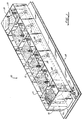
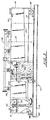
- Apparatus 10 is generally described as an oil/water separator vessel 10 sub-divided into a plurality of individual flotation cells 12. Separator vessel 10 is sealed and includes sidewalls 14, end walls 16, bottom support 18, and top cover 20 (in an alternate embodiment, vessel 10 may be cylindrical). Within separator vessel 10 are a series of divider walls 22 that separate vessel 10 into the several individual and generally identical cells 12. Discharge channel 24 is secured along one sidewall 14 with this channel 24 being sloped for gravity flow. Alongside other sidewall 14 are motors 26, pumps 28 and other plumbing equipment necessary for operation.
- SPIRALSEP 34 operates much the same as a stationary screw conveyer or auger in that it includes a central shaft 36 having a spiral blade 38 fixedly secured thereto. The shaft 36 and blades 38 do not rotate. As contaminated liquid is forced into inlet piping 32 it is forced to spin about the central axis defined by shaft 36 thus separating the oil and vapor from the contaminated water owing to the different densities and centrifugal force created.
- the oil and vapor are driven toward the center of curvature or axis of rotation.
- the solids and the liquids that constitute fluid 30 are physically forced along inlet piping 32 so as to prevent sludge from collecting and/or settling within this piping.
- this movement along piping 32 breaks up any large solids into smaller particles for better separation within vessel 10.
- This rotation also separates the contaminants from fluid 30 by centrifugal force.
- SPIRALSEP 34 utilizes entrained gas bubbles to scrub this incoming fluid 30, thereby creating an immediate frothing action within both piping 32 and first cell 12A. This initial frothing action permits the separation process within cell 12A to be more efficient, thereby reducing the load on the remaining cells 12B through 12F.
- fluid 30 is directed above the normal fluid level via inlet piping 32 before it is discharged into first cell 12A through orifice 40.
- Orifice 40 is configured with cap or umbrella 42 which evenly spreads fluid 30 throughout cell 12A while still retaining the froth and/or foam resulting from SPIRALSEP 34.
- the tiny gas bubbles 44 introduced by SPIRALSEP 34 attach to the solid and/or oil particles within fluid 30 causing them to rise to the surface.
- the foam then travels along the fluid surface towards weir 46 in sidewall 14. Afterwards, should the level of fluid 30 be high enough, this foam is discharged into channel 24 through weir 46.
- the height of weir 46 is adjustable as needed.
- L-shaped baffle 48 The fluid 30 remaining within first cell 12A travels near the bottom of this cell towards divider wall 22 where it passes through L-shaped baffle 48 into the next adjacent cell 12B (FIGURES 2, 3 and 5).
- Inlet opening 50 of L-shaped baffle 48 is located slightly above the bottom of cell 12A so as to prevent the entrance of heavy solids that have sunk to the bottom of this cell.
- L-shaped baffle 48 is configured having its exit opening 52 at an elevation above its inlet opening 50 so as to also prevent the movement of heavy solids from one cell to the next.
- L-shaped baffle 48 is angled such that exit 52 is located near the sidewall 14 opposite from weir 46 while inlet 50 is generally positioned nearer the sidewall 14 containing weir 46, and, in this embodiment, inlet 50 is located generally underneath weir 46.
- the entrance into each cell 12 is located diagonally opposite (in three dimensions) from the exit from this cell 12, thereby providing a fluid path along the longest possible distance within each cell 12 for maximum cleaning and/or separation.
- the upward discharge configuration of L-shaped baffle 48 aids in coalescing the oil droplets within fluid 30 because as the flow exits each L-shaped baffle 48, the oil is allowed to remain on the fluid surface due to micro-fine gas bubbles 44.
- FIGURE 6 best illustrates eductor or aeration assembly 54 which introduces micro-fine gas bubbles 44 into each of cells 12B, 12C, 12D and 12E (i.e., all but the first and last cells 12A and 12F) for separation purposes.
- Eductor assembly 54 operates in the typical fashion by withdrawing a slight amount of fluid 30 from the last cell 12F and then discharging this said withdrawn fluid, along with micro-fine gas bubbles 44, into earlier cells 12B through 12E.
- This eductor assembly 54 is of quick disconnect construction for ease of orifice removal and to permit rapid orifice changes to compensate for varying flow conditions.
- the orifice is located at the end of piping 56 which extends downward nearly to the tapered bottom of each cell 12 (FIGURE 6). This creates a flow pattern that directs the existing foam and any newly added solids toward weir 46.
- Pump 28 and motor 26 supply the necessary pressure to force these micro-fine bubbles 44 through piping 56.
- micro-fine bubbles 44 attach themselves to any solids or oil occurring in fluid 30, thereby causing these contaminates to rise to the surface with this foam gradually floating towards weir 46 for discharge into channel 24.
- the fluid 30 remaining within each cell 12 slowly gravitates towards L-shaped baffle 48 so as to flow into the next adjacent cell for further cleaning.
- FIGURE 7 illustrates in greater detail the configuration of weir 46.
- weir 46 consists of plate 58 having a V-shaped notch 60 therein and a pair of oppositely spaced slide holes 62. Plate 58 is secured to sidewall 14 via bolts 64 which extend through slide holes 62 as shown. In this fashion, the height of V-shaped notch 60 can be adjusted as needed with respect to sidewall 14 and the level of fluid 30 within each cell 12.
- the portion of fluid 30 that flows over weir 46 is collected within channel 24 and transported elsewhere via sludge outlet 66 (channel 24 is sloped upwardly from first cell 12A to last cell 12F for gravity flow to outlet 66).
- the portion of fluid 30 that remains within separator vessel 10 eventually makes its way into last cell 12F where this now cleaned and separated fluid is discharged via outlet 68.
- Cover 20 positively seals separator vessel 10, thereby retaining fluid 30 within this vessel.
- gasket material is located in a channel on the underneath side of cover 20 to seal vessel 10 against a coaming on the vessel top.
- Oil/water separator vessel 10 can be made available in a variety of sizes from around 1,000 BPD (30 GPM) up to 200,000 BPD (6,000 GPM) or more. Additionally, vessel 10 can be reshaped to fit available space without sacrificing efficiency or performance.
Landscapes
- Engineering & Computer Science (AREA)
- Chemical & Material Sciences (AREA)
- Chemical Kinetics & Catalysis (AREA)
- Life Sciences & Earth Sciences (AREA)
- Biotechnology (AREA)
- Physics & Mathematics (AREA)
- Thermal Sciences (AREA)
- General Engineering & Computer Science (AREA)
- Physical Water Treatments (AREA)
- Cyclones (AREA)
Applications Claiming Priority (2)
| Application Number | Priority Date | Filing Date | Title |
|---|---|---|---|
| US07/589,471 US5158678A (en) | 1990-09-28 | 1990-09-28 | Water clarification method and apparatus |
| US589471 | 1990-09-28 |
Publications (1)
| Publication Number | Publication Date |
|---|---|
| EP0483524A1 true EP0483524A1 (de) | 1992-05-06 |
Family
ID=24358162
Family Applications (1)
| Application Number | Title | Priority Date | Filing Date |
|---|---|---|---|
| EP91116580A Withdrawn EP0483524A1 (de) | 1990-09-28 | 1991-09-27 | Verfahren und Vorrichtung für die Wasserreinigung |
Country Status (6)
| Country | Link |
|---|---|
| US (4) | US5158678A (de) |
| EP (1) | EP0483524A1 (de) |
| JP (1) | JPH04247283A (de) |
| BR (1) | BR9104143A (de) |
| MY (1) | MY107913A (de) |
| NO (1) | NO302017B1 (de) |
Cited By (3)
| Publication number | Priority date | Publication date | Assignee | Title |
|---|---|---|---|---|
| RU2521631C1 (ru) * | 2013-02-27 | 2014-07-10 | Федеральное автономное учреждение "25 Государственный научно-исследовательский институт химмотологии Министерства обороны Российской Федерации" | Установка для отделения от воды нефтепродуктов и мехпримесей |
| EP3038725A4 (de) * | 2013-08-26 | 2017-05-17 | Exterran Water Solutions ULC | Gasflotationstank |
| US10377641B2 (en) | 2013-08-26 | 2019-08-13 | Exterran Water Solutions Ulc | Gas flotation tank |
Families Citing this family (93)
| Publication number | Priority date | Publication date | Assignee | Title |
|---|---|---|---|---|
| US5492622A (en) * | 1990-09-28 | 1996-02-20 | Broussard; Paul C. | Water clarification apparatus |
| US5376266A (en) * | 1990-09-28 | 1994-12-27 | Broussard; Paul C. | Water clarification method and apparatus |
| US5158678A (en) * | 1990-09-28 | 1992-10-27 | Broussard Paul C Sr | Water clarification method and apparatus |
| JP2573899B2 (ja) * | 1992-05-14 | 1997-01-22 | 株式会社エフ・テックス | 河川、湖沼等の浄化装置および油水分離装置 |
| NL9200975A (nl) * | 1992-06-03 | 1994-01-03 | Pacques Bv | Reactor voor de biologische behandeling van water. |
| US5543043A (en) * | 1992-07-01 | 1996-08-06 | Chevron U.S.A. Inc. | Clarification of produced water in the oil and gas industry |
| US5374352A (en) * | 1993-04-02 | 1994-12-20 | Pattee; Harley J. | Universal recycled wash water system |
| US5643459A (en) * | 1995-04-26 | 1997-07-01 | Cominco Engineering Services Ltd. | Flotation method and apparatus |
| US5643443A (en) * | 1995-05-19 | 1997-07-01 | Taiki Corporation, U.S.A. | Water purification system |
| SE503569C2 (sv) * | 1995-07-06 | 1996-07-08 | Andreas Schelin | Anordning för avskiljning av olja ur vatten |
| US5639366A (en) * | 1995-09-01 | 1997-06-17 | Bazell Technologies Corporation | Concentrator for solids in a liquid medium |
| US6149805A (en) * | 1995-11-13 | 2000-11-21 | Ab Ribea Engineering | Device for adding oxygen to water |
| NL1002158C2 (nl) * | 1996-01-23 | 1997-07-25 | Int Business Dev Inc | Inrichting voor het scheiden van materialen, in het bijzonder voor het uit water afscheiden van olie en andere bestanddelen. |
| US5656173A (en) * | 1996-03-05 | 1997-08-12 | National Tank Company | Method of removing dispersed oil from an oil in water emulsion employing aerated solutions within a coalescing media |
| US6036871A (en) * | 1996-04-25 | 2000-03-14 | Fan Separator Gmbh | Method and device for separating heavier from lighter parts of aqueous slurries by means of centrifugal force effects |
| DE19732208C2 (de) * | 1997-07-26 | 2001-03-01 | Olt Oberflaechen Luft Und Troc | Wasserbetriebene Vorrichtung zum Aufnehmen und Absetzenlassen von Lackpartikeln |
| AUPO887597A0 (en) | 1997-08-29 | 1997-09-25 | Separation Technologies Group Pty Ltd | Mixing apparatus |
| AUPP101297A0 (en) * | 1997-12-18 | 1998-01-15 | Crocker, Stephen | Separators for oil, gas, mud and solids |
| US6074557A (en) * | 1998-02-02 | 2000-06-13 | Lyles, Sr.; Robert G. | Water treatment device and method |
| RU2146228C1 (ru) * | 1998-04-06 | 2000-03-10 | Пономарев Виктор Георгиевич | Импеллерный флотатор |
| US6328118B1 (en) * | 1999-03-08 | 2001-12-11 | Halliburton Energy Services, Inc. | Apparatus and methods of separation of materials in an under-balanced drilling operation |
| US6234258B1 (en) | 1999-03-08 | 2001-05-22 | Halliburton Energy Services, Inc. | Methods of separation of materials in an under-balanced drilling operation |
| DE19957570A1 (de) * | 1999-11-30 | 2001-05-31 | Linde Kca Dresden Gmbh | Lamellenklärer |
| AU2001229393A1 (en) * | 2000-01-13 | 2001-07-24 | Z.P.M., Inc. | System and method to improve flotation systems |
| US6645382B1 (en) | 2000-11-13 | 2003-11-11 | George E. Wilson | Energy-efficient head cell entry duct |
| EP1208897A1 (de) | 2000-11-21 | 2002-05-29 | Epcon Norge AS | Behälter zur kombinierten Entgasung und Flotation |
| US6869528B2 (en) * | 2001-02-26 | 2005-03-22 | Thomas E. Pank | Filtering system for runoff water |
| US6632352B2 (en) | 2001-07-11 | 2003-10-14 | Nursery Pro, Inc. | Multi-stage filter |
| KR100427594B1 (ko) * | 2001-09-18 | 2004-04-30 | 정인 | 미세기포를 이용하여 하폐수에서 용존성 고형물과 부유성고형물을 동시에 제거하는 폐수처리 장치 및 방법 |
| FI115447B (fi) * | 2002-03-18 | 2005-05-13 | Outokumpu Oy | Vaahdotuslaitteisto ja -menetelmä |
| US7157007B2 (en) * | 2003-06-20 | 2007-01-02 | National Tank Company | Vertical gas induced flotation cell |
| GB2403440B (en) * | 2003-07-04 | 2007-09-05 | Dynamic Proc Solutions Plc | Separator |
| US7507333B2 (en) * | 2003-10-25 | 2009-03-24 | Thomas E. Pank | Method of and apparatus for cleaning runoff water |
| NO321082B1 (no) * | 2003-12-11 | 2006-03-13 | Consept As | Flotasjonsseparator |
| US20060001260A1 (en) * | 2004-06-30 | 2006-01-05 | Thompson David M | Fluid vortex manifold |
| US7735186B1 (en) * | 2004-12-10 | 2010-06-15 | Vogel Hans E | Surface cleaning vehicle |
| GB2423490B (en) * | 2005-02-23 | 2009-05-20 | Dps | Separator |
| FR2883279B1 (fr) * | 2005-03-16 | 2007-06-08 | Bernard Beaulieu | Installation de purification d'effluent a structure centralisee |
| EP1881946B1 (de) * | 2005-05-19 | 2012-11-21 | M-I L.L.C. | Trennungs- und behandlungssystem für ölbasierten schlamm |
| US20070051675A1 (en) * | 2005-06-14 | 2007-03-08 | Paul Lindh | Filter device and method for filtering |
| US20060283788A1 (en) * | 2005-06-21 | 2006-12-21 | Schreppel Rudy Jr | Tri-clone system |
| US20060283805A1 (en) * | 2005-06-21 | 2006-12-21 | Schreppel Rudy Jr | Advanced separator system |
| WO2007022450A1 (en) * | 2005-08-18 | 2007-02-22 | Clean Filtration Technologies, Inc. | Hydroclone based fluid filtration system |
| EP1782869A1 (de) * | 2005-10-28 | 2007-05-09 | M-I Epcon As | Schwerkraft-Abscheider. |
| US8080158B2 (en) | 2005-11-22 | 2011-12-20 | Exterran Water Solutions Ulc | Vessel and method for treating contaminated water |
| CA2527543C (en) * | 2005-11-22 | 2011-11-08 | Glr Solutions Ltd. | Vessel and method for treating contaminated water |
| FR2896433B1 (fr) * | 2006-01-20 | 2008-04-18 | Bernard Beaulieu | Installation domestique de purification d'effluents |
| DE102006017635A1 (de) * | 2006-04-12 | 2007-10-18 | Mann + Hummel Gmbh | Mehrstufige Vorrichtung zum Abscheiden von Flüssigkeitstropfen aus Gasen |
| CA2551684A1 (en) * | 2006-07-10 | 2008-01-10 | Hollman, Don | Improved flock tank |
| US9193613B2 (en) | 2006-10-03 | 2015-11-24 | Siemens Energy, Inc. | pH control to enable homogeneous catalytic wet air oxidation |
| US7491336B2 (en) | 2006-11-01 | 2009-02-17 | Rimkus Consulting Group, Inc. | Process for treating industrial effluent water with activated media |
| US9315401B2 (en) | 2007-01-22 | 2016-04-19 | Siemens Energy, Inc. | Wet air oxidation process using recycled copper catalyst |
| US8715512B2 (en) * | 2007-04-03 | 2014-05-06 | Siemens Energy, Inc. | Systems and methods for liquid separation |
| DE202007008129U1 (de) * | 2007-06-06 | 2008-10-16 | Gkd - Gebr. Kufferath Ag | Vorrichtung zum Pflegen, Filtrieren und/oder Reinigen eines Mediums |
| US8101071B2 (en) * | 2007-06-29 | 2012-01-24 | Caterpillar Inc. | Oil removal reclamation clarifier system and process for use |
| GB2453737A (en) * | 2007-10-16 | 2009-04-22 | Peter Stanton Edwards | Separation apparatus |
| TWI467087B (zh) * | 2008-03-25 | 2015-01-01 | Amicable Inv S Llc | 與空氣或氣體交互作用的設備及其噴射發動機 |
| GB0806172D0 (en) * | 2008-04-04 | 2008-05-14 | Vws Westgarth Ltd | Fluid treatment system |
| MX2011005818A (es) | 2008-12-01 | 2011-09-06 | Veolia Water Solutions & Tech | Metodo y aparato para la extraccion de lodo procedente de aguas residuales. |
| CN102333577B (zh) | 2009-02-26 | 2014-04-09 | Fl史密斯公司 | 横进给转动式增稠器/澄清器供料口组件 |
| US8114296B2 (en) * | 2009-04-23 | 2012-02-14 | Fang Chao | Method and apparatus for skimming floated sludge |
| US8303812B2 (en) | 2009-04-23 | 2012-11-06 | Fang Chao | Method and apparatus for skimming floated sludge |
| CA2798425C (en) | 2009-05-06 | 2018-03-20 | Triverus, Llc | Surface cleaning and recycling apparatus and method |
| US8708065B2 (en) * | 2009-06-03 | 2014-04-29 | National Oilwell Varco, L.P. | Vessel to condition dry drill cuttings |
| CN101559407B (zh) * | 2009-06-08 | 2013-05-29 | 金易通科技(北京)股份有限公司 | 一种模块式组合浮选机及其模块化槽体 |
| JP4621802B1 (ja) * | 2010-02-09 | 2011-01-26 | 株式会社ワールドケミカル | 自吸式固液分離装置 |
| US8882999B2 (en) | 2010-06-17 | 2014-11-11 | Dow Global Technologies Llc | Cleaning assembly for use in fluid filtration systems |
| US8960450B2 (en) | 2010-12-08 | 2015-02-24 | Dow Global Technologies Llc | Apparatus and method for implementing hydroclone based fluid filtration systems with extensible isolated filter stages |
| SE535787C2 (sv) * | 2010-12-22 | 2012-12-18 | Ninni Petersson | Vattenrenare och metod för att rena vatten |
| PH12013501914A1 (en) | 2011-02-18 | 2013-10-14 | Nexen Energy Ulc | H2s conversion to sulfur using a regenerated iodine solution |
| US9095786B1 (en) * | 2011-03-04 | 2015-08-04 | Enviro-Tech Systems, L.L.C. | Method and apparatus for separation of fluids within a single vessel |
| US8834724B1 (en) * | 2011-03-16 | 2014-09-16 | Enviro-Tech Systems, L.L.C. | Method and apparatus for separation of fluids by means of induced gas flotation and advances in said technology |
| EP2646129B1 (de) | 2011-05-06 | 2015-07-15 | Dow Global Technologies LLC | Mehrkammer-hydrozyklon |
| US20130075338A1 (en) * | 2011-09-22 | 2013-03-28 | Terry C. Murtagh | Induced-Gas Flotation Cell with Horizontal Flow |
| JP5905239B2 (ja) * | 2011-10-28 | 2016-04-20 | 有限会社山口ティー・エル・オー | 油水分離装置とそれを備えた廃水処理システム |
| US9050610B2 (en) | 2012-05-17 | 2015-06-09 | Dow Global Technologies Llc | Hydroclone with inlet flow shield |
| US9186604B1 (en) | 2012-05-31 | 2015-11-17 | Dow Global Technologies Llc | Hydroclone with vortex flow barrier |
| US9101859B2 (en) | 2012-06-01 | 2015-08-11 | Dow Global Technologies Llc | Cross-flow filtration system including particulate settling zone |
| DE102012107471A1 (de) * | 2012-08-15 | 2014-05-22 | Ava-Co2 Schweiz Ag | Verfahren und Vorrichtung zur Reinigung von Prozesswasser in einem hydrothermalen Karbonisierungsprozess |
| WO2014066036A2 (en) | 2012-10-26 | 2014-05-01 | Dow Global Technologies Llc | Hydroclone |
| US10301196B2 (en) | 2013-06-15 | 2019-05-28 | Exactration, Llc | Skimmer and oil water separator |
| CN105960286B (zh) | 2013-12-05 | 2019-01-29 | 陶氏环球技术有限责任公司 | 具有改进的清洁组合件的水力旋流器 |
| US10611649B2 (en) | 2016-12-06 | 2020-04-07 | Exactration, Llc | Skimmer and oil water separator process |
| CA2971175C (en) | 2014-12-18 | 2024-01-23 | Dow Global Technologies Llc | Cylindrical filter screen with tensioning mechanism |
| US9889391B2 (en) * | 2015-03-25 | 2018-02-13 | Veolia Water Solutions & Technologies Support | Degasser and method of stripping gas from a liquid |
| KR101666603B1 (ko) * | 2015-04-09 | 2016-10-14 | 태경중공업주식회사 | 열효율이 높은 3상 세퍼레이터 |
| US10967316B2 (en) | 2017-07-20 | 2021-04-06 | The University Of Tulsa | Compact gas-liquid filtration cyclone separation unit |
| US11247145B2 (en) | 2017-12-13 | 2022-02-15 | The University Of Tulsa | Gas—liquid flow splitting (GLFS) system |
| WO2020151080A1 (zh) * | 2019-01-22 | 2020-07-30 | 无锡洋湃科技有限公司 | 自励式湿气流量测量装置 |
| US11008227B2 (en) | 2019-07-29 | 2021-05-18 | Eco Water Technologies Corp | Wastewater purification system |
| CN110433531A (zh) * | 2019-09-06 | 2019-11-12 | 河海大学 | 一种餐饮废水油水分离器 |
| CN111686950B (zh) * | 2020-06-11 | 2022-01-07 | 中科合成油技术股份有限公司 | 一种高温高压下油水快速分离的方法及装置 |
| CA3090353C (en) | 2020-08-18 | 2026-01-06 | 1501367 Alberta Ltd. | Fluid treatment separator and a system and method of treating fluid |
Citations (3)
| Publication number | Priority date | Publication date | Assignee | Title |
|---|---|---|---|---|
| US2730190A (en) * | 1952-02-08 | 1956-01-10 | Union Oil Co | Treatment of oil-containing water |
| US4226706A (en) * | 1979-08-09 | 1980-10-07 | Envirotech Corporation | Dispersed air flotation machine |
| US4824579A (en) * | 1987-04-20 | 1989-04-25 | George Albert L | Water clarification method and apparatus |
Family Cites Families (84)
| Publication number | Priority date | Publication date | Assignee | Title |
|---|---|---|---|---|
| US1166802A (en) * | 1915-04-21 | 1916-01-04 | Jacob P Albert | Filtering apparatus. |
| US1346817A (en) * | 1915-06-26 | 1920-07-20 | Pneumatic Process Flotation Co | Flotation ore-separator and process |
| US1457077A (en) * | 1919-08-21 | 1923-05-29 | Thomas A Janney | Flotation machine |
| US1542666A (en) * | 1923-11-27 | 1925-06-16 | Continuous Clarifier And Settl | Continuous clarifying apparatus |
| US1807823A (en) * | 1926-11-24 | 1931-06-02 | Gen Engineering Co | Flotation |
| US1886979A (en) * | 1931-01-26 | 1932-11-08 | Jr Joseph P Ruth | Flotation method |
| US1951647A (en) * | 1931-06-06 | 1934-03-20 | Standard Oil Co | Sludge separator |
| US2184115A (en) * | 1938-09-27 | 1939-12-19 | Hugh W Coke | Apparatus for flotation concentration of ores |
| US2316770A (en) * | 1940-05-27 | 1943-04-20 | Mining Process & Patent Co | Froth flotation apparatus and treatment |
| US2612358A (en) * | 1947-06-14 | 1952-09-30 | Mining Process & Patent Co | Pumping-type flotation apparatus |
| US2765918A (en) * | 1953-05-11 | 1956-10-09 | Stamicarbon | Multiple hydrocyclone |
| US2994432A (en) * | 1957-06-03 | 1961-08-01 | Pfaudler Permutit Inc | Control for flotation separation systems |
| SU119117A1 (ru) * | 1958-01-04 | 1958-11-30 | Б.В. Иванов | Способ изготовлени огнеупора на основе окиси кальци с пониженной температурой начала уплотнени |
| US3010805A (en) * | 1959-09-24 | 1961-11-28 | Gen Am Transport | Classifying crystallizers and systems |
| US3045828A (en) * | 1959-11-16 | 1962-07-24 | George W Hume | Sand extractor |
| US2967618A (en) * | 1960-03-28 | 1961-01-10 | Vane Zdenek | Vortical separator |
| US3477581A (en) * | 1967-09-21 | 1969-11-11 | Donald M Stearns | Sewage disposal system |
| US3708067A (en) * | 1970-06-29 | 1973-01-02 | Battelle Development Corp | Separating apparatus |
| DE2063892A1 (de) * | 1970-12-24 | 1972-07-06 | Siemens Ag | Vorrichtung zum Abscheiden von Feststoffen aus Flüssigkeiten |
| US3717255A (en) * | 1971-04-28 | 1973-02-20 | Bauer Bros Co | Liquid clarification unit |
| US3698558A (en) * | 1971-04-29 | 1972-10-17 | Roland E Weber | Anti-pollution device for removing debris from liquid |
| US3723309A (en) * | 1971-09-20 | 1973-03-27 | Exxon Production Research Co | System and method for cleaning oily solid material |
| US3960734A (en) * | 1972-10-10 | 1976-06-01 | Antoni Zagorski | High efficiency cyclone separator |
| US3959139A (en) * | 1974-09-16 | 1976-05-25 | Filter Tech, Inc. | Liquid purification system |
| US3972815A (en) * | 1975-01-09 | 1976-08-03 | United States Filter Corporation | Mixing apparatus |
| US4031006A (en) * | 1976-03-12 | 1977-06-21 | Swift And Company Limited | Vortex coagulation means and method for wastewater clarification |
| US4049553A (en) * | 1976-04-12 | 1977-09-20 | Stebbins George B | Water polishing means for removing oil and other flotsam from water |
| US4274968A (en) * | 1977-06-15 | 1981-06-23 | Standard Oil Company (Indiana) | Process for the purification of water |
| US4316729A (en) * | 1977-12-27 | 1982-02-23 | Texaco Inc. | Highly efficient cyclone separator |
| US4208270A (en) * | 1978-03-27 | 1980-06-17 | Krebs Engineers | Hydrocyclone assembly |
| US4216085A (en) * | 1978-08-18 | 1980-08-05 | Iowa Beef Processors, Inc. | Flotation method and apparatus |
| US4255262A (en) * | 1979-03-26 | 1981-03-10 | U.S. Filter Corporation | Hydraulic powered mixing apparatus |
| US4220612A (en) * | 1979-04-23 | 1980-09-02 | Envirotech Corporation | Flotation cell feed duct |
| EP0024148B1 (de) * | 1979-08-09 | 1985-02-13 | The British Petroleum Company p.l.c. | Abscheider für Öl, Gas und Wasser |
| SU996333A1 (ru) * | 1981-07-03 | 1983-02-15 | Московский Ордена Трудового Красного Знамени Инженерно-Строительный Институт Им.В.В.Куйбышева | Способ флотационной очистки воды |
| SU1143437A1 (ru) * | 1983-06-13 | 1985-03-07 | Тюменский инженерно-строительный институт | Устройство дл очистки сточных вод |
| JPS6028880A (ja) * | 1983-07-28 | 1985-02-14 | Mizu Kemikaruzu:Kk | 排水の油分離装置 |
| JPS6038007A (ja) * | 1983-08-11 | 1985-02-27 | Yks Co Ltd | 船舶用油水分離装置 |
| US4673495A (en) * | 1983-08-11 | 1987-06-16 | Noel Carroll | Enclosed cyclone separators |
| SU1121236A1 (ru) * | 1983-08-18 | 1984-10-30 | Предприятие П/Я М-5828 | Устройство дл осветлени нефтесодержащих сточных вод |
| US4564457A (en) * | 1983-11-03 | 1986-01-14 | L'eau Claire Systems, Inc. | Upflow gas eductor induced air floatation separator |
| DE3410143A1 (de) * | 1984-03-20 | 1985-10-03 | Deutsche Babcock Werke AG, 4200 Oberhausen | Vorrichtung zum entstauben von unter druck stehendem gas |
| US4626345A (en) * | 1984-09-04 | 1986-12-02 | Lenox Institute For Research, Inc. | Apparatus for clarification of water |
| SU1228913A1 (ru) * | 1984-11-23 | 1986-05-07 | Казанский инженерно-строительный институт | Устройство дл очистки сточных вод |
| MX167588B (es) * | 1984-11-28 | 1993-03-31 | Conoco Specialty Prod | Aparato para procesar petroleo |
| FI71175C (fi) * | 1985-01-16 | 1990-10-14 | Suomen Puhallintehdas Oy | Arrangemang foer matande av kantband e.d. i en pulper. |
| US4824563A (en) * | 1985-12-04 | 1989-04-25 | Kabushiki Kaisha Meidensha | Equipment for treating waste water |
| SU1322216A1 (ru) * | 1985-12-16 | 1987-07-07 | Харьковский политехнический институт им.В.И.Ленина | Флотационный аппарат дл реагентной очистки сточных вод |
| SU1306604A1 (ru) * | 1985-12-30 | 1987-04-30 | Всесоюзный Научно-Исследовательский И Проектно-Изыскательский Институт По Проблемам Добычи,Транспорта И Переработки Минерального Сырья В Промышленности Строительных Материалов | Комбинированный гидроциклон |
| DE3639958A1 (de) * | 1986-01-10 | 1987-07-16 | Amberger Kaolinwerke Gmbh | Mehrstufige anordnung zur gegenstromwaschung, sowie zugehoerige verfahrensmassnahmen |
| US4738784A (en) * | 1986-07-03 | 1988-04-19 | Kazutoyo Sugihara | Flotation device |
| US4800025A (en) * | 1986-08-20 | 1989-01-24 | Pony Industries, Inc. | Apparatus and process for the gas flotation purification of oil-contaminated water |
| FR2605898B1 (fr) * | 1986-11-04 | 1990-04-27 | Elf Aquitaine | Separateur pour deux liquides non miscibles |
| US5100546A (en) * | 1986-12-05 | 1992-03-31 | Broussard Paul C Sr | Liquid-to-liquid oil absorption system and method |
| US4728428A (en) * | 1986-12-05 | 1988-03-01 | Paul C. Broussard, Inc. | Water degreasing system and method |
| SU1421709A1 (ru) * | 1987-01-04 | 1988-09-07 | Уральский Научно-Исследовательский Институт Комплексного Использования И Охраны Водных Ресурсов | Устройство дл очистки воды от масел |
| SU1416443A1 (ru) * | 1987-01-26 | 1988-08-15 | Всесоюзный Научно-Исследовательский Институт Железнодорожного Транспорта | Устройство дл очистки нефтесодержащих сточных вод |
| US4726902A (en) * | 1987-05-01 | 1988-02-23 | Dorr-Oliver Incorporated | Cyclone degritter for solids liquids separation |
| US5021165A (en) * | 1987-06-10 | 1991-06-04 | Conoco Specialty Products | Oil and water separating system with hydrocyclone and floatation device |
| SU1526836A1 (ru) * | 1987-07-13 | 1989-12-07 | Киевский Технологический Институт Пищевой Промышленности | Гидроциклон дл отделени газа от жидкости |
| SU1535578A1 (ru) * | 1987-07-22 | 1990-01-15 | Свердловский горный институт им.В.В.Вахрушева | Устройство дл обезвоживани суспензий |
| JPH01104315A (ja) * | 1987-07-30 | 1989-04-21 | Mitsubishi Oil Co Ltd | 原動機または油圧機器における潤滑油中の固体および気体異物の一体型分離除去装置 |
| US4783272A (en) * | 1987-08-28 | 1988-11-08 | Atlantic Richfield Company | Removing solids from process separator vessels |
| SU1480847A1 (ru) * | 1987-09-09 | 1989-05-23 | Государственный институт по проектированию и исследовательским работам в нефтяной промышленности "Гипровостокнефть" | Аппарат дл совместной подготовки нефти и воды |
| US4782789A (en) * | 1987-10-26 | 1988-11-08 | Eau Claire Systems Inc | Induced static flotation cell |
| SU1563767A1 (ru) * | 1987-11-02 | 1990-05-15 | Кубанский сельскохозяйственный институт | Газожидкостный сепаратор |
| GB8804922D0 (en) * | 1988-03-02 | 1988-03-30 | Hill Venning J | Interceptor |
| US4986903A (en) * | 1988-10-11 | 1991-01-22 | Canzoneri Anthony S | Induced static single flotation cell |
| JPH02112321A (ja) * | 1988-10-21 | 1990-04-25 | Nec Corp | 符号変換方式 |
| SU1687577A1 (ru) * | 1989-01-12 | 1991-10-30 | Инженерный центр "Трубопровод" | Устройство дл очистки парогазонефтесодержащих вод Чесалова и Шишкина |
| SU1636006A1 (ru) * | 1989-04-14 | 1991-03-23 | Предприятие П/Я М-5478 | Установка дл предварительного обезвоживани высокообводненной нефти с очисткой пластовой воды |
| SU1699941A1 (ru) * | 1989-12-25 | 1991-12-23 | Предприятие П/Я М-5478 | Устройство дл очистки нефтесодержащих сточных вод |
| US5080802A (en) * | 1990-05-09 | 1992-01-14 | Cairo Jr John A | Induced gas liquid coalescer and flotation separator |
| US5069783A (en) * | 1990-05-16 | 1991-12-03 | Int'l Environmental Systems, Inc. | Liquid treatment apparatus |
| US5112479A (en) * | 1990-05-30 | 1992-05-12 | Micropure Filtration, Inc. | Oil purification unit with cyclonic reservoir section and filtration section |
| US5049320A (en) * | 1990-07-03 | 1991-09-17 | International Environmental Systems, Inc. | Gas dissolving system and method |
| US5068031A (en) * | 1990-07-06 | 1991-11-26 | Int'l Environmental Systems, Inc. | Sludge treatment apparatus |
| US5084165A (en) * | 1990-07-06 | 1992-01-28 | Int'l Environmental Systems, Inc. | Water treatment apparatus |
| US5064531A (en) * | 1990-07-26 | 1991-11-12 | Int'l Environmental Systems, Inc. | Water filtration apparatus |
| US5084189A (en) * | 1990-09-21 | 1992-01-28 | Richter Systems, Inc. | Method and apparatus for separating fluids having different specific gravities |
| US5158678A (en) * | 1990-09-28 | 1992-10-27 | Broussard Paul C Sr | Water clarification method and apparatus |
| US5173184A (en) * | 1990-11-21 | 1992-12-22 | Hydro Modular System, Inc. | Wastewater treatment apparatus |
| US5209765A (en) * | 1991-05-08 | 1993-05-11 | Atlantic Richfield Company | Centrifugal separator systems for multi-phase fluids |
| US5202026A (en) * | 1992-04-03 | 1993-04-13 | The United States Of America As Represented By The Secretary Of The Navy | Combined centrifugal force/gravity gas/liquid separator system |
-
1990
- 1990-09-28 US US07/589,471 patent/US5158678A/en not_active Expired - Lifetime
-
1991
- 1991-09-24 MY MYPI91001726A patent/MY107913A/en unknown
- 1991-09-26 BR BR919104143A patent/BR9104143A/pt not_active IP Right Cessation
- 1991-09-27 JP JP3249667A patent/JPH04247283A/ja active Pending
- 1991-09-27 EP EP91116580A patent/EP0483524A1/de not_active Withdrawn
- 1991-09-27 NO NO913807A patent/NO302017B1/no unknown
-
1992
- 1992-10-23 US US07/965,888 patent/US5277803A/en not_active Expired - Fee Related
-
1993
- 1993-03-08 US US08/026,877 patent/US5300222A/en not_active Expired - Fee Related
- 1993-09-20 US US08/123,231 patent/US5407584A/en not_active Expired - Lifetime
Patent Citations (3)
| Publication number | Priority date | Publication date | Assignee | Title |
|---|---|---|---|---|
| US2730190A (en) * | 1952-02-08 | 1956-01-10 | Union Oil Co | Treatment of oil-containing water |
| US4226706A (en) * | 1979-08-09 | 1980-10-07 | Envirotech Corporation | Dispersed air flotation machine |
| US4824579A (en) * | 1987-04-20 | 1989-04-25 | George Albert L | Water clarification method and apparatus |
Cited By (4)
| Publication number | Priority date | Publication date | Assignee | Title |
|---|---|---|---|---|
| RU2521631C1 (ru) * | 2013-02-27 | 2014-07-10 | Федеральное автономное учреждение "25 Государственный научно-исследовательский институт химмотологии Министерства обороны Российской Федерации" | Установка для отделения от воды нефтепродуктов и мехпримесей |
| EP3038725A4 (de) * | 2013-08-26 | 2017-05-17 | Exterran Water Solutions ULC | Gasflotationstank |
| US9890059B2 (en) | 2013-08-26 | 2018-02-13 | Exterran Water Solutions Ulc | Gas flotation tank |
| US10377641B2 (en) | 2013-08-26 | 2019-08-13 | Exterran Water Solutions Ulc | Gas flotation tank |
Also Published As
| Publication number | Publication date |
|---|---|
| BR9104143A (pt) | 1992-06-02 |
| US5277803A (en) | 1994-01-11 |
| US5300222A (en) | 1994-04-05 |
| NO913807L (no) | 1992-03-30 |
| MY107913A (en) | 1996-06-29 |
| NO302017B1 (no) | 1998-01-12 |
| JPH04247283A (ja) | 1992-09-03 |
| NO913807D0 (no) | 1991-09-27 |
| US5407584A (en) | 1995-04-18 |
| US5158678A (en) | 1992-10-27 |
Similar Documents
| Publication | Publication Date | Title |
|---|---|---|
| US5158678A (en) | Water clarification method and apparatus | |
| US5522999A (en) | Water clarification method | |
| US5382358A (en) | Apparatus for dissolved air floatation and similar gas-liquid contacting operations | |
| US5376266A (en) | Water clarification method and apparatus | |
| US3794171A (en) | Apparatus for purifying waste liquids | |
| KR100919367B1 (ko) | 고효율 기체용해탱크를 이용한 부상분리장치 | |
| US3647069A (en) | Enclosed flotation apparatus and process | |
| US4362620A (en) | Partitioned centrifuge | |
| US4341630A (en) | Arrangement for separation of a suspension or emulsion from liquids by flotation | |
| US4746440A (en) | Process and apparatus for the separation of emulsions or of solids from a suspension of solids and a liquid by means of pressure or turbo flotation | |
| US20140190897A1 (en) | Enhanced separation of nuisance materials from wastewater | |
| KR100298064B1 (ko) | 용존공기부상식 수처리장치 | |
| US5681458A (en) | Water clarification employing rotating drum skimmer | |
| US5160610A (en) | Radial header for dissolved air flotation systems | |
| US8173017B2 (en) | Single-cell mechanical flotation system | |
| US6719911B2 (en) | Apparatus and method for the treatment of a contaminated fluid | |
| EP0826404B1 (de) | Behälter zum Entgasen von Wasser | |
| EP0695719A1 (de) | Verfahren und Vorrichtung zur Flotation mit gelöster Luft und ähnliche Gas-Flüssigkeits-Kontaktverfahren | |
| FI79792B (fi) | Flotationsanordning och -foerfarande. | |
| CN118993458B (zh) | 一种用于石油化工炼油的油水深度分离装置及工艺 | |
| US4882068A (en) | Method and apparatus for removing liquid from suspensions | |
| RU2052386C1 (ru) | Способ и установка для очистки сточных вод от взвешенных волокнистых загрязнений | |
| JP2892604B2 (ja) | 溶解空気浮選および同様な気液接触操作の為の方法と装置 | |
| EP1600425B1 (de) | Vorrichtung zur abwasserbehandlung | |
| SU1340793A1 (ru) | Устройство дл очистки жидкостей |
Legal Events
| Date | Code | Title | Description |
|---|---|---|---|
| PUAI | Public reference made under article 153(3) epc to a published international application that has entered the european phase |
Free format text: ORIGINAL CODE: 0009012 |
|
| AK | Designated contracting states |
Kind code of ref document: A1 Designated state(s): AT BE CH DE DK ES FR GB GR IT LI LU NL SE |
|
| 17P | Request for examination filed |
Effective date: 19921104 |
|
| 17Q | First examination report despatched |
Effective date: 19930617 |
|
| STAA | Information on the status of an ep patent application or granted ep patent |
Free format text: STATUS: THE APPLICATION IS DEEMED TO BE WITHDRAWN |
|
| 18D | Application deemed to be withdrawn |
Effective date: 19931028 |