EP0483528B1 - Système de vitres isolantes - Google Patents
Système de vitres isolantes Download PDFInfo
- Publication number
- EP0483528B1 EP0483528B1 EP91116631A EP91116631A EP0483528B1 EP 0483528 B1 EP0483528 B1 EP 0483528B1 EP 91116631 A EP91116631 A EP 91116631A EP 91116631 A EP91116631 A EP 91116631A EP 0483528 B1 EP0483528 B1 EP 0483528B1
- Authority
- EP
- European Patent Office
- Prior art keywords
- insulating glass
- foil
- glass arrangement
- counterpull
- sunshade
- Prior art date
- Legal status (The legal status is an assumption and is not a legal conclusion. Google has not performed a legal analysis and makes no representation as to the accuracy of the status listed.)
- Expired - Lifetime
Links
- 239000011521 glass Substances 0.000 title claims abstract description 43
- 238000010276 construction Methods 0.000 title abstract description 6
- 238000009413 insulation Methods 0.000 title abstract description 5
- 239000011888 foil Substances 0.000 claims abstract description 22
- 125000006850 spacer group Chemical group 0.000 claims abstract description 13
- 229910052782 aluminium Inorganic materials 0.000 claims description 8
- XAGFODPZIPBFFR-UHFFFAOYSA-N aluminium Chemical compound [Al] XAGFODPZIPBFFR-UHFFFAOYSA-N 0.000 claims description 8
- 229910052751 metal Inorganic materials 0.000 claims description 8
- 239000002184 metal Substances 0.000 claims description 8
- 238000004804 winding Methods 0.000 claims description 6
- RYGMFSIKBFXOCR-UHFFFAOYSA-N Copper Chemical compound [Cu] RYGMFSIKBFXOCR-UHFFFAOYSA-N 0.000 claims description 4
- 229920003023 plastic Polymers 0.000 claims description 4
- 239000004033 plastic Substances 0.000 claims description 4
- 229920000728 polyester Polymers 0.000 claims description 2
- 239000005030 aluminium foil Substances 0.000 claims 1
- 239000011889 copper foil Substances 0.000 claims 1
- 230000037072 sun protection Effects 0.000 description 25
- 238000009434 installation Methods 0.000 description 6
- 229910052802 copper Inorganic materials 0.000 description 3
- 239000010949 copper Substances 0.000 description 3
- 238000003475 lamination Methods 0.000 description 3
- 239000000463 material Substances 0.000 description 3
- 230000009993 protective function Effects 0.000 description 3
- 229910000639 Spring steel Inorganic materials 0.000 description 2
- 230000005540 biological transmission Effects 0.000 description 2
- 238000000576 coating method Methods 0.000 description 2
- 230000008878 coupling Effects 0.000 description 2
- 238000010168 coupling process Methods 0.000 description 2
- 238000005859 coupling reaction Methods 0.000 description 2
- 230000007774 longterm Effects 0.000 description 2
- 238000009877 rendering Methods 0.000 description 2
- 238000010521 absorption reaction Methods 0.000 description 1
- 238000004026 adhesive bonding Methods 0.000 description 1
- 238000004378 air conditioning Methods 0.000 description 1
- 239000011248 coating agent Substances 0.000 description 1
- 230000007797 corrosion Effects 0.000 description 1
- 238000005260 corrosion Methods 0.000 description 1
- 230000007423 decrease Effects 0.000 description 1
- 238000011161 development Methods 0.000 description 1
- 230000018109 developmental process Effects 0.000 description 1
- 230000000694 effects Effects 0.000 description 1
- 230000007613 environmental effect Effects 0.000 description 1
- 230000004313 glare Effects 0.000 description 1
- PCHJSUWPFVWCPO-UHFFFAOYSA-N gold Chemical compound [Au] PCHJSUWPFVWCPO-UHFFFAOYSA-N 0.000 description 1
- 229910052737 gold Inorganic materials 0.000 description 1
- 239000010931 gold Substances 0.000 description 1
- 230000010354 integration Effects 0.000 description 1
- 150000002739 metals Chemical class 0.000 description 1
- 230000007935 neutral effect Effects 0.000 description 1
- 210000002445 nipple Anatomy 0.000 description 1
- 230000005855 radiation Effects 0.000 description 1
- 238000007789 sealing Methods 0.000 description 1
- 229910052709 silver Inorganic materials 0.000 description 1
- 239000004332 silver Substances 0.000 description 1
Images



Classifications
-
- E—FIXED CONSTRUCTIONS
- E06—DOORS, WINDOWS, SHUTTERS, OR ROLLER BLINDS IN GENERAL; LADDERS
- E06B—FIXED OR MOVABLE CLOSURES FOR OPENINGS IN BUILDINGS, VEHICLES, FENCES OR LIKE ENCLOSURES IN GENERAL, e.g. DOORS, WINDOWS, BLINDS, GATES
- E06B9/00—Screening or protective devices for wall or similar openings, with or without operating or securing mechanisms; Closures of similar construction
- E06B9/24—Screens or other constructions affording protection against light, especially against sunshine; Similar screens for privacy or appearance; Slat blinds
- E06B9/26—Lamellar or like blinds, e.g. venetian blinds
- E06B9/264—Combinations of lamellar blinds with roller shutters, screen windows, windows, or double panes; Lamellar blinds with special devices
-
- E—FIXED CONSTRUCTIONS
- E06—DOORS, WINDOWS, SHUTTERS, OR ROLLER BLINDS IN GENERAL; LADDERS
- E06B—FIXED OR MOVABLE CLOSURES FOR OPENINGS IN BUILDINGS, VEHICLES, FENCES OR LIKE ENCLOSURES IN GENERAL, e.g. DOORS, WINDOWS, BLINDS, GATES
- E06B9/00—Screening or protective devices for wall or similar openings, with or without operating or securing mechanisms; Closures of similar construction
- E06B9/56—Operating, guiding or securing devices or arrangements for roll-type closures; Spring drums; Tape drums; Counterweighting arrangements therefor
- E06B9/92—Means allowing the closures to be shifted out of the plane of the opening
Definitions
- the invention relates to an insulating glass arrangement, in particular for inclined or horizontal installation, according to the preamble of claim 1.
- Insulating glass arrangements are known. They generally consist of at least two disks, between which a spacer is arranged, the disks usually being glued to the spacer for hermetic sealing.
- DE-A-23 14 013.8 describes an insulating glass with light shielding, the light shielding being carried out with the aid of a sun protection film which can be wound around a rod (shaft).
- the sun protection film is connected to another rod at its free lower end, which follows the up and down movement of the sun protection film, ie its weight keeps the sun protection film essentially taut.
- roller shutter for roof windows in a swing wing construction.
- the roller shutter consists of roller shutter slats, on which pulling ropes are attached, which act as counter-pulling devices.
- the pull cables are either guided over pulleys or directly on take-up reels.
- DE-A-32 47 970.0 discloses a film roller shutter for building air conditioning.
- a roller shutter film is attached between two window panes and can be led up and down between the window panes by being wound onto either an upper or a lower holding roll and being unwound from the other holding roll. Sections with different coatings can thus be placed between the window panes and a thermal buffer zone can be generated in the desired manner.
- the known insulating glass arrangements have a number of disadvantages and cannot be used without problems in particular for certain special applications. Because of the freely hanging rod, the sun protection film of DE-A-23 14 013.8 can only be moved downwards without interference if it is installed vertically or almost vertically. If such an insulating glass arrangement is to be installed at an angle (e.g. in a roof window), the sun protection device comes to rest on the lower pane and can no longer move freely. Overall, the systems known today can only be used without problems up to a maximum inclination of approximately 30 ° relative to the vertical direction.
- the object of the invention is to eliminate these disadvantages and to provide an insulating glass arrangement which, with a simple construction, is particularly suitable for inclined and also for horizontal installation.
- An insulating glass arrangement uses, as a sun protection device, a sun protection film which is arranged between the panes and can be moved up and down and is provided with a drive device for movement in the upward direction and additionally with a counter-pulling device acting in the downward direction.
- the counter-pulling device according to the invention can be designed in a variety of ways.
- the counter-pulling device is formed by a spring element, particularly preferably by a spring element in the form of a spring bar or a torsion spring.
- a spring element in the form of a roller spring is another preferred embodiment.
- Suitable roller springs are commercially available. It is e.g. around a spiral spring steel lying loosely around a core, which builds up its spring force during unwinding.
- a scroll spring with a spring force of approximately 2 to 3 N has proven to be suitable, the spring force in the range of a pull-out length of 50 to 3400 mm being approximately 2 N and increasing to 3 N until a pull-out length of 3700 mm.
- roller spring With this roller spring, it is possible to achieve load changes of around 40,000 to around 60,000.
- the spring used had dimensions of 13 x 0.15 x 3700 mm (width, thickness, extension length). Roll springs are particularly suitable for small panes and are preferred for this purpose. The spring force of roller springs is generally not sufficient for large disks and there is a risk of the spring tipping over.
- torsion springs are known in the form of spring blinds without a locking system.
- a torsion spring with a spring force of around 1.5 kg has proven to be suitable, with which a number of load cycles of around 30,000 was achieved in the long-term test. In practice, a higher number of load changes is likely to be achieved, since the stress in the long-term test is relatively greater than with normal use.
- the torsion spring used had a winding diameter of 14 mm and a wire thickness of 0.8 mm and a length depending on the disc size.
- an electrical counter-pulling device can also be used. According to previous practical experience, this is particularly suitable for long panes, which means that the torsion spring and the electrical balancing device are particularly preferred balancing devices.
- the counter-pulling device is formed by a pulling rope which is deflected below the sun protection film and returned to the drive device.
- the sun protection film can be wound around a rotatable shaft coupled to the drive device.
- a sun protection film is also possible, which is alternately pre-folded in opposite regular intervals or at certain intervals and can thereby be folded up in a zigzag fashion during the upward movement.
- the zigzag-like folding can be done, for example, with the help of pull cords known from blinds.
- An arrangement of one or more pull cords, which are firmly connected to the lower region of the sun protection film and through holes in the sun protection film, is conceivable are guided above, the holes lying one above the other in the folded state of the zigzag sun protection film. Traction devices of this type are known to the person skilled in the art.
- An electric motor is preferably used as the drive device.
- the motor shaft is arranged parallel to the rotatable shaft and the drive coupling takes place with a toothed belt arrangement.
- the sun protection film is provided for better and more uniform force absorption at its lower end with a derived end rod, on which the counter-pulling device engages.
- the end rod has two elongated half parts with interlocking U-profiles, which are plugged together and snap together in the manner of a snap connection.
- the advantage of such a split end rod is that the lower edge of the sun protection film can also be clamped into the snap device, making additional fastening measures (such as gluing or the like) superfluous.
- the end rod can be freely arranged between the panes of the insulating glass. However, it preferably carries one or more rollers at both ends, which are guided in laterally attached guide rails. Suitable guide rails are e.g. U profiles.
- a thin metal foil which is laminated or coated on both sides with plastic is preferably used as the sun protection foil.
- the plastic lamination prevents corrosion of the metal.
- Suitable metal foils are foils made of aluminum or copper with a thickness of 20 to 100 nm, which are preferably covered with a polyester lamination in a thickness of 10 to 80 »m, the inner lamination preferably being stronger and in the range from 40 to 80» m , whereas the outer coating is thinner and is preferably in the range from 10 to 40 »m.
- the thickness of the metal foil is a control parameter for the desired sun protection effect; For example, an aluminum foil with a thickness of 10 nm is still practically transparent.
- the transparency decreases increasingly, so that correspondingly thicker films can be used as glare protection. Accordingly, with the desired transparency of the metal foil, material thicknesses of 10 to 40 nm are used, whereas in the case of a non-transparent (ie opaque) foil, preferred material thicknesses are 50 to 100 nm.
- the light transmission of the films used is preferably 3 to 6%, the total energy transmission 10 to 14% and the general color rendering index 78 to 98%, depending on the film.
- Suitable metals are silver or gold, which, however, can cause difficulties with regard to color rendering. Because aluminum and copper have essentially neutral properties in this respect, aluminum and copper are preferred.
- the insulating glass arrangement according to the invention can be installed vertically in a conventional manner, but is particularly suitable for an oblique installation (for example in the sloping roof) or also for a completely horizontal installation.
- the insulating glass arrangement does not have a permanent protective function, but represents a multifunctional glass with the advantage that the protective function can be adapted to the environmental influence (such as solar radiation) by appropriate control. It is also advantageous that the parts which provide the protective function and their control elements are arranged inside the panes, so that they are not exposed to the weather and are practically maintenance-free.
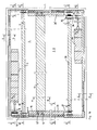
- FIG. 1 shows a preferred embodiment of the insulating glass arrangement according to the invention with a spacer 1, two panes 2, 3 and a sun protection film 4.
- An electric motor 5 is used as the drive device and two spiral springs 6, 6 'serve as the counter-pulling device.
- the sun protection film 4 is wound onto a rotatable shaft 7 coupled to the electric motor 5.
- the coupling between the electric motor 5 and the rotatable shaft takes place via a toothed belt arrangement consisting of two toothed belt pulleys 8, 9 and a toothed belt 10.
- the lower part of the sun protection film 4 ends with a closing rod 11, which is connected to the spiral springs 6, 6 'at the left and right ends via an angle element 12, 12'.
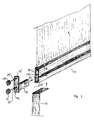
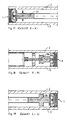
- Fig. 2 shows more details of the end rod 11.
- the end rod consists of two elongated half parts 17, 18 with approximately U-profile.
- the half parts 17, 18 can be plugged into one another, the shape of the U-profile together with an overlap 19 providing a snap connection, into which the lower edge of the sun protection film 4 can also be clamped.
- the elongated half part 18 additionally has a web 20, through which a channel 21 extending along the half part 18 is created, which serves to receive an end piece 13.
- the end piece 13 has two journals 14, 14 ', on which two rollers 15, 15' can be attached.
- the rollers 15, 15 ' run in a guide rail 16 (see FIG. 1 or section CC in FIG. 5).
- the bearing pins 14, 14 ' have two nipple extensions 21, 21', with which trouble-free and, in particular, tilt-free running of the rollers 15, 15 'in the guide rail 16 is achieved.
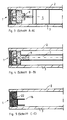
- 3 and 4 show the mounting of the toothed belt pulleys 8 and 9 in the spacer 1 and the connection of these toothed belt pulleys with the electric motor 5 and the rotatable shaft 7.
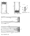
- Fig. 5 shows the shape of the guide rail 16. It consists of a U-longitudinal profile with an extension 22 with which it can be inserted into the spacer 1. For this purpose, the spacer is designed in two pieces at this point.
- Fig. 8 shows the end rod 11 together with the sun protection film 4 clamped in the snap device in cross section.
- roller spring 6, 6 used as a counter-pulling device, with a spring housing 24 and a spring winding 23 and a spring core 25, around which the spring steel lies loosely.
- FIG. 12 is an overall view corresponding to FIG. 1 of an insulating glass arrangement according to the invention, however, in deviation from this, the counter-pulling device is formed by a torsion spring 27, with pull cables 26, 26 ', which are wound on the one hand on the torsion spring 27 and on the other hand connected to the end rod 11.
- FIGS. 13 and 14 are sectional drawings along lines II and JJ according to FIG. 12 and show a bearing journal 28 for the spring shaft and a fastening element 29 for the torsion spring 27.
- torsion spring 27 which is currently particularly preferably used as a counter-pulling device and shows a spring shaft 30 which is arranged in an aluminum tube 32.
- the traction cables 26, 26 ' are wound at the two ends of the aluminum tube 32, lateral guides 30, 31' for the traction cables 26, 26 'being placed on the aluminum tube 32.
- FIG. 16 shows a further overall view of an embodiment of the insulating glass arrangement according to the invention with an electrically operated counter-pulling device.
- the figure shows a counter-pull motor 33 with a further toothed belt arrangement, consisting of two pulleys 34, 35 and a toothed belt 36, the same part being preferably used for the toothed belt 36 and the toothed belt 10.
- the toothed belt arrangement 34, 35, 36 acts on a winding shaft 38, on which the pull cables 26, 26 'can be wound in this embodiment.
- FIGS. 17 to 19 show sectional drawings along the lines KK, MM and LL according to FIG. 16.
- the toothed belt disks 34 and 35 (FIGS. 18 and 19) and (FIG. 17 ) a journal 37 for supporting the winding shaft 38.
Landscapes
- Engineering & Computer Science (AREA)
- Structural Engineering (AREA)
- Architecture (AREA)
- Civil Engineering (AREA)
- Blinds (AREA)
- Operating, Guiding And Securing Of Roll- Type Closing Members (AREA)
- Securing Of Glass Panes Or The Like (AREA)
- Joining Of Glass To Other Materials (AREA)
- Gas-Filled Discharge Tubes (AREA)
- Inorganic Insulating Materials (AREA)
- Table Devices Or Equipment (AREA)
Claims (16)
- Système de vitres isolantes, en particulier pour montage incliné ou horizontal, comprenant une entretoise (1), deux vitres (2, 3), un film pare-soleil (4) qui est disposé entre les vitres (2, 3) et peut être déplacé vers le haut et vers le bas, un dispositif d'entraînement (5) agissant sur le film pare-soleil (4) dans le sens ascendant ainsi qu'un dispositif de contre-traction (6) agissant sur ledit film pare-soleil (4) dans le sens descendant, caractérisé en ce que les vitres (2, 3) sont assemblées par collage avec l'entretoise (1), et le film pare-soleil (4) comporte, sur sa limite inférieure, une barre d'extrémité (11) qui absorbe la force du dispositif de contre-traction (6), la barre d'extrémité (11) étant formée de deux moitiés allongées emboîtables (17, 18) à profil sensiblement en U qui, une fois emboîtées, réalisent une fermeture encliquetée dans laquelle est immobilisé le bord inférieur du film pare-soleil (4).
- Système de vitres isolantes selon la revendication 1, caractérisé par un arbre tournant (7) accouplé au dispositif d'entraînement (5) et destiné à enrouler le film pare-soleil (4) lors du mouvement ascendant.
- Système de vitres isolantes selon la revendication 1, caractérisé en ce que, lors du mouvement ascendant, le film pare-soleil (4) peut être replié en forme de zigzag grâce à un pré-pliage opposé alterné.
- Système de vitres isolantes selon les revendications précédentes, caractérisé en ce que le dispositif de contre-traction (6) est un élément élastique.
- Système de vitres isolantes selon la revendication 4, caractérisé en ce que l'élément élastique est une barre élastique.
- Système de vitres isolantes selon la revendication 5, caractérisé en ce que la barre élastique est un ressort de torsion (27).
- Système de vitres isolantes selon la revendication 4, caractérisé en ce que l'élément élastique est formé par un moins un ressort déroulant (23, 24, 25).
- Système de vitres isolantes selon la revendication 7, caractérisé en ce que le ressort déroulant, au nombre d'au moins un, possède une force élastique comprise entre 1,5 à 4 N.
- Système de vitres isolantes selon les revendications 1 à 3, caractérisé en ce que le dispositif de contre-traction (6) est entraîné par un moteur électrique de contre-traction (33).
- Système de vitres isolantes selon les revendications 6 ou 9, caractérisé en ce que le dispositif de contre-traction (6) comporte des câbles de traction (26, 26') qui agissent sur le film pare-soleil (4) et qui peuvent être enroulés sur le ressort de torsion (27) ou sur un arbre d'enroulement (38) entraîné par le moteur de contre-traction (33).
- Système de vitres isolantes selon les revendications 1 à 3, caractérisé en ce que le dispositif de contre-traction (6) est formé par un câble de traction qui est dévié en dessous du film pare-soleil (4) et revient au dispositif d'entraînement (5).
- Système de vitres isolantes selon les revendications précédentes, caractérisé en ce que le dispositif d'entraînement (5) est un moteur électrique.
- Système de vitres isolantes selon la revendication 12, caractérisé en ce que l'arbre du moteur et l'arbre tournant (7) sont parallèles entre eux et sont accouplés à un dispositif à courroie dentée (8, 9, 10).
- Système de vitres isolantes selon les revendications précédentes, caractérisé en ce que le film pare-soleil (4) est un film métallique doublé de matière plastique sur ses deux faces.
- Système de vitres isolantes selon la revendication 14, caractérisé en ce que le film métallique est un film d'aluminium ou de cuivre d'une épaisseur de 20 à 100 nm, et la doublure en matière plastique est une doublure en polyester d'une épaisseur de 10 à 80 »m.
- Mise en oeuvre d'un système de vitres isolantes à dispositif de contre-traction selon les revendications précédentes pour un montage incliné ou horizontal.
Applications Claiming Priority (2)
| Application Number | Priority Date | Filing Date | Title |
|---|---|---|---|
| DE4031031A DE4031031A1 (de) | 1990-10-01 | 1990-10-01 | Isolierglasanordnung |
| DE4031031 | 1990-10-01 |
Publications (2)
| Publication Number | Publication Date |
|---|---|
| EP0483528A1 EP0483528A1 (fr) | 1992-05-06 |
| EP0483528B1 true EP0483528B1 (fr) | 1995-03-29 |
Family
ID=6415368
Family Applications (1)
| Application Number | Title | Priority Date | Filing Date |
|---|---|---|---|
| EP91116631A Expired - Lifetime EP0483528B1 (fr) | 1990-10-01 | 1991-09-27 | Système de vitres isolantes |
Country Status (3)
| Country | Link |
|---|---|
| EP (1) | EP0483528B1 (fr) |
| AT (1) | ATE120517T1 (fr) |
| DE (2) | DE4031031A1 (fr) |
Families Citing this family (30)
| Publication number | Priority date | Publication date | Assignee | Title |
|---|---|---|---|---|
| DE19514019C2 (de) | 1995-04-13 | 1997-02-13 | Schmidt Manfred | Rollo-Folie und Herstellverfahren |
| DE19605273C2 (de) * | 1996-02-13 | 2000-08-31 | Horst H Goldner | Rollo mit einem auf eine Wickelwelle auf- und von dieser abwickelbaren Wickelmedium |
| DE19610268C2 (de) * | 1996-03-15 | 2001-05-23 | Consafis Glas Conzelmann Gmbh | Rolloeinrichtung für ein Isolierglaselement |
| DE19737632C2 (de) * | 1997-08-28 | 2000-04-20 | Horst H Goldner | Kombinierte Rollo- und Jalousieabdeckvorrichtung für eine Fensteröffnung |
| DE19943243A1 (de) * | 1999-09-10 | 2001-04-05 | Daimler Chrysler Ag | Sonnenschutzeinrichtung für Fensterscheiben von Fahrzeugen |
| DE10041540A1 (de) * | 2000-01-20 | 2001-07-26 | Michael Mayr | Isolierglasscheibe mit integrierter Rolloeinrichtung |
| DE20021691U1 (de) | 2000-01-20 | 2001-04-12 | Lutz, Franz, 86657 Bissingen | Isolierglasscheibe mit integrierter Rolloeinrichtung |
| WO2002014642A1 (fr) * | 2000-08-16 | 2002-02-21 | Eae Patent-Und Lizenzmarketing Gmbh | Ensemble pour vitrage avec guidage de store a lamelles integre, elements d'assemblage et arbre d'enroulement et de rotation a deplacement axial |
| DE20016562U1 (de) | 2000-09-21 | 2000-12-14 | Schmidt, Manfred, Dipl.-Phys., 71101 Schönaich | Isolierglasanordnung für Folien-Rollo |
| DE20209724U1 (de) * | 2001-07-03 | 2002-11-14 | Lutz, Franz, 86657 Bissingen | Isolierglasscheibe mit integrierter, motorisch angetriebener Sonnenschutz- oder Verdunklungsblende |
| DE10232536B4 (de) | 2002-07-18 | 2004-09-30 | Philipp Tussinger | Rollovorrichtung |
| CN1699723A (zh) * | 2004-05-17 | 2005-11-23 | 王仲明 | 一类电机滚动卷帘的制作方法 |
| EP1801344A3 (fr) * | 2005-12-23 | 2011-07-06 | Techno Glas Sagl. | Double vitrage sous vide pour ouvertures dans bâtiments |
| DE502006002324D1 (de) | 2006-03-29 | 2009-01-22 | Schmidt Manfred | Rollo mit Seilzugsystem |
| WO2008025554A2 (fr) * | 2006-08-30 | 2008-03-06 | Simon Lutz | élément de vitrage isolant dans lequel une feuille mobile de protection solaire ou de protection contre la vue est intégrée |
| DE102007030357B4 (de) * | 2007-06-29 | 2009-09-03 | Visio-Glas Gmbh Isolierglaswerk | Rollo mit Spannvorrichtung sowie Mehrscheiben-Isolierglaselement mit einem solchen Rollo |
| DE102008032677A1 (de) * | 2008-07-12 | 2010-03-04 | Franz Eduard Pollich | Beschattungsvorrichtung für ein faltenfreies Auf- und Abrollen einer Beschattungsfolie |
| DE202008015917U1 (de) * | 2008-12-02 | 2010-04-22 | Inalfa Roof Systems Group B.V. | Scheibenanordnung |
| DE102009009504B3 (de) * | 2009-02-18 | 2010-04-01 | Marcel Kunz | Mehrscheiben-Isolierglas |
| DE202009005021U1 (de) | 2009-07-14 | 2009-12-03 | Kindermann, Ingmar | Rolloeinrichtung im Zwischenraum einer Isolierglasscheibeneinheit |
| EP2626496A1 (fr) | 2012-02-10 | 2013-08-14 | Technoform Glass Insulation Holding GmbH | Profil d'espaceur pour cadre d'espaceur pour une unité de verre isolant avec éléments d'intervalle et unité de verre isolant |
| DE102013000397A1 (de) * | 2013-01-11 | 2014-07-17 | ScreenTronic GmbH | Jalousiesystem |
| DE102013000396A1 (de) * | 2013-01-11 | 2014-07-17 | ScreenTronic GmbH | Jalousiesystem |
| CN108590485A (zh) * | 2018-06-01 | 2018-09-28 | 江苏赛迪乐节能科技有限公司 | 用于中空百叶玻璃的翻转固定装置及中空百叶玻璃 |
| DE102022129359A1 (de) | 2022-11-07 | 2024-05-08 | Küster Holding Gesellschaft mit beschränkter Haftung | Isolierglasanordnung |
| DE102022129360A1 (de) | 2022-11-07 | 2024-05-08 | Küster Holding Gesellschaft mit beschränkter Haftung | Isolierglasanordnung |
| DE102022129358A1 (de) | 2022-11-07 | 2024-05-08 | Küster Holding Gesellschaft mit beschränkter Haftung | Isolierglasanordnung |
| DE102022129357A1 (de) | 2022-11-07 | 2024-05-08 | Küster Holding Gesellschaft mit beschränkter Haftung | Isolierglasanordnung |
| DE202024100283U1 (de) | 2024-01-19 | 2024-02-22 | Küster Holding Gesellschaft mit beschränkter Haftung | Isolierglasanordnung |
| DE202024100340U1 (de) | 2024-01-23 | 2024-02-14 | Küster Holding Gesellschaft mit beschränkter Haftung | Isolierglasanordnung |
Family Cites Families (5)
| Publication number | Priority date | Publication date | Assignee | Title |
|---|---|---|---|---|
| DE2842381A1 (de) * | 1978-09-29 | 1980-04-03 | Paul Baier | Rolladen fuer dachfenster in schwenkfluegelbauweise |
| DE7904967U1 (de) * | 1979-02-22 | 1990-03-01 | Velux GmbH - Bauzubehör, 2000 Hamburg | Rolladen |
| DE3219509A1 (de) * | 1982-05-25 | 1983-12-01 | Pusch, Günter, Dr.-Ing., 6903 Neckargemünd | Materialbahn zur thermischen isolation in den luftspalten von gebaeudewaenden |
| DE8612445U1 (de) * | 1986-05-06 | 1986-07-31 | Johann Hilberer GmbH, 7600 Offenburg | Rolladen mit Federzug |
| GB2219335B (en) * | 1988-06-03 | 1992-01-02 | Hunter Douglas Ind Bv | A multiple glazed window unit |
-
1990
- 1990-10-01 DE DE4031031A patent/DE4031031A1/de not_active Withdrawn
-
1991
- 1991-09-27 EP EP91116631A patent/EP0483528B1/fr not_active Expired - Lifetime
- 1991-09-27 DE DE59105044T patent/DE59105044D1/de not_active Expired - Fee Related
- 1991-09-27 AT AT91116631T patent/ATE120517T1/de not_active IP Right Cessation
Also Published As
| Publication number | Publication date |
|---|---|
| DE59105044D1 (de) | 1995-05-04 |
| DE4031031A1 (de) | 1992-04-02 |
| ATE120517T1 (de) | 1995-04-15 |
| EP0483528A1 (fr) | 1992-05-06 |
Similar Documents
| Publication | Publication Date | Title |
|---|---|---|
| EP0483528B1 (fr) | Système de vitres isolantes | |
| DE69818928T2 (de) | Kombinierte Mehrfachverglasung und Lichtsteuerungsvorrichtung | |
| DE19514019C2 (de) | Rollo-Folie und Herstellverfahren | |
| DE4015215A1 (de) | Hubtor mit einem lamellenpanzer in fuehrungsbahnen | |
| EP1191183B1 (fr) | Système de vitres isolantes avec store à enrouleur en forme de feuille | |
| DE102009045746A1 (de) | Rolloanordnung mit wengistens einer Wickelwelle und einem Vorhangelement sowie Glaseinheit und Verfahren zum Auf- und/oder Abwickeln eines Vorhangelements von einer Wickelwelle | |
| DE102013001176A1 (de) | lsolationsvorrichtung für Fenster | |
| DE3743366A1 (de) | Waermerollo mit seitlicher magnetbandfuehrung | |
| DE9117067U1 (de) | Fensterjalousie | |
| EP2896763B1 (fr) | Dispositif de protection pivotant extensible | |
| EP1251235B1 (fr) | Lamelle pour une porte industrielle, porte industrielle et procédé de fabrication d'une telle lamelle | |
| EP4455442A2 (fr) | Vitrage isolant avec panneau solaire intégré | |
| DE9400852U1 (de) | Zum dosierten Einlassen von Licht in einen Raum dienende Beschattungseinrichtung mit Lamellen | |
| DE3442709C2 (de) | Betätigungsvorrichtung für einen Rolladen für ein Dachfenster | |
| EP0358920B1 (fr) | Volets roulants | |
| AT1391U1 (de) | Behang zur abdunkelung von fensteröffnungen | |
| DE29711513U1 (de) | Fenster oder Türe mit einer Doppelverglasung und einer dritten, außenliegenden Scheibe | |
| EP1172514A2 (fr) | Protection solaire située à l'extérieur | |
| DE102021210642A1 (de) | Verdunklungselement mit Heizelement | |
| DE20301691U1 (de) | Einrichtung zum wärmeverlustarmen Belüften von Räumen über eine oder mehrere Fenster/Tür-Rolladen-Anordnung | |
| EP0087806B1 (fr) | Volet roulant pour la couverture hermétique des ouvertures dans des murs par la formation d'au moins une couche d'air immobile | |
| DE29814826U1 (de) | Jalousie mit geteilten Lamellen | |
| DE19839332A1 (de) | Multifunktionsrolladen | |
| AT363239B (de) | Rafflamellenstore | |
| DE3000112A1 (de) | Einrichtung zur innenausstattung |
Legal Events
| Date | Code | Title | Description |
|---|---|---|---|
| PUAI | Public reference made under article 153(3) epc to a published international application that has entered the european phase |
Free format text: ORIGINAL CODE: 0009012 |
|
| AK | Designated contracting states |
Kind code of ref document: A1 Designated state(s): AT BE CH DE FR IT LI LU NL |
|
| 17P | Request for examination filed |
Effective date: 19920919 |
|
| 17Q | First examination report despatched |
Effective date: 19930302 |
|
| GRAA | (expected) grant |
Free format text: ORIGINAL CODE: 0009210 |
|
| AK | Designated contracting states |
Kind code of ref document: B1 Designated state(s): AT BE CH DE FR IT LI LU NL |
|
| PG25 | Lapsed in a contracting state [announced via postgrant information from national office to epo] |
Ref country code: NL Free format text: LAPSE BECAUSE OF NON-PAYMENT OF DUE FEES Effective date: 19950329 Ref country code: IT Free format text: LAPSE BECAUSE OF FAILURE TO SUBMIT A TRANSLATION OF THE DESCRIPTION OR TO PAY THE FEE WITHIN THE PRE;WARNING: LAPSES OF ITALIAN PATENTS WITH EFFECTIVE DATE BEFORE 2007 MAY HAVE OCCURRED AT ANY TIME BEFORE 2007. THE CORRECT EFFECTIVE DATE MAY BE DIFFERENT FROM THE ONE RECORDED.SCRIBED TIME-LIMIT Effective date: 19950329 Ref country code: FR Effective date: 19950329 Ref country code: BE Effective date: 19950329 |
|
| REF | Corresponds to: |
Ref document number: 120517 Country of ref document: AT Date of ref document: 19950415 Kind code of ref document: T |
|
| REF | Corresponds to: |
Ref document number: 59105044 Country of ref document: DE Date of ref document: 19950504 |
|
| EN | Fr: translation not filed | ||
| NLV1 | Nl: lapsed or annulled due to failure to fulfill the requirements of art. 29p and 29m of the patents act | ||
| PG25 | Lapsed in a contracting state [announced via postgrant information from national office to epo] |
Ref country code: LU Free format text: LAPSE BECAUSE OF NON-PAYMENT OF DUE FEES Effective date: 19950930 |
|
| PLBI | Opposition filed |
Free format text: ORIGINAL CODE: 0009260 |
|
| 26 | Opposition filed |
Opponent name: AGERO AG. Effective date: 19951012 |
|
| PLBF | Reply of patent proprietor to notice(s) of opposition |
Free format text: ORIGINAL CODE: EPIDOS OBSO |
|
| PLBF | Reply of patent proprietor to notice(s) of opposition |
Free format text: ORIGINAL CODE: EPIDOS OBSO |
|
| PLBF | Reply of patent proprietor to notice(s) of opposition |
Free format text: ORIGINAL CODE: EPIDOS OBSO |
|
| PGFP | Annual fee paid to national office [announced via postgrant information from national office to epo] |
Ref country code: CH Payment date: 19960923 Year of fee payment: 6 |
|
| PLBL | Opposition procedure terminated |
Free format text: ORIGINAL CODE: EPIDOS OPPC |
|
| PLBM | Termination of opposition procedure: date of legal effect published |
Free format text: ORIGINAL CODE: 0009276 |
|
| STAA | Information on the status of an ep patent application or granted ep patent |
Free format text: STATUS: OPPOSITION PROCEDURE CLOSED |
|
| 27C | Opposition proceedings terminated |
Effective date: 19970424 |
|
| PG25 | Lapsed in a contracting state [announced via postgrant information from national office to epo] |
Ref country code: CH Free format text: LAPSE BECAUSE OF NON-PAYMENT OF DUE FEES Effective date: 19970930 Ref country code: LI Free format text: LAPSE BECAUSE OF NON-PAYMENT OF DUE FEES Effective date: 19970930 |
|
| REG | Reference to a national code |
Ref country code: CH Ref legal event code: PL |
|
| PGFP | Annual fee paid to national office [announced via postgrant information from national office to epo] |
Ref country code: AT Payment date: 20030922 Year of fee payment: 13 |
|
| PGFP | Annual fee paid to national office [announced via postgrant information from national office to epo] |
Ref country code: DE Payment date: 20040309 Year of fee payment: 13 |
|
| PG25 | Lapsed in a contracting state [announced via postgrant information from national office to epo] |
Ref country code: AT Free format text: LAPSE BECAUSE OF NON-PAYMENT OF DUE FEES Effective date: 20040927 |
|
| PG25 | Lapsed in a contracting state [announced via postgrant information from national office to epo] |
Ref country code: DE Free format text: LAPSE BECAUSE OF NON-PAYMENT OF DUE FEES Effective date: 20050401 |