EP0483561A1 - Procédé et dispositif d'usinage - Google Patents
Procédé et dispositif d'usinage Download PDFInfo
- Publication number
- EP0483561A1 EP0483561A1 EP91117202A EP91117202A EP0483561A1 EP 0483561 A1 EP0483561 A1 EP 0483561A1 EP 91117202 A EP91117202 A EP 91117202A EP 91117202 A EP91117202 A EP 91117202A EP 0483561 A1 EP0483561 A1 EP 0483561A1
- Authority
- EP
- European Patent Office
- Prior art keywords
- coolant
- workpiece
- machining
- pressurized fluid
- operative
- Prior art date
- Legal status (The legal status is an assumption and is not a legal conclusion. Google has not performed a legal analysis and makes no representation as to the accuracy of the status listed.)
- Granted
Links
- 238000003754 machining Methods 0.000 title claims abstract description 51
- 238000000034 method Methods 0.000 title claims abstract description 23
- 239000002826 coolant Substances 0.000 claims abstract description 68
- 239000012530 fluid Substances 0.000 claims abstract description 45
- 230000003247 decreasing effect Effects 0.000 claims abstract description 8
- 238000000227 grinding Methods 0.000 claims description 35
- 239000000203 mixture Substances 0.000 claims description 14
- CURLTUGMZLYLDI-UHFFFAOYSA-N Carbon dioxide Chemical compound O=C=O CURLTUGMZLYLDI-UHFFFAOYSA-N 0.000 claims description 10
- 239000000411 inducer Substances 0.000 claims description 10
- 229910002092 carbon dioxide Inorganic materials 0.000 claims description 5
- 239000001569 carbon dioxide Substances 0.000 claims description 5
- 239000011248 coating agent Substances 0.000 claims description 4
- 238000000576 coating method Methods 0.000 claims description 4
- 229910003460 diamond Inorganic materials 0.000 claims description 4
- 239000010432 diamond Substances 0.000 claims description 4
- 229910052582 BN Inorganic materials 0.000 claims description 3
- PZNSFCLAULLKQX-UHFFFAOYSA-N Boron nitride Chemical compound N#B PZNSFCLAULLKQX-UHFFFAOYSA-N 0.000 claims description 3
- 230000002708 enhancing effect Effects 0.000 abstract description 2
- XLYOFNOQVPJJNP-UHFFFAOYSA-N water Substances O XLYOFNOQVPJJNP-UHFFFAOYSA-N 0.000 description 10
- 239000003208 petroleum Substances 0.000 description 7
- 239000000463 material Substances 0.000 description 5
- 239000007788 liquid Substances 0.000 description 4
- 239000007791 liquid phase Substances 0.000 description 4
- 238000001816 cooling Methods 0.000 description 3
- 230000001965 increasing effect Effects 0.000 description 3
- 239000000314 lubricant Substances 0.000 description 3
- 230000001050 lubricating effect Effects 0.000 description 3
- 239000002245 particle Substances 0.000 description 3
- RYGMFSIKBFXOCR-UHFFFAOYSA-N Copper Chemical compound [Cu] RYGMFSIKBFXOCR-UHFFFAOYSA-N 0.000 description 2
- XEEYBQQBJWHFJM-UHFFFAOYSA-N Iron Chemical compound [Fe] XEEYBQQBJWHFJM-UHFFFAOYSA-N 0.000 description 2
- 229910052802 copper Inorganic materials 0.000 description 2
- 239000010949 copper Substances 0.000 description 2
- 238000009826 distribution Methods 0.000 description 2
- 238000007710 freezing Methods 0.000 description 2
- 230000008014 freezing Effects 0.000 description 2
- 239000007789 gas Substances 0.000 description 2
- 230000020169 heat generation Effects 0.000 description 2
- 229920013639 polyalphaolefin Polymers 0.000 description 2
- ZAMOUSCENKQFHK-UHFFFAOYSA-N Chlorine atom Chemical compound [Cl] ZAMOUSCENKQFHK-UHFFFAOYSA-N 0.000 description 1
- 229910000640 Fe alloy Inorganic materials 0.000 description 1
- OAICVXFJPJFONN-UHFFFAOYSA-N Phosphorus Chemical compound [P] OAICVXFJPJFONN-UHFFFAOYSA-N 0.000 description 1
- 229910000831 Steel Inorganic materials 0.000 description 1
- NINIDFKCEFEMDL-UHFFFAOYSA-N Sulfur Chemical compound [S] NINIDFKCEFEMDL-UHFFFAOYSA-N 0.000 description 1
- RTAQQCXQSZGOHL-UHFFFAOYSA-N Titanium Chemical compound [Ti] RTAQQCXQSZGOHL-UHFFFAOYSA-N 0.000 description 1
- 206010006514 bruxism Diseases 0.000 description 1
- 230000015556 catabolic process Effects 0.000 description 1
- 239000000460 chlorine Substances 0.000 description 1
- 229910052801 chlorine Inorganic materials 0.000 description 1
- 230000002860 competitive effect Effects 0.000 description 1
- 238000005260 corrosion Methods 0.000 description 1
- 230000007797 corrosion Effects 0.000 description 1
- 238000005520 cutting process Methods 0.000 description 1
- 238000006731 degradation reaction Methods 0.000 description 1
- 239000000839 emulsion Substances 0.000 description 1
- 238000001914 filtration Methods 0.000 description 1
- 238000005087 graphitization Methods 0.000 description 1
- 229910052742 iron Inorganic materials 0.000 description 1
- 229910052751 metal Inorganic materials 0.000 description 1
- 239000002184 metal Substances 0.000 description 1
- 238000005555 metalworking Methods 0.000 description 1
- 230000003647 oxidation Effects 0.000 description 1
- 238000007254 oxidation reaction Methods 0.000 description 1
- 230000036961 partial effect Effects 0.000 description 1
- 239000012071 phase Substances 0.000 description 1
- 229910052698 phosphorus Inorganic materials 0.000 description 1
- 239000011574 phosphorus Substances 0.000 description 1
- 239000007787 solid Substances 0.000 description 1
- 239000010959 steel Substances 0.000 description 1
- 239000000126 substance Substances 0.000 description 1
- 229910052717 sulfur Inorganic materials 0.000 description 1
- 239000011593 sulfur Substances 0.000 description 1
- 230000008719 thickening Effects 0.000 description 1
- 239000010936 titanium Substances 0.000 description 1
- 229910052719 titanium Inorganic materials 0.000 description 1
- 150000003626 triacylglycerols Chemical class 0.000 description 1
- 238000009834 vaporization Methods 0.000 description 1
- 230000008016 vaporization Effects 0.000 description 1
Images

Classifications
-
- B—PERFORMING OPERATIONS; TRANSPORTING
- B23—MACHINE TOOLS; METAL-WORKING NOT OTHERWISE PROVIDED FOR
- B23Q—DETAILS, COMPONENTS, OR ACCESSORIES FOR MACHINE TOOLS, e.g. ARRANGEMENTS FOR COPYING OR CONTROLLING; MACHINE TOOLS IN GENERAL CHARACTERISED BY THE CONSTRUCTION OF PARTICULAR DETAILS OR COMPONENTS; COMBINATIONS OR ASSOCIATIONS OF METAL-WORKING MACHINES, NOT DIRECTED TO A PARTICULAR RESULT
- B23Q11/00—Accessories fitted to machine tools for keeping tools or parts of the machine in good working condition or for cooling work; Safety devices specially combined with or arranged in, or specially adapted for use in connection with, machine tools
- B23Q11/10—Arrangements for cooling or lubricating tools or work
-
- B—PERFORMING OPERATIONS; TRANSPORTING
- B23—MACHINE TOOLS; METAL-WORKING NOT OTHERWISE PROVIDED FOR
- B23Q—DETAILS, COMPONENTS, OR ACCESSORIES FOR MACHINE TOOLS, e.g. ARRANGEMENTS FOR COPYING OR CONTROLLING; MACHINE TOOLS IN GENERAL CHARACTERISED BY THE CONSTRUCTION OF PARTICULAR DETAILS OR COMPONENTS; COMBINATIONS OR ASSOCIATIONS OF METAL-WORKING MACHINES, NOT DIRECTED TO A PARTICULAR RESULT
- B23Q11/00—Accessories fitted to machine tools for keeping tools or parts of the machine in good working condition or for cooling work; Safety devices specially combined with or arranged in, or specially adapted for use in connection with, machine tools
- B23Q11/10—Arrangements for cooling or lubricating tools or work
- B23Q11/1038—Arrangements for cooling or lubricating tools or work using cutting liquids with special characteristics, e.g. flow rate, quality
- B23Q11/1053—Arrangements for cooling or lubricating tools or work using cutting liquids with special characteristics, e.g. flow rate, quality using the cutting liquid at specially selected temperatures
-
- B—PERFORMING OPERATIONS; TRANSPORTING
- B23—MACHINE TOOLS; METAL-WORKING NOT OTHERWISE PROVIDED FOR
- B23F—MAKING GEARS OR TOOTHED RACKS
- B23F21/00—Tools specially adapted for use in machines for manufacturing gear teeth
- B23F21/02—Grinding discs; Grinding worms
- B23F21/023—Face-mill-type, i.e. cup-shaped, grinding wheels
-
- B—PERFORMING OPERATIONS; TRANSPORTING
- B23—MACHINE TOOLS; METAL-WORKING NOT OTHERWISE PROVIDED FOR
- B23Q—DETAILS, COMPONENTS, OR ACCESSORIES FOR MACHINE TOOLS, e.g. ARRANGEMENTS FOR COPYING OR CONTROLLING; MACHINE TOOLS IN GENERAL CHARACTERISED BY THE CONSTRUCTION OF PARTICULAR DETAILS OR COMPONENTS; COMBINATIONS OR ASSOCIATIONS OF METAL-WORKING MACHINES, NOT DIRECTED TO A PARTICULAR RESULT
- B23Q1/00—Members which are comprised in the general build-up of a form of machine, particularly relatively large fixed members
- B23Q1/0009—Energy-transferring means or control lines for movable machine parts; Control panels or boxes; Control parts
- B23Q1/0018—Energy-transferring means or control lines for movable machine parts; Control panels or boxes; Control parts comprising hydraulic means
- B23Q1/0027—Energy-transferring means or control lines for movable machine parts; Control panels or boxes; Control parts comprising hydraulic means between moving parts between which an uninterrupted energy-transfer connection is maintained
- B23Q1/0036—Energy-transferring means or control lines for movable machine parts; Control panels or boxes; Control parts comprising hydraulic means between moving parts between which an uninterrupted energy-transfer connection is maintained one of those parts being a tool
-
- B—PERFORMING OPERATIONS; TRANSPORTING
- B24—GRINDING; POLISHING
- B24B—MACHINES, DEVICES, OR PROCESSES FOR GRINDING OR POLISHING; DRESSING OR CONDITIONING OF ABRADING SURFACES; FEEDING OF GRINDING, POLISHING, OR LAPPING AGENTS
- B24B55/00—Safety devices for grinding or polishing machines; Accessories fitted to grinding or polishing machines for keeping tools or parts of the machine in good working condition
- B24B55/02—Equipment for cooling the grinding surfaces, e.g. devices for feeding coolant
-
- B—PERFORMING OPERATIONS; TRANSPORTING
- B24—GRINDING; POLISHING
- B24D—TOOLS FOR GRINDING, BUFFING OR SHARPENING
- B24D7/00—Bonded abrasive wheels, or wheels with inserted abrasive blocks, designed for acting otherwise than only by their periphery, e.g. by the front face; Bushings or mountings therefor
- B24D7/10—Bonded abrasive wheels, or wheels with inserted abrasive blocks, designed for acting otherwise than only by their periphery, e.g. by the front face; Bushings or mountings therefor with cooling provisions
-
- Y—GENERAL TAGGING OF NEW TECHNOLOGICAL DEVELOPMENTS; GENERAL TAGGING OF CROSS-SECTIONAL TECHNOLOGIES SPANNING OVER SEVERAL SECTIONS OF THE IPC; TECHNICAL SUBJECTS COVERED BY FORMER USPC CROSS-REFERENCE ART COLLECTIONS [XRACs] AND DIGESTS
- Y10—TECHNICAL SUBJECTS COVERED BY FORMER USPC
- Y10S—TECHNICAL SUBJECTS COVERED BY FORMER USPC CROSS-REFERENCE ART COLLECTIONS [XRACs] AND DIGESTS
- Y10S82/00—Turning
- Y10S82/90—Lathe thermal regulation
Definitions
- This invention relates generally to a method and apparatus for machining a workpiece at high speed while minimizing frictional heat generated during the machining process and more particularly to a method and apparatus that utilizes a temperature responsive coolant cooled by an expanding pressurized fluid such that its physical lubricity progressively increases with decreasing temperature to a consistency operative to reduce frictional heat generated during the machining process and to enhance conductive heat transfer into the machining tool.
- Frictional heat build-up during the machining process can create a plethora of problems including distortion and degradation (including burning) of either or both the workpiece and the machining tool as well as significantly shorten tool life resulting in substantially increased costs associated with machining the particular part.
- One machining process that is particularly prone to heat generation is grinding of which but one example is the grinding of vehicle differential ring gears that is hereinafter described in greater detail as an illustrative example.
- the cooled coolants of the present invention are able to be applied separately or together, commonly at ambient temperature as fluid/liquids or gas/liquids and, as such, can be applied with a high degree of uniform repeatability and, upon returning to ambient temperature, can be cleaned (such as by filtering) for re-use.
- plunge type grinding wheel 100 Another type of grinding wheel that may be utilized to finish grind teeth 3 of ring gear 2 is plunge type grinding wheel 100 hereinafter described in greater detail with respect to FIGURE 4.
- differential ring gears have a plurality of teeth that are characteristically either of the spiral bevel or hypoid type that are circumferentially evenly spaced about the central rotational axis of the gear and face in a direction acutely away therefrom.
- Teeth 3 of ring gear 2 are hypoid type teeth that are curved such that pinion gear 4 is offset from the central rotational axis of ring gear 2 by the distance "d". The distance "d" would be zero in instances where teeth 3 of ring gear 2 are of the spiral bevel type.
- the method and apparatus of the invention involves directing a coolant onto the workpiece whose lubricity progressively increases with decreasing temperature and contacting the coolant with a pressurized fluid that, upon expanding, cools the coolant sufficiently to increase the coolant's physical lubricity to a consistency operative to enhance the coolant's ability to lubricate and reduce frictional heat by a desired amount.
- a pressurized fluid that, upon expanding, cools the coolant sufficiently to increase the coolant's physical lubricity to a consistency operative to enhance the coolant's ability to lubricate and reduce frictional heat by a desired amount.
- the coolant be cooled to a paste-like consistency or even to virtually a solid-like lubricant film as previously described.
- coolant as used in connection with the method and apparatus of the present invention does not include water alone of which a portion is converted to ice particles as disclosed in previously described United States Patent 4,829,859 for such does not possess the characteristic of a progressively increasing lubricity with decreasing temperature especially since water is a solid at 32 o F at standard atmospheric pressure.
- petroleum based coolants suitable for use in connection with present invention include oil and oil emulsions and non-petroleum based coolants which includes synthetic coolants that are water miscible as well as constant phase coolants that are not water miscible such as polyol-esters; poly (alpha-olefins); and triglycerides well known to those skilled in the art of coolants used in connection with machining operations.
- the ability of the coolants in the present invention to exhibit lubricating ability below the freezing point of water is of great advantage for it enables a substantially greater temperature gradient ( ⁇ T) to occur between the interior and the surface of the workpiece that enhances heat conduction away from the region of the workpiece being machined which enables even faster machining to occur.
- pressurized fluid as used in connection with the method and apparatus of the present invention includes pressurized liquids and gases, that upon expanding, while undergoing a reduction in pressure, absorb heat according to their respective latent heat of vaporization characteristics.
- a preferred pressurized fluid is carbon dioxide in the liquid phase.
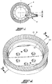
- the present invention includes instances where the coolant and pressurized fluid are separately directed onto the workpiece or are first premixed and then directed onto the workpiece during the machining process. Either one or both of the coolant and pressurized fluid are preferably conveyed through fluid passageways or channel(s) in the machining tool so as to engage the workpiece as close to the machining point as possible such as for example where grooves 10 of teeth 8 of grinding wheel 50 of FIGURE 2 include at least one fluid channel 13 (FIGURE 3) therein for conveying a selected one of the coolant, pressurized fluid, and mixtures thereof (referenced by numeral 16) from an exit 14 to the workpiece as shown in FIGURE 3 .
- grinding wheel 50 would preferably include an annular groove 12 about its inner periphery operative to distribute the selected one of coolant, pressured fluid, and mixtures thereof to other grooves in wheel 50 that include fluid passageways or channels such as channel 13.
- channel 13 In cases where channel 13 is used to convey either the coolant or the pressurized fluid onto the workpiece then the other would be conveyed by other delivery means such as by directing a stream onto the workpiece through suitable conduits or the like.
- FIGURES 3 and 5 Also shown in FIGURES 3 and 5 is an embodiment of an inducer shoe 46 that is of particular advantage in introducing either or both the coolant and pressurized fluid into groove 12 for distribution through channels 13 between teeth 8 to the workpiece being machined in a highly efficient manner.
- Inducer shoe 46 is a stationarily mounted device within the inner periphery of grinding wheel 50 in a suitable manner and has an arcuate face 5 that is adapted to conform to the curvature of groove 12 and has an opening or window 7 that is in registration with groove 12 when inducer shoe 46 is mounted within the inner periphery of grinding wheel 50 so that either or both the coolant and pressurized fluid is able to exit therefrom directly into groove 12 for a distribution after having entered inducer shoe 46 through a suitable conduit connection referenced by numeral 9.
- FIGURE 4 Another embodiment of an inducer shoe 49 is shown in FIGURE 4.
- an annular groove 45 is disposed in the top side (opposite side of wheel 100 side facing way from teeth 20) and inducer shoe 49 is secured against movement relative grinding wheel 50 and includes an opening (not referenced) in registration with groove 45 for conveyance of either or both coolant and pressurized fluid thereto.
- the face of inducer shoe 49 is curved to conform with the curvature of groove 45.
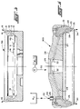
- Plunge type grinding wheel 100 of FIGURE 4 is a cup type wheel illustrating how a mixture of coolant and pressurized fluid can be delivered to the workpiece. Grinding wheel 100 also illustrates how additional elements can be utilized to increase rotational speed of the grinding wheel such as by making the body of the wheel, all except for teeth 20, from a light weight high strength material such as titanium in addition to thickening the central hub region such as referenced by numeral 28 to enhance strength for high speed rotation.
- Teeth 20 are preferably secured to the body as inserts of standard steel that are coated with a layer 23 of cubic boron nitride material that, in addition to providing superior grinding surface characteristics (particularly between about 60 to 180 grit), has a thermal diffusivity factor of about 80 times that of copper and a thermal conductivity of about five times the copper and thus is able to markedly enhance conductance of heat away from the machining location.
- Diamond that heretofor has required lower speed grinding because of frictional heat in conjunction with iron contained in the workpiece has catalyzed oxidation or graphitization of the diamond leading to embrittlement and early failure.
- Diamond when used as a cutting or abrasive coating in conjunction with the present invention, is greatly advantageous for it is harder and has greater heat conductivity than cubic boron nitride.
- Plunge type grinding wheel 100 of FIGURE 4 has a fluid channel or passageway 26 extending through the region 22 between teeth 20 that includes the groove at which exit 25 is located.
- Channel 26 is operative to receive pressurized fluid 30 from pressure reservoir "R2" that may, for example, be pressurized tanks of carbon dioxide in the liquid phase.
- Grinding wheel 100 also includes fluid channels or passageways 32 that extend from bore 29 and intersect channel 26 as shown in FIGURE 4.
- Channels 24 are operative to convey coolant therethrough referenced by numeral 32 that is preferably pumped by pump “P1" from reservoir “R1” and joins pressurized fluid 30 within grinding wheel 100 and exits at exit 25 as a mixture of the coolant 32 and pressurized fluid 30 referenced by numeral 34.
- pump “P1” pumped by pump "P1" from reservoir “R1”
- pressurized fluid 30 referenced by numeral 34.
- the reverse may also be utilized where the coolant enters through channel 26 and the pressurized fluid enters through channel 24.
- FIGURE 7 is illustrative of how a shrouding member 36 may be utilized to enclose grinding wheel 50.
- Shroud member 36 is an enclosure, preferably an insulated enclosure, that shrouds the region in which the coolant is cooled by the expanding pressurized fluid on the workpiece.
- Shroud 36 preferably includes a window 38 exposing a portion of teeth 8 of grinding wheel 50 that are exposed for grinding the workpiece.
- shroud 36 includes a plurality of conduits 40 for conveying coolant 42 and pressurized fluid 44 or mixtures thereof onto teeth 8 within shroud 36 for the cooling of the workpiece.
- the invention provides for the delivery of coolant as defined herein and pressurized fluid, such as carbon dioxide in the liquid phase, and/or mixtures thereof, onto the workpiece such that, upon expansion while undergoing a reduction in pressure, cools and progressively increases the coolant's lubricity to a consistency operative to minimize frictional heat build-up during the machining process.
- pressurized fluid such as carbon dioxide in the liquid phase, and/or mixtures thereof
Landscapes
- Engineering & Computer Science (AREA)
- Mechanical Engineering (AREA)
- Physics & Mathematics (AREA)
- Fluid Mechanics (AREA)
- Polishing Bodies And Polishing Tools (AREA)
- Gear Processing (AREA)
- Lubricants (AREA)
- Grinding-Machine Dressing And Accessory Apparatuses (AREA)
Applications Claiming Priority (2)
| Application Number | Priority Date | Filing Date | Title |
|---|---|---|---|
| US07/606,979 US5129190A (en) | 1990-10-31 | 1990-10-31 | Machining and apparatus |
| US606979 | 1990-10-31 |
Publications (2)
| Publication Number | Publication Date |
|---|---|
| EP0483561A1 true EP0483561A1 (fr) | 1992-05-06 |
| EP0483561B1 EP0483561B1 (fr) | 1999-02-24 |
Family
ID=24430305
Family Applications (1)
| Application Number | Title | Priority Date | Filing Date |
|---|---|---|---|
| EP91117202A Expired - Lifetime EP0483561B1 (fr) | 1990-10-31 | 1991-10-09 | Procédé et dispositif d'usinage |
Country Status (7)
| Country | Link |
|---|---|
| US (1) | US5129190A (fr) |
| EP (1) | EP0483561B1 (fr) |
| JP (1) | JPH04261747A (fr) |
| KR (1) | KR960010554B1 (fr) |
| BR (1) | BR9104733A (fr) |
| DE (1) | DE69130914D1 (fr) |
| MX (1) | MX174230B (fr) |
Cited By (13)
| Publication number | Priority date | Publication date | Assignee | Title |
|---|---|---|---|---|
| US5290135A (en) * | 1992-10-28 | 1994-03-01 | The Gleason Works | Rotary ring cutter having coolant distribution and discharge means |
| GB2290997A (en) * | 1994-07-09 | 1996-01-17 | Mtu Muenchen Gmbh | Cooling grinding wheels |
| EP0826461A1 (fr) * | 1996-08-29 | 1998-03-04 | SOCIETE NATIONALE D'ETUDE ET DE CONSTRUCTION DE MOTEURS D'AVIATION -Snecma | Meule de rectification avec arrosage incorpore |
| AT405800B (de) * | 1994-02-24 | 1999-11-25 | Mtu Muenchen Gmbh | Schleifeinrichtung zur bearbeitung von werkstücken |
| EP1184122A1 (fr) * | 2000-09-04 | 2002-03-06 | Honda Giken Kogyo Kabushiki Kaisha | Procédé pour la fabrication des rainures de dents |
| RU2203165C2 (ru) * | 2001-01-03 | 2003-04-27 | Открытое акционерное общество "Научно-производственное объединение "Сатурн" | Устройство для подачи смазочно-охлаждающей жидкости |
| WO2007129122A1 (fr) * | 2006-05-09 | 2007-11-15 | Liverpool Innovative Technology Limited | Outil d'usinage comprenant un systeme de distribution de fluide interne optimise |
| EP2998052A1 (fr) | 2014-09-22 | 2016-03-23 | Roland Geitel | Procede et dispositif de revetement de surface etroite de demi-produits en forme de plaque ou de pieces a usiner |
| WO2017111747A1 (fr) * | 2015-12-23 | 2017-06-29 | Ortadogu Rulman Sanayi Ve Ticaret Anonim Sirketi | Configuration de roues de meulage et de bride de support |
| ITUA20164592A1 (it) * | 2016-06-22 | 2017-12-22 | Biesse Spa | Metodo e sistema per l'adduzione di fluido refrigerante durante la lavorazione di un pezzo mediante una mola a tazza, e mola a tazza in essi utilizzata |
| WO2018033618A1 (fr) * | 2016-08-18 | 2018-02-22 | Aurich Jan C | Procédé permettant de faire fonctionner une machine-outil d'usinage par enlèvement de copeaux et machine-outil d'usinage de pièces par enlèvement de copeaux |
| DE102018101190A1 (de) * | 2018-01-19 | 2019-07-25 | Mas Gmbh | Verfahren zum spanenden Bearbeiten und Werkzeugmaschine |
| AU2020338783B2 (en) * | 2019-08-30 | 2023-09-07 | Guilin Champion Union Diamond Co., Ltd. | Tool cooling mechanism |
Families Citing this family (23)
| Publication number | Priority date | Publication date | Assignee | Title |
|---|---|---|---|---|
| EP0539055B1 (fr) * | 1991-10-09 | 1997-03-12 | Toyota Jidosha Kabushiki Kaisha | Procédé et dispositif pour travailler une pièce à usiner, utilisant un liquide d'usinage en mousse dans l'eviromage du contact entre la pièce à usiner et l'outil de travail |
| US5215135A (en) * | 1992-06-08 | 1993-06-01 | Gerald M. Fisher | Pellitizer methods and apparatus |
| DE19915619A1 (de) * | 1999-04-07 | 2000-10-19 | Multimatic Oberflaechentechnik | Verfahren zum Abführen von Zerspanungsprodukten eines zerspanenden Bearbeitungsverfahrens |
| US6234882B1 (en) * | 1999-05-24 | 2001-05-22 | Advanced Production Manufacturing, Inc. | Surface enhancement system for building blocks |
| AT502503B1 (de) * | 2003-09-04 | 2007-04-15 | Schrottner Gerhard | Ringsystem zur mediumsführung bei schleifscheiben |
| EP1828669A2 (fr) * | 2004-12-13 | 2007-09-05 | Cool Clean Technologies, Inc. | Dispositif pour appliquer une composition cryogenique et procede d'utilisation associe |
| WO2006119047A2 (fr) * | 2005-04-29 | 2006-11-09 | The Regents Of The University Of Michigan | Preparations de lubrifiant pour metaux a base de dioxyde de carbone supercritique |
| US8062094B2 (en) * | 2005-06-29 | 2011-11-22 | Deere & Company | Process of durability improvement of gear tooth flank surface |
| US7384329B2 (en) * | 2006-05-23 | 2008-06-10 | Saint-Gobain Abrasives Technology Company | Coolant delivery system for grinding tools |
| ES2352943B1 (es) * | 2008-09-10 | 2011-10-19 | Ideko, S. Coop | Método de refrigeración-lubricación para el rectificado. |
| US20110250827A1 (en) * | 2010-04-09 | 2011-10-13 | Gran Quartz Trading, Inc. | Power Tool Blade Mount with Radial Fluid Flow Channels |
| DE102013015252A1 (de) * | 2013-09-13 | 2015-03-19 | Gleason-Pfauter Maschinenfabrik Gmbh | Kühlmittelzufuhr und damit ausgestattete Wälzschälmaschine sowie damit ausgeführtes Wälzschälverfahren |
| US9352437B2 (en) * | 2014-10-24 | 2016-05-31 | Velasa Sports, Inc. | Skate blade retention mechanism with jaw guides |
| USD793830S1 (en) | 2015-07-08 | 2017-08-08 | Velasa Sports, Inc. | Skate blade sharpening system |
| US9573236B2 (en) | 2015-05-28 | 2017-02-21 | Velasa Sports, Inc. | Skate blade sharpening system with alignment adjustment using alignment wheel |
| US9566682B2 (en) | 2014-10-24 | 2017-02-14 | Velasa Sports, Inc. | Skate blade retention mechanism |
| US9475175B2 (en) * | 2014-10-24 | 2016-10-25 | Velasa Sports, Inc. | Grinding wheel arbor |
| US9669508B2 (en) | 2014-10-24 | 2017-06-06 | Velasa Sports, Inc. | Grinding wheel with identification tag |
| US9902035B2 (en) | 2014-10-24 | 2018-02-27 | Velasa Sports, Inc. | Compact grinding wheel |
| US10300574B2 (en) | 2014-10-24 | 2019-05-28 | Velasa Sports, Inc. | Skate blade sharpening system |
| CN108326764A (zh) * | 2018-05-03 | 2018-07-27 | 西安增材制造国家研究院有限公司 | 表面电镀磨料内喷润滑液砂轮及包括该砂轮的磨削装置 |
| US11969851B2 (en) | 2020-07-31 | 2024-04-30 | Velasa Sports, Inc. | Skate blade sharpening system |
| US12485339B2 (en) | 2022-10-14 | 2025-12-02 | Velasa Sports, Inc. | Skate blade clamping systems |
Citations (7)
| Publication number | Priority date | Publication date | Assignee | Title |
|---|---|---|---|---|
| US3547350A (en) * | 1968-12-16 | 1970-12-15 | Mc Donnell Douglas Corp | Spraying device |
| DE2900409A1 (de) * | 1978-01-10 | 1979-07-12 | Skf Kugellagerfabriken Gmbh | Verfahren und zugehoerige vorrichtung zum kuehlen von schleifscheiben |
| DE3007709A1 (de) * | 1980-02-29 | 1981-10-01 | Gleitlagertechnik Gmbh, 7000 Stuttgart | Einrichtung zum zufuehren von kuehlmittel bei werkzeugen |
| US4829859A (en) * | 1986-08-29 | 1989-05-16 | Ulticon Systems, Inc. | Method of high speed machining |
| DE3804781A1 (de) * | 1987-02-28 | 1989-06-01 | Zahnradfabrik Friedrichshafen | Schleifscheibe |
| US4929130A (en) * | 1989-06-28 | 1990-05-29 | United Technologies Corporation | Grinding wheel guard apparatus |
| US4951426A (en) * | 1988-08-11 | 1990-08-28 | Honda Giken Kogyo Kabushiki Kaisha | Grinding fluid feeder apparatus |
Family Cites Families (5)
| Publication number | Priority date | Publication date | Assignee | Title |
|---|---|---|---|---|
| US3768212A (en) * | 1970-01-07 | 1973-10-30 | Unison Corp | Grinding machine |
| US4080952A (en) * | 1976-11-26 | 1978-03-28 | Wain Harry C | Rim pump |
| US4621547A (en) * | 1983-02-28 | 1986-11-11 | Yankoff Gerald K | Method and apparatus for machining |
| DE3521510A1 (de) * | 1985-06-14 | 1986-12-18 | Hanns-Heinz 8000 München Peltz | Vorrichtung zur umlauffoerderung fluessigen kuehlmittels |
| US4695208A (en) * | 1985-11-14 | 1987-09-22 | Yankoff Gerald K | Tool holder |
-
1990
- 1990-10-31 US US07/606,979 patent/US5129190A/en not_active Expired - Fee Related
-
1991
- 1991-10-09 EP EP91117202A patent/EP0483561B1/fr not_active Expired - Lifetime
- 1991-10-09 DE DE69130914T patent/DE69130914D1/de not_active Expired - Lifetime
- 1991-10-29 KR KR1019910019034A patent/KR960010554B1/ko not_active Expired - Fee Related
- 1991-10-29 BR BR919104733A patent/BR9104733A/pt not_active IP Right Cessation
- 1991-10-30 MX MX9101850A patent/MX174230B/es unknown
- 1991-10-31 JP JP3311564A patent/JPH04261747A/ja active Pending
Patent Citations (7)
| Publication number | Priority date | Publication date | Assignee | Title |
|---|---|---|---|---|
| US3547350A (en) * | 1968-12-16 | 1970-12-15 | Mc Donnell Douglas Corp | Spraying device |
| DE2900409A1 (de) * | 1978-01-10 | 1979-07-12 | Skf Kugellagerfabriken Gmbh | Verfahren und zugehoerige vorrichtung zum kuehlen von schleifscheiben |
| DE3007709A1 (de) * | 1980-02-29 | 1981-10-01 | Gleitlagertechnik Gmbh, 7000 Stuttgart | Einrichtung zum zufuehren von kuehlmittel bei werkzeugen |
| US4829859A (en) * | 1986-08-29 | 1989-05-16 | Ulticon Systems, Inc. | Method of high speed machining |
| DE3804781A1 (de) * | 1987-02-28 | 1989-06-01 | Zahnradfabrik Friedrichshafen | Schleifscheibe |
| US4951426A (en) * | 1988-08-11 | 1990-08-28 | Honda Giken Kogyo Kabushiki Kaisha | Grinding fluid feeder apparatus |
| US4929130A (en) * | 1989-06-28 | 1990-05-29 | United Technologies Corporation | Grinding wheel guard apparatus |
Cited By (21)
| Publication number | Priority date | Publication date | Assignee | Title |
|---|---|---|---|---|
| US5290135A (en) * | 1992-10-28 | 1994-03-01 | The Gleason Works | Rotary ring cutter having coolant distribution and discharge means |
| WO1994009937A1 (fr) * | 1992-10-28 | 1994-05-11 | The Gleason Works | Outil de coupe annulaire muni d'organes de distribution et de decharge de fluide de refroidissement |
| AU667211B2 (en) * | 1992-10-28 | 1996-03-14 | Gleason Works, The | Rotary ring cutter having coolant distribution and discharge means |
| AT405800B (de) * | 1994-02-24 | 1999-11-25 | Mtu Muenchen Gmbh | Schleifeinrichtung zur bearbeitung von werkstücken |
| GB2290997A (en) * | 1994-07-09 | 1996-01-17 | Mtu Muenchen Gmbh | Cooling grinding wheels |
| GB2290997B (en) * | 1994-07-09 | 1997-10-08 | Mtu Muenchen Gmbh | Grinding device for machining components |
| EP0826461A1 (fr) * | 1996-08-29 | 1998-03-04 | SOCIETE NATIONALE D'ETUDE ET DE CONSTRUCTION DE MOTEURS D'AVIATION -Snecma | Meule de rectification avec arrosage incorpore |
| FR2752762A1 (fr) * | 1996-08-29 | 1998-03-06 | Snecma | Meule de rectification avec arrosage incorpore |
| US5846125A (en) * | 1996-08-29 | 1998-12-08 | Societe Nationale D'etude Et De Construction De Moteurs D'aviation "Snecma" | Truing wheel with incorporated cooling |
| US6520842B2 (en) | 2000-09-04 | 2003-02-18 | Honda Giken Kogyo Kabushiki Kaisha | Method of forming tooth grooves |
| EP1184122A1 (fr) * | 2000-09-04 | 2002-03-06 | Honda Giken Kogyo Kabushiki Kaisha | Procédé pour la fabrication des rainures de dents |
| RU2203165C2 (ru) * | 2001-01-03 | 2003-04-27 | Открытое акционерное общество "Научно-производственное объединение "Сатурн" | Устройство для подачи смазочно-охлаждающей жидкости |
| WO2007129122A1 (fr) * | 2006-05-09 | 2007-11-15 | Liverpool Innovative Technology Limited | Outil d'usinage comprenant un systeme de distribution de fluide interne optimise |
| EP2998052A1 (fr) | 2014-09-22 | 2016-03-23 | Roland Geitel | Procede et dispositif de revetement de surface etroite de demi-produits en forme de plaque ou de pieces a usiner |
| DE102014219064A1 (de) * | 2014-09-22 | 2016-03-24 | Roland Geitel | Verfahren und Vorrichtung zur Schmalflächenbeschichtung von plattenförmigen Halbzeugen oder Werkstücken |
| WO2017111747A1 (fr) * | 2015-12-23 | 2017-06-29 | Ortadogu Rulman Sanayi Ve Ticaret Anonim Sirketi | Configuration de roues de meulage et de bride de support |
| ITUA20164592A1 (it) * | 2016-06-22 | 2017-12-22 | Biesse Spa | Metodo e sistema per l'adduzione di fluido refrigerante durante la lavorazione di un pezzo mediante una mola a tazza, e mola a tazza in essi utilizzata |
| EP3260236A3 (fr) * | 2016-06-22 | 2018-05-16 | Biesse S.p.A. | Procédé et système pour distribuer un liquide de refroidissement pendant l'usinage d'une pièce avec une meule boisseau, ainsi que la meule |
| WO2018033618A1 (fr) * | 2016-08-18 | 2018-02-22 | Aurich Jan C | Procédé permettant de faire fonctionner une machine-outil d'usinage par enlèvement de copeaux et machine-outil d'usinage de pièces par enlèvement de copeaux |
| DE102018101190A1 (de) * | 2018-01-19 | 2019-07-25 | Mas Gmbh | Verfahren zum spanenden Bearbeiten und Werkzeugmaschine |
| AU2020338783B2 (en) * | 2019-08-30 | 2023-09-07 | Guilin Champion Union Diamond Co., Ltd. | Tool cooling mechanism |
Also Published As
| Publication number | Publication date |
|---|---|
| JPH04261747A (ja) | 1992-09-17 |
| KR960010554B1 (ko) | 1996-08-02 |
| BR9104733A (pt) | 1992-06-16 |
| DE69130914D1 (de) | 1999-04-01 |
| KR920007746A (ko) | 1992-05-27 |
| EP0483561B1 (fr) | 1999-02-24 |
| MX174230B (es) | 1994-04-28 |
| US5129190A (en) | 1992-07-14 |
Similar Documents
| Publication | Publication Date | Title |
|---|---|---|
| US5129190A (en) | Machining and apparatus | |
| US5993297A (en) | Superabrasive grinding wheel with integral coolant passage | |
| US5290135A (en) | Rotary ring cutter having coolant distribution and discharge means | |
| US5846125A (en) | Truing wheel with incorporated cooling | |
| Machado et al. | The effect of extremely low lubricant volumes in machining | |
| US8128323B2 (en) | Driven tool assembly | |
| US6123606A (en) | Method and apparatus for grinding | |
| EP1112133B1 (fr) | Outil de coupe | |
| US4921376A (en) | Arbor for mounting a tool to a spindle of a machine tool and a machining method of employing the same | |
| WO1999060079A2 (fr) | Ensemble outil de fraisage cryogenique relie a de l'azote liquide par un raccord rotatif | |
| KR930003657B1 (ko) | 기어형 공구 | |
| US4949813A (en) | Lubrication/coolant delivery system | |
| Graham et al. | Some observations of through-wheel coolant application in grinding | |
| JPH10113867A (ja) | かき取り工具と加工片の間の共同動作領域に冷却潤滑剤を供給する方法及び装置 | |
| JP2000356223A (ja) | 油潤滑軸受構造及びこれを備えるポンプ、変速機、回転駆動機、並びにポンプ設備 | |
| SU872234A1 (ru) | Устройство дл подачи смазочно-охлаждающих жидкостей | |
| CN210704169U (zh) | 一种钢管加工用铁锈打磨装置 | |
| JP3043930B2 (ja) | 潤滑方式 | |
| US6135861A (en) | Shaft polishing method and a shaft produced thereby | |
| SU1431919A1 (ru) | Устройство дл подачи смазочно-охлаждающей жидкости в зону шлифовани | |
| EP0355904B1 (fr) | Broche de meulage et de polissage à paliers hydrostatiques | |
| SU891759A1 (ru) | Смазочно-охлаждающа жидкость дл механической обработки металлов | |
| SU859429A1 (ru) | Смазочно-охлаждающа жидкость дл механической обработки металлов | |
| Salmon | Using Metalworking Fluids in Grinding Processes | |
| RU2035270C1 (ru) | Спиральное сверло |
Legal Events
| Date | Code | Title | Description |
|---|---|---|---|
| PUAI | Public reference made under article 153(3) epc to a published international application that has entered the european phase |
Free format text: ORIGINAL CODE: 0009012 |
|
| AK | Designated contracting states |
Kind code of ref document: A1 Designated state(s): DE ES FR GB IT SE |
|
| 17P | Request for examination filed |
Effective date: 19920509 |
|
| 17Q | First examination report despatched |
Effective date: 19930303 |
|
| APAB | Appeal dossier modified |
Free format text: ORIGINAL CODE: EPIDOS NOAPE |
|
| GRAG | Despatch of communication of intention to grant |
Free format text: ORIGINAL CODE: EPIDOS AGRA |
|
| GRAG | Despatch of communication of intention to grant |
Free format text: ORIGINAL CODE: EPIDOS AGRA |
|
| GRAH | Despatch of communication of intention to grant a patent |
Free format text: ORIGINAL CODE: EPIDOS IGRA |
|
| RAP1 | Party data changed (applicant data changed or rights of an application transferred) |
Owner name: DANA CORPORATION |
|
| GRAH | Despatch of communication of intention to grant a patent |
Free format text: ORIGINAL CODE: EPIDOS IGRA |
|
| GRAA | (expected) grant |
Free format text: ORIGINAL CODE: 0009210 |
|
| AK | Designated contracting states |
Kind code of ref document: B1 Designated state(s): DE ES FR GB IT SE |
|
| PG25 | Lapsed in a contracting state [announced via postgrant information from national office to epo] |
Ref country code: IT Free format text: LAPSE BECAUSE OF FAILURE TO SUBMIT A TRANSLATION OF THE DESCRIPTION OR TO PAY THE FEE WITHIN THE PRE;WARNING: LAPSES OF ITALIAN PATENTS WITH EFFECTIVE DATE BEFORE 2007 MAY HAVE OCCURRED AT ANY TIME BEFORE 2007. THE CORRECT EFFECTIVE DATE MAY BE DIFFERENT FROM THE ONE RECORDED.SCRIBED TIME-LIMIT Effective date: 19990224 Ref country code: ES Free format text: THE PATENT HAS BEEN ANNULLED BY A DECISION OF A NATIONAL AUTHORITY Effective date: 19990224 Ref country code: FR Free format text: LAPSE BECAUSE OF FAILURE TO SUBMIT A TRANSLATION OF THE DESCRIPTION OR TO PAY THE FEE WITHIN THE PRESCRIBED TIME-LIMIT Effective date: 19990224 Ref country code: SE Free format text: THE PATENT HAS BEEN ANNULLED BY A DECISION OF A NATIONAL AUTHORITY Effective date: 19990224 |
|
| REF | Corresponds to: |
Ref document number: 69130914 Country of ref document: DE Date of ref document: 19990401 |
|
| PG25 | Lapsed in a contracting state [announced via postgrant information from national office to epo] |
Ref country code: DE Free format text: LAPSE BECAUSE OF FAILURE TO SUBMIT A TRANSLATION OF THE DESCRIPTION OR TO PAY THE FEE WITHIN THE PRESCRIBED TIME-LIMIT Effective date: 19990526 |
|
| EN | Fr: translation not filed | ||
| PG25 | Lapsed in a contracting state [announced via postgrant information from national office to epo] |
Ref country code: GB Free format text: LAPSE BECAUSE OF NON-PAYMENT OF DUE FEES Effective date: 19991009 |
|
| PLBE | No opposition filed within time limit |
Free format text: ORIGINAL CODE: 0009261 |
|
| STAA | Information on the status of an ep patent application or granted ep patent |
Free format text: STATUS: NO OPPOSITION FILED WITHIN TIME LIMIT |
|
| 26N | No opposition filed | ||
| GBPC | Gb: european patent ceased through non-payment of renewal fee |
Effective date: 19991009 |
|
| APAH | Appeal reference modified |
Free format text: ORIGINAL CODE: EPIDOSCREFNO |