EP0483589B1 - Verbindungsvorrichtung für nebeneinander stehende Grossküchengeräte - Google Patents
Verbindungsvorrichtung für nebeneinander stehende Grossküchengeräte Download PDFInfo
- Publication number
- EP0483589B1 EP0483589B1 EP91117542A EP91117542A EP0483589B1 EP 0483589 B1 EP0483589 B1 EP 0483589B1 EP 91117542 A EP91117542 A EP 91117542A EP 91117542 A EP91117542 A EP 91117542A EP 0483589 B1 EP0483589 B1 EP 0483589B1
- Authority
- EP
- European Patent Office
- Prior art keywords
- units
- cover
- connecting element
- beads
- connecting device
- Prior art date
- Legal status (The legal status is an assumption and is not a legal conclusion. Google has not performed a legal analysis and makes no representation as to the accuracy of the status listed.)
- Expired - Lifetime
Links
- 239000011324 bead Substances 0.000 claims abstract description 11
- 238000009434 installation Methods 0.000 description 2
- 238000004140 cleaning Methods 0.000 description 1
- 238000010411 cooking Methods 0.000 description 1
- 230000001419 dependent effect Effects 0.000 description 1
- 238000006073 displacement reaction Methods 0.000 description 1
Images

Classifications
-
- A—HUMAN NECESSITIES
- A47—FURNITURE; DOMESTIC ARTICLES OR APPLIANCES; COFFEE MILLS; SPICE MILLS; SUCTION CLEANERS IN GENERAL
- A47B—TABLES; DESKS; OFFICE FURNITURE; CABINETS; DRAWERS; GENERAL DETAILS OF FURNITURE
- A47B77/00—Kitchen cabinets
- A47B77/04—Provision for particular uses of compartments or other parts ; Compartments moving up and down, revolving parts
- A47B77/08—Provision for particular uses of compartments or other parts ; Compartments moving up and down, revolving parts for incorporating apparatus operated by power, including water power; for incorporating apparatus for cooking, cooling, or laundry purposes
-
- A—HUMAN NECESSITIES
- A47—FURNITURE; DOMESTIC ARTICLES OR APPLIANCES; COFFEE MILLS; SPICE MILLS; SUCTION CLEANERS IN GENERAL
- A47B—TABLES; DESKS; OFFICE FURNITURE; CABINETS; DRAWERS; GENERAL DETAILS OF FURNITURE
- A47B77/00—Kitchen cabinets
- A47B77/02—General layout, e.g. relative arrangement of compartments, working surface or surfaces, supports for apparatus
Definitions
- the invention relates to a connecting device of two kitchen utensils standing side by side according to the preamble of claim 1.
- the invention has for its object to provide a connecting device which is easy to use and yet meets all requirements for hygiene and usability. To solve this problem, features specified in claim 1 are proposed.
- This connecting device according to the invention is easy to assemble without screws and allows space-saving installation of equipment directly on one another. It is to be sealed properly and can be designed so that it can be easily cleaned.
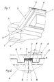
- the two kitchen utensils 1 and 2, which are close together, are connected on the cover side to the connecting element 3.
- the connecting element 3 has a U-shaped cross-sectional profile and is bent twice at the front (4; 4 '), the lower horizontal fold 4' being pushed under the device cover 5 projecting forward.
- a rear flap 6 bent upwards lies against the rear end strip 7 of the device cover.
- a correspondingly designed cover profile 8 extends over the flared tab 6 and the end strip 7.
- the connecting element 3 is thus locked in all directions without screw connection in the case of single, row and block installation.
- the two legs 9 and 9 ′ prevent lateral displacement, a forward movement is impossible due to the clamped tab 6, and the front bevels 4 and 4 ′ hold the connecting element 3 firmly on the device cover 5.
- the device cover is provided with a bead 10 along the contact side of two devices standing next to one another. Between the bead 10 and the connecting element 3 there is a seal 11 which prevents the ingress of moisture or the like.
- the pot 12 indicated in FIG. 2 is intended to illustrate this. Seamlessly embossed U-shaped openings 13 in the front area of the device cover next to the bead 10 prevent cookware from getting from one device to another.
- the device cover is trough-shaped and overflowed cookware is guided through a drain pipe 14 into the bottom shelf.
- a connecting element 15 (FIG. 4) which is identical in terms of design but deviates in size is provided for the left or right outdoor unit or the single standing unit.
- Fig. 5 indicates that two devices 1 and 2 placed at a distance from each other can be bridged by a worktop 16, which is constructed just like the connecting element. This eliminates additional connecting elements.
Landscapes
- Life Sciences & Earth Sciences (AREA)
- Sustainable Development (AREA)
- Combinations Of Kitchen Furniture (AREA)
- Sink And Installation For Waste Water (AREA)
- Connector Housings Or Holding Contact Members (AREA)
Description
- Die Erfindung betrifft eine Verbindungsvorrichtung zweier nebeneinander stehender Großküchengeräte nach dem Oberbegriff des Patentanspruches 1.
- Bei nebeneinanderstehenden Großkochgeräten sind unterschiedliche Geräteverbindungen bekannt, wie z. B. Stoßverbindungen mit Nut und Feder, Klemmleisten oder U-Rinnen. Alle diese Verbindungen sind jedoch mit Nachteilen hinsichtlich Hygiene, Reinigung, Dichtheit, Gebrauchstauglichkeit und Montage behaftet.
- Der Erfindung liegt die Aufgabe zugrunde eine Verbindungsvorrichtung zu schaffen, welche leicht zu handhaben ist und trotzdem allen Anforderungen an die Hygiene und die Gebrauchstauglichkeit genügt. Zur Lösung dieser Aufgabe werden im Patentanspruch 1 angegebenen Merkmale vorgeschlagen.
- Diese erfindungsgemäße Verbindungsvorrichtung ist ohne Schrauben einfach zu montieren und erlaubt eine raumsparende Geräteaufstellung direkt aneinander. Sie ist einwandfrei abzudichten und kann so großflächig gestaltet sein, daß sie leicht gereinigt werden kann.
- Weitere Merkmale der Erfindung sind Gegenstand der abhängigen Ansprüche 2 bis 5.
- In der Zeichnung ist die Erfindung an einem Ausführungsbeispiel dargestellt. Es zeigen:
- Fig. 1
- einen perspektivischen Ausschnitt der Geräteoberseite im Bereich der Verbindungsvorrichtung
- Fig. 2
- einen Querschnitt durch die Verbindungsvorrichtung an der Berührungsstelle zweier Großküchengeräte
- Fig. 3
- einen Längsschnitt durch die Verbindungsvorrichtung
- Fig. 4
- eine abgewandelte Form für einen seitlichen Geräteabschluß
- Fig. 5
- eine Ausführung als Arbeits- und Ausgleichsplatte
- Die beiden dicht aneinander stehenden Großküchengeräte 1 und 2 werden abdeckungsseitig mit dem Verbindungselement 3 verbunden. Das Verbindungselement 3 hat ein U-förmiges Querschnittsprofil und ist vorn zweimal abgekantet (4; 4') wobei die untere waagrechte Abkantung 4'unter die nach vorn vorstehende Geräteabdeckung 5 geschoben wird. Eine hintere nach oben abgekantete Lasche 6 legt sich an die hintere Abschlußleiste 7 der Geräteabdeckung. Ein entsprechend gestaltetes Abdeckprofil 8 greift über die aufgekantete Lasche 6 und die Abschlußleiste 7. Das Verbindungselement 3 ist somit ohne Schraubverbindung bei Einzel-, Zeilen- und auch Blockaufstellung in allen Richtungen arretiert. Die beiden Schenkel 9 und 9'verhindern ein seitliches Verschieben, eine Verschiebung nach vorne ist durch die eingeklemmte Lasche 6 unmöglich, und die vorderen Abkantungen 4 und 4' halten das Verbindungselement 3 fest auf der Geräteabdeckung 5.
- Im Bereich des Verbindungselementes 3 ist die Geräteabdeckung entlang der Berührungsseite zweier aneinander stehender Geräte mit einem Wulst 10 versehen. Zwischen dem Wulst 10 und dem Verbindungselement 3 befindet sich eine Dichtung 11, die das Eindringen von Feuchtigkeit o. dgl. verhindert. Der im Querschnitt rechteckförmige Wulst 10 einschließlich Dichtung 11 und Verbindungselement 3 sind so dimensioniert, daß die obere ebene Fläche des Verbindungselementes niveaugleich mit der Geräteabdeckung 5 ist. Es ist so ein optimales Handling durch problemloses Verschieben von Töpfen, Pfannen und Behältern gewährleistet. Der in Fig. 2 angedeutete Topf 12 soll diese verdeutlichen.
Fugenlos eingeprägte U-förmige öffnungen 13 im vorderen Bereich der Geräteabdeckung neben dem Wulst 10 verhindern, daß Kochgut von einem Gerät zum anderen gelangen kann. - Je nach Gerätetyp ist die Geräteabdeckung muldenförmig ausgebildet, und überlaufendes Kochgut wird durch ein Ablaufrohr 14 in den Bodenrost geführt.
- Für das linke bzw. rechte Außengerät oder das einzeln stehende Gerät wird ein von der Ausführung her identisches, maßlich aber abweichendes Verbindungselement 15(Fig. 4) vorgesehen.
Fig. 5 deutet an, daß zwei mit Abstand voneinander aufgestellte Geräte 1 und 2 durch eine Arbeitsplatte 16 überbrückt werden können, welche genauso wie das Verbindungselement aufgebaut ist.
Hierdurch entfallen zusätzliche Verbindungselemente.
Claims (5)
- Verbindungsvorrichtung zweier nebeneinander stehender Großküchengeräte (1;2), deren obere Geräteabdeckung (5) einerseits nach vorne über das Gerätegehäuse vorsteht und andererseits eine hintere, nach oben hochstehende Abschlußleiste (7) aufweist, dadurch gekennzeichnet,
daß die obere Geräteabdeckung entlang der Berührungsseite der beiden aneinander stehen den Geräte (1; 2) mit einem Wulst (10) versehen ist, wobei über die beiden nebeneinander liegenden Wulste (10) der beiden Geräte ein Verbindungselement (3) mit U-förmigem und dem Profil der beiden Wulste entsprechend dimensionierten Querschnitt gelemmt ist, welches an der Gerätevorderseite zweimal so abgekantet ist, daß die untere waagerechte Abkantung (4) unter die Geräteabdeckung greift, und daß eine weitere, hintere, nach oben aufgekantete Lasche (6) des Verbindungselementes (3) an der hinteren Abschlußleiste (7) anliegt, gehaltert von einem die Abschlußleiste (7) und die Lasche (6) übergreifenden Abdeckprofil (8). - Verbindungsvorrichtung nach Anspruch 1, dadurch gekennzeichnet, daß
zwischen dem Verbindungselement (3) und den Wülsten (10) eine Dichtung (11) angeordnet ist. - Verbindungsvorrichtung nach Anspruch 1 und/oder 2 dadurch gekennzeichnet, daß die Wulste (10) und das Verbindungselement (3) ein Rechteckprofil aufweisen und die obere ebene Fläche des Verbindungselementes (3) niveaugleich mit der Geräteabdeckung (5) angeordnet ist.
- Verbindungsvorrichtung nach Anspruch 1,2 oder 3 dadurch gekennzeichnet, daß das Verbindungselement (3) als Arbeitsplatte (16) ausgebildet ist.
- Verbindungsvorrichtung nach Anspruch 1, 2 oder 3 gekennzeichnet durch öffnungen (13) in der Geräteabdeckung vorn neben den Wülsten (10) zur Überlaufverhinderung von Gerät zu Gerät.
Applications Claiming Priority (2)
| Application Number | Priority Date | Filing Date | Title |
|---|---|---|---|
| DE4034250A DE4034250A1 (de) | 1990-10-27 | 1990-10-27 | Verbindungsvorrichtung fuer nebeneinander stehende grosskuechengeraete |
| DE4034250 | 1990-10-27 |
Publications (2)
| Publication Number | Publication Date |
|---|---|
| EP0483589A1 EP0483589A1 (de) | 1992-05-06 |
| EP0483589B1 true EP0483589B1 (de) | 1995-01-11 |
Family
ID=6417189
Family Applications (1)
| Application Number | Title | Priority Date | Filing Date |
|---|---|---|---|
| EP91117542A Expired - Lifetime EP0483589B1 (de) | 1990-10-27 | 1991-10-14 | Verbindungsvorrichtung für nebeneinander stehende Grossküchengeräte |
Country Status (3)
| Country | Link |
|---|---|
| EP (1) | EP0483589B1 (de) |
| AT (1) | ATE116820T1 (de) |
| DE (2) | DE4034250A1 (de) |
Families Citing this family (9)
| Publication number | Priority date | Publication date | Assignee | Title |
|---|---|---|---|---|
| NL9300962A (nl) * | 1992-07-30 | 1994-02-16 | Palux Ag | Inrichting voor de verbinding van twee naast elkaar gelegen apparaten voor de grootkeuken. |
| DE4228076C1 (en) * | 1992-08-24 | 1993-08-05 | Palux Technik Fuer Die Gastronomie Gmbh, 6990 Bad Mergentheim, De | Connecting element for two adjacent,large kitchen units etc. - is adjustable in unit butt joint and has rear hook and front screw coupling |
| ES2078160B1 (es) * | 1993-11-08 | 1998-06-16 | Fagor S Coop | Disposicion de modulos de cocinado comerciales. |
| ES2127054B1 (es) * | 1995-05-08 | 1999-12-01 | Fagor S Coop | Cocina de modulos comerciales suspendidos. |
| AT1702U1 (de) * | 1996-11-08 | 1997-10-27 | Lohberger Heiz & Kochgeraete G | Kücheneinrichtung |
| US6899404B1 (en) * | 2003-06-16 | 2005-05-31 | Ron E. King | Cabinet system |
| DE102004009606B4 (de) | 2004-02-27 | 2018-03-29 | BSH Hausgeräte GmbH | Arbeitsfeld |
| DE102011115109B4 (de) * | 2011-10-07 | 2016-09-01 | Claudia Musch | Mobile Küchenvorrichtung |
| CN109090859B (zh) * | 2018-09-14 | 2020-05-12 | 吴嘉馨 | 一种用于集成灶的无缝安装组件 |
Family Cites Families (4)
| Publication number | Priority date | Publication date | Assignee | Title |
|---|---|---|---|---|
| US2778032A (en) * | 1952-09-22 | 1957-01-22 | William J Meehan | Self-locking sink frame |
| US2789874A (en) * | 1955-05-11 | 1957-04-23 | United Metal Cabinet Corp | Counter-top brace and trim construction |
| EP0093823A1 (de) * | 1982-04-23 | 1983-11-16 | Ditta Angelo Po Grandi Impianti Spa | Einrichtungen nach dem Baukastensystem für Grossküchenanlagen |
| FR2606863B1 (fr) * | 1986-11-19 | 1990-07-13 | Rosieres Usines | Appareil de cuisson modulaire etanche |
-
1990
- 1990-10-27 DE DE4034250A patent/DE4034250A1/de not_active Withdrawn
-
1991
- 1991-10-14 AT AT91117542T patent/ATE116820T1/de not_active IP Right Cessation
- 1991-10-14 DE DE59104236T patent/DE59104236D1/de not_active Expired - Fee Related
- 1991-10-14 EP EP91117542A patent/EP0483589B1/de not_active Expired - Lifetime
Also Published As
| Publication number | Publication date |
|---|---|
| ATE116820T1 (de) | 1995-01-15 |
| DE4034250A1 (de) | 1992-04-30 |
| DE59104236D1 (de) | 1995-02-23 |
| EP0483589A1 (de) | 1992-05-06 |
Similar Documents
| Publication | Publication Date | Title |
|---|---|---|
| DE4210010C2 (de) | Kochfeldplatte | |
| DE19856538C1 (de) | Kochanordnung | |
| EP0483589B1 (de) | Verbindungsvorrichtung für nebeneinander stehende Grossküchengeräte | |
| EP3334311A1 (de) | Wandschrank, insbesondere küchen-wandschrank | |
| DE102004009606B4 (de) | Arbeitsfeld | |
| EP0754919B1 (de) | Hausgeräte-Tür, vorzugsweise Ofentür eines Backofens | |
| DE3120989C2 (de) | Küchen-Einsetzvorrichtung | |
| EP0441363B1 (de) | Einbaugerät mit Abdeckleiste | |
| EP0567779A1 (de) | Kochfeldplatte | |
| EP4434398A1 (de) | Schrankmöbel mit beleuchteter griffmulde zwischen zwei fronten | |
| DE3104910C2 (de) | Backofen | |
| DE8624136U1 (de) | Kochmulde zum Einbau in Einbauküchen | |
| DE3516546C2 (de) | Anschlußeinrichtung für eine Verkleidungsplatte an einer vertikalen Nischenrückwand im Möbelbau | |
| DE3144987C2 (de) | ||
| DE10210754B4 (de) | Schaltschrank mit einem Rahmengestell und einer Kabeleinführung in der Deckwand | |
| EP0517159B1 (de) | Anordnung einer Vorsatzplatte an einem Haushaltsgerät, insbesondere einer Geschirrspülmaschine | |
| EP0052267A1 (de) | Anordnung aus einem Küchenoberschrank und einer unter diesem sitzenden Beleuchtungsvorrichtung | |
| DE10013007C2 (de) | Schaltschrank | |
| DE9301942U1 (de) | Einbaukochfeld | |
| EP0532827A1 (de) | Duschkabine | |
| DE102013204143A1 (de) | Filtereinheit für Dunstabzugshaube und Dunstabzugshaube | |
| EP1023859A2 (de) | Tragplatte für Möbelkörper | |
| DE19517947A1 (de) | Dachpfanne aus Kunststoff oder Metall und Anbauteil für diese Dachpfanne | |
| DE102007031331A1 (de) | Kochfeld | |
| DE4306545C1 (de) | Küche mit benachbarten Funktionseinheiten |
Legal Events
| Date | Code | Title | Description |
|---|---|---|---|
| PUAI | Public reference made under article 153(3) epc to a published international application that has entered the european phase |
Free format text: ORIGINAL CODE: 0009012 |
|
| AK | Designated contracting states |
Kind code of ref document: A1 Designated state(s): AT BE CH DE FR IT LI NL SE |
|
| 17P | Request for examination filed |
Effective date: 19920527 |
|
| 17Q | First examination report despatched |
Effective date: 19940325 |
|
| GRAA | (expected) grant |
Free format text: ORIGINAL CODE: 0009210 |
|
| AK | Designated contracting states |
Kind code of ref document: B1 Designated state(s): AT BE CH DE FR IT LI NL SE |
|
| REF | Corresponds to: |
Ref document number: 116820 Country of ref document: AT Date of ref document: 19950115 Kind code of ref document: T |
|
| EAL | Se: european patent in force in sweden |
Ref document number: 91117542.0 |
|
| REF | Corresponds to: |
Ref document number: 59104236 Country of ref document: DE Date of ref document: 19950223 |
|
| ET | Fr: translation filed | ||
| ITF | It: translation for a ep patent filed | ||
| PLBE | No opposition filed within time limit |
Free format text: ORIGINAL CODE: 0009261 |
|
| STAA | Information on the status of an ep patent application or granted ep patent |
Free format text: STATUS: NO OPPOSITION FILED WITHIN TIME LIMIT |
|
| 26N | No opposition filed | ||
| PGFP | Annual fee paid to national office [announced via postgrant information from national office to epo] |
Ref country code: FR Payment date: 19991018 Year of fee payment: 9 |
|
| PGFP | Annual fee paid to national office [announced via postgrant information from national office to epo] |
Ref country code: SE Payment date: 19991021 Year of fee payment: 9 Ref country code: AT Payment date: 19991021 Year of fee payment: 9 |
|
| PGFP | Annual fee paid to national office [announced via postgrant information from national office to epo] |
Ref country code: BE Payment date: 19991022 Year of fee payment: 9 |
|
| PGFP | Annual fee paid to national office [announced via postgrant information from national office to epo] |
Ref country code: NL Payment date: 19991027 Year of fee payment: 9 |
|
| PG25 | Lapsed in a contracting state [announced via postgrant information from national office to epo] |
Ref country code: AT Free format text: LAPSE BECAUSE OF NON-PAYMENT OF DUE FEES Effective date: 20001014 |
|
| PGFP | Annual fee paid to national office [announced via postgrant information from national office to epo] |
Ref country code: CH Payment date: 20001023 Year of fee payment: 10 |
|
| PG25 | Lapsed in a contracting state [announced via postgrant information from national office to epo] |
Ref country code: SE Free format text: THE PATENT HAS BEEN ANNULLED BY A DECISION OF A NATIONAL AUTHORITY Effective date: 20001030 |
|
| PG25 | Lapsed in a contracting state [announced via postgrant information from national office to epo] |
Ref country code: BE Free format text: LAPSE BECAUSE OF NON-PAYMENT OF DUE FEES Effective date: 20001031 |
|
| PGFP | Annual fee paid to national office [announced via postgrant information from national office to epo] |
Ref country code: DE Payment date: 20001227 Year of fee payment: 10 |
|
| BERE | Be: lapsed |
Owner name: JUNO GROSSKUCHEN G.M.B.H. Effective date: 20001031 |
|
| PG25 | Lapsed in a contracting state [announced via postgrant information from national office to epo] |
Ref country code: NL Free format text: LAPSE BECAUSE OF NON-PAYMENT OF DUE FEES Effective date: 20010501 |
|
| EUG | Se: european patent has lapsed |
Ref document number: 91117542.0 |
|
| PG25 | Lapsed in a contracting state [announced via postgrant information from national office to epo] |
Ref country code: FR Free format text: LAPSE BECAUSE OF NON-PAYMENT OF DUE FEES Effective date: 20010629 |
|
| NLV4 | Nl: lapsed or anulled due to non-payment of the annual fee |
Effective date: 20010501 |
|
| REG | Reference to a national code |
Ref country code: FR Ref legal event code: ST |
|
| PG25 | Lapsed in a contracting state [announced via postgrant information from national office to epo] |
Ref country code: LI Free format text: LAPSE BECAUSE OF NON-PAYMENT OF DUE FEES Effective date: 20011031 Ref country code: CH Free format text: LAPSE BECAUSE OF NON-PAYMENT OF DUE FEES Effective date: 20011031 |
|
| REG | Reference to a national code |
Ref country code: CH Ref legal event code: PL |
|
| PG25 | Lapsed in a contracting state [announced via postgrant information from national office to epo] |
Ref country code: DE Free format text: LAPSE BECAUSE OF NON-PAYMENT OF DUE FEES Effective date: 20020702 |
|
| PG25 | Lapsed in a contracting state [announced via postgrant information from national office to epo] |
Ref country code: IT Free format text: LAPSE BECAUSE OF NON-PAYMENT OF DUE FEES;WARNING: LAPSES OF ITALIAN PATENTS WITH EFFECTIVE DATE BEFORE 2007 MAY HAVE OCCURRED AT ANY TIME BEFORE 2007. THE CORRECT EFFECTIVE DATE MAY BE DIFFERENT FROM THE ONE RECORDED. Effective date: 20051014 |