EP0483623A1 - Dispositif d'application de peinture - Google Patents
Dispositif d'application de peinture Download PDFInfo
- Publication number
- EP0483623A1 EP0483623A1 EP91117853A EP91117853A EP0483623A1 EP 0483623 A1 EP0483623 A1 EP 0483623A1 EP 91117853 A EP91117853 A EP 91117853A EP 91117853 A EP91117853 A EP 91117853A EP 0483623 A1 EP0483623 A1 EP 0483623A1
- Authority
- EP
- European Patent Office
- Prior art keywords
- shaped body
- section
- shaped
- disk
- disc
- Prior art date
- Legal status (The legal status is an assumption and is not a legal conclusion. Google has not performed a legal analysis and makes no representation as to the accuracy of the status listed.)
- Granted
Links
- 239000003973 paint Substances 0.000 title claims abstract description 16
- 239000007788 liquid Substances 0.000 claims abstract description 7
- 239000000463 material Substances 0.000 claims abstract description 5
- 230000002093 peripheral effect Effects 0.000 claims description 8
- 239000002184 metal Substances 0.000 description 2
- 238000005096 rolling process Methods 0.000 description 2
- 230000002745 absorbent Effects 0.000 description 1
- 239000002250 absorbent Substances 0.000 description 1
- 235000000396 iron Nutrition 0.000 description 1
- 238000010422 painting Methods 0.000 description 1
- 229910001220 stainless steel Inorganic materials 0.000 description 1
- 239000010935 stainless steel Substances 0.000 description 1
- 239000004753 textile Substances 0.000 description 1
- 230000007704 transition Effects 0.000 description 1
Images

Classifications
-
- B—PERFORMING OPERATIONS; TRANSPORTING
- B05—SPRAYING OR ATOMISING IN GENERAL; APPLYING FLUENT MATERIALS TO SURFACES, IN GENERAL
- B05C—APPARATUS FOR APPLYING FLUENT MATERIALS TO SURFACES, IN GENERAL
- B05C17/00—Hand tools or apparatus using hand held tools, for applying liquids or other fluent materials to, for spreading applied liquids or other fluent materials on, or for partially removing applied liquids or other fluent materials from, surfaces
- B05C17/02—Rollers ; Hand tools comprising coating rollers or coating endless belts
- B05C17/0212—Rollers ; Hand tools comprising coating rollers or coating endless belts the coating surface of the roller being a body of revolution generated by a generatrix that is not a straight line parallel to the roller axis, e.g. for allowing coating of non planar surfaces
-
- A—HUMAN NECESSITIES
- A46—BRUSHWARE
- A46B—BRUSHES
- A46B11/00—Brushes with reservoir or other means for applying substances, e.g. paints, pastes, water
- A46B11/06—Brushes with reservoir or other means for applying substances, e.g. paints, pastes, water connected to supply pipe or to other external supply means
- A46B11/063—Brushes with reservoir or other means for applying substances, e.g. paints, pastes, water connected to supply pipe or to other external supply means by means of a supply pipe
-
- A—HUMAN NECESSITIES
- A46—BRUSHWARE
- A46B—BRUSHES
- A46B7/00—Bristle carriers arranged in the brush body
- A46B7/06—Bristle carriers arranged in the brush body movably during use, i.e. the normal brushing action causing movement
- A46B7/10—Bristle carriers arranged in the brush body movably during use, i.e. the normal brushing action causing movement as a rotating cylinder
-
- B—PERFORMING OPERATIONS; TRANSPORTING
- B05—SPRAYING OR ATOMISING IN GENERAL; APPLYING FLUENT MATERIALS TO SURFACES, IN GENERAL
- B05C—APPARATUS FOR APPLYING FLUENT MATERIALS TO SURFACES, IN GENERAL
- B05C17/00—Hand tools or apparatus using hand held tools, for applying liquids or other fluent materials to, for spreading applied liquids or other fluent materials on, or for partially removing applied liquids or other fluent materials from, surfaces
- B05C17/02—Rollers ; Hand tools comprising coating rollers or coating endless belts
- B05C17/0227—Rollers ; Hand tools comprising coating rollers or coating endless belts comprising several coating rollers
-
- B—PERFORMING OPERATIONS; TRANSPORTING
- B05—SPRAYING OR ATOMISING IN GENERAL; APPLYING FLUENT MATERIALS TO SURFACES, IN GENERAL
- B05C—APPARATUS FOR APPLYING FLUENT MATERIALS TO SURFACES, IN GENERAL
- B05C17/00—Hand tools or apparatus using hand held tools, for applying liquids or other fluent materials to, for spreading applied liquids or other fluent materials on, or for partially removing applied liquids or other fluent materials from, surfaces
- B05C17/02—Rollers ; Hand tools comprising coating rollers or coating endless belts
- B05C17/0227—Rollers ; Hand tools comprising coating rollers or coating endless belts comprising several coating rollers
- B05C17/023—Rollers ; Hand tools comprising coating rollers or coating endless belts comprising several coating rollers all of them having parallel axises
- B05C17/0232—Rollers ; Hand tools comprising coating rollers or coating endless belts comprising several coating rollers all of them having parallel axises all of them having the same axis
-
- B—PERFORMING OPERATIONS; TRANSPORTING
- B05—SPRAYING OR ATOMISING IN GENERAL; APPLYING FLUENT MATERIALS TO SURFACES, IN GENERAL
- B05C—APPARATUS FOR APPLYING FLUENT MATERIALS TO SURFACES, IN GENERAL
- B05C17/00—Hand tools or apparatus using hand held tools, for applying liquids or other fluent materials to, for spreading applied liquids or other fluent materials on, or for partially removing applied liquids or other fluent materials from, surfaces
- B05C17/02—Rollers ; Hand tools comprising coating rollers or coating endless belts
- B05C17/03—Rollers ; Hand tools comprising coating rollers or coating endless belts with feed system for supplying material from an external source or with a reservoir or container for liquid or other fluent material located in or on the hand tool outside the coating roller
- B05C17/0308—Rollers ; Hand tools comprising coating rollers or coating endless belts with feed system for supplying material from an external source or with a reservoir or container for liquid or other fluent material located in or on the hand tool outside the coating roller the liquid being supplied to the inside of the coating roller
Definitions
- the invention relates to a device for applying paint.
- Corners can generally only be painted with a brush, which is very time-consuming. However, there are a large number of corners in the most diverse places of a building. So z. B. on a sheet metal roof, the upstanding folds that connect the individual sheets can be painted with the brush in hours or even days of work. Furthermore, it is often necessary to paint pipes or edges.
- a lattice mast or girder consists of a variety of angle irons and other angular profiles that can only be painstakingly painted with a brush.
- the object of the invention is to provide a device with which the paint can also be applied quickly and cleanly to such places or objects which are difficult to paint themselves.
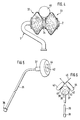
- the device has a disk-shaped body 1 which is rotatably mounted on the end section 2 of a tube 3.
- the disc-shaped body 1 has an annular peripheral section 4, which is connected via a plate-shaped central part 5 to a hub 6, through which the end section 2 of the tube 3 is pushed.
- the tube 3 has at the end section 2, on which the hub 6 is rotatably mounted, on both sides of the plate-shaped central part 5 radial bores 7 to 10.
- the hub 6 is provided on both sides of the plate-shaped central part 5 with radial bores 11 to 14.
- the radial bores 7 to 10 in the tube 3 and Radial bores 11 to 14 in the hub 6 are arranged so that they can be brought into alignment when the disk-shaped body 1 rotates.
- the radial bores 11 to 14 in the hub 6 open directly next to the plate-shaped central part 5. Furthermore, 5 radial bores 15 are provided in the annular peripheral section 4 on both sides of the plate-shaped central part, which extend from the inside directly next to the plate-shaped central part 4 to the outer circumference. The number of radial bores 15 in the peripheral section 4 is greater than that of the radial bores 11 to 14 in the hub 6.
- a sleeve 16, 17 is inserted on each end of the hub 6, each of which is provided with a ring section 18, 19 which is arranged at a distance from the plate-shaped central part 5.
- annular strip 20 made of a porous, absorbent material which is permeable to liquid color, for example a textile material which is provided with a skin 21 on the outside.
- a cord 22, 23, a rubber band or the like is pulled through its two longitudinal edges.
- the longitudinal edges of the strip 20 lie firmly against the sleeve 16, 17, specifically on the side of the ring sections 18 facing the plate-shaped central part 5, 19.
- the ring sections 18, 19 thus prevent the longitudinal edges of the strip 20 from sliding off the hub 6 and the strip 20 thus becoming detached from the device.
- the annular circumferential section 4 is formed from two conical ring sections 24, 25 which are connected to one another at their base.
- the peripheral section 4 has a wedge-shaped cross section that tapers outwards.
- the circumferential section can, for example, also have a circumferential crowned cross section.
- the end section 2 of the tube 3 is closed by a stopper, for example a screw 26.
- a washer 27 is also secured by the screw 26.
- the hub 6 is axially secured by the washer 27 or a disk 28 at the other end of the hub 6.
- an S-shaped transition section 29 which leads to an end section 30 which extends perpendicular to the end section 2.
- the section 30 is provided with a union nut 31, with which the tube 3 can be connected to a line, not shown, which leads to a color printing device.
- a straight extension tube can be provided between this line and section 30, which also serves as a support rod.
- the liquid ink supplied by the color printing device via the tube 3 flows via the radial bores 7 to 10 in the tube 3 and the radial bores 11 to 14 in FIG Hub 6 on both sides of the plate-shaped central part 5, from where it flows through the centrifugal force when rotating the disc-shaped body 1 into the radial bores 15 in the peripheral section 4 and thus to the outer periphery of the peripheral section 4, where it is sucked up by the strip 20 or skin 21 becomes.
- Part of the paint flows laterally from the plate-shaped central part 5 to the strip 20 or skin 21. In this way, the skin 21 is uniformly soaked with paint, which is then released by moving along and thus rolling the disk-shaped body 1 along the corner to be painted .
- the tube 3 can be a stainless steel tube, for example.
- the disc-shaped body 1 preferably consists of a plastic part. Between the tube 3 and the hub 6, a sleeve with corresponding bores can be provided for better mounting of the disk-shaped body 1.
- the embodiment according to FIG. 4 differs from that according to FIGS. 1 to 3 essentially only in that two disk-shaped bodies 32, 33 are arranged side by side on the correspondingly longer end section 2 of the tube 3. Both disk-shaped bodies 32, 33 are designed in the same way as the disk-shaped body 1 according to FIGS. 1 to 3, except that they are provided with radial bores only on their inside, that is to say on the sides facing one another.
- the device according to FIG. 4 is primarily used for painting cylindrical or partially cylindrical objects, e.g. B. the tube 45, or corrugated roofs, so that the mutually facing outer sides of the disc-shaped body 32, 33 are not required for the application of paint.
- the disk-shaped bodies 32, 33 can be rotated independently of one another and are separated from one another by a washer 34.
- 5 and 6 has a main pipeline 35 which is provided at one end with a union nut 36 in order to connect an extension pipe, not shown.
- a disk-shaped distributor piece 37 is provided, which has three radial bores 38, 39, 40 converging in the middle (FIG. 6). The other end of the main pipeline 5 is inserted into the radial bore 38.
- the main pipeline 35 is curved at the end facing the disk-shaped distributor piece 37, with respect to the distributor piece 37, from the radial slightly in the axial direction, for example by approximately 45 °, as can be seen from FIG. 5.
- the pipe sockets 41, 42 and the disk-shaped bodies 43, 44 are designed in the same way as the disk-shaped body 1 on the pipe end section 2 according to FIGS. 1 to 3.
- the paint can be delivered to an edge 45 to be painted by moving along and thus rolling the disc-shaped body 43, 44, as indicated in FIG. 6.
- the disc-shaped bodies 43, 44 are arranged so that they touch, but e.g. a metal tape to be painted fits between them. I.e. the adjacent circumferential sections of the disk-shaped bodies 43, 44 are at a distance of the order of one centimeter.
Landscapes
- Engineering & Computer Science (AREA)
- Mechanical Engineering (AREA)
- Coating Apparatus (AREA)
Priority Applications (1)
| Application Number | Priority Date | Filing Date | Title |
|---|---|---|---|
| AT91117853T ATE99194T1 (de) | 1990-10-22 | 1991-10-18 | Farbauftragegeraet. |
Applications Claiming Priority (4)
| Application Number | Priority Date | Filing Date | Title |
|---|---|---|---|
| DE9014627U | 1990-10-22 | ||
| DE9014627U DE9014627U1 (de) | 1990-10-22 | 1990-10-22 | Farbauftragegerät |
| DE9102491U DE9102491U1 (de) | 1991-03-02 | 1991-03-02 | Farbauftragegerät |
| DE9102491U | 1991-03-02 |
Publications (2)
| Publication Number | Publication Date |
|---|---|
| EP0483623A1 true EP0483623A1 (fr) | 1992-05-06 |
| EP0483623B1 EP0483623B1 (fr) | 1993-12-29 |
Family
ID=25957338
Family Applications (1)
| Application Number | Title | Priority Date | Filing Date |
|---|---|---|---|
| EP91117853A Expired - Lifetime EP0483623B1 (fr) | 1990-10-22 | 1991-10-18 | Dispositif d'application de peinture |
Country Status (2)
| Country | Link |
|---|---|
| EP (1) | EP0483623B1 (fr) |
| DE (1) | DE59100778D1 (fr) |
Citations (4)
| Publication number | Priority date | Publication date | Assignee | Title |
|---|---|---|---|---|
| US2722029A (en) * | 1948-03-22 | 1955-11-01 | Charles H Barnes | Paint roller applicator |
| US2929089A (en) * | 1958-10-06 | 1960-03-22 | Warren L Nall | Paint applicator for corners |
| CH405998A (de) * | 1963-02-20 | 1966-01-15 | Maag Richard | Einrichtung zum Auftragen von Malerfarbe |
| GB2172820A (en) * | 1985-03-14 | 1986-10-01 | Alan David France | Paint roller |
Family Cites Families (1)
| Publication number | Priority date | Publication date | Assignee | Title |
|---|---|---|---|---|
| US2882541A (en) * | 1956-02-06 | 1959-04-21 | Southwestern Dev Company | Roller paint applicator |
-
1991
- 1991-10-18 DE DE91117853T patent/DE59100778D1/de not_active Expired - Fee Related
- 1991-10-18 EP EP91117853A patent/EP0483623B1/fr not_active Expired - Lifetime
Patent Citations (4)
| Publication number | Priority date | Publication date | Assignee | Title |
|---|---|---|---|---|
| US2722029A (en) * | 1948-03-22 | 1955-11-01 | Charles H Barnes | Paint roller applicator |
| US2929089A (en) * | 1958-10-06 | 1960-03-22 | Warren L Nall | Paint applicator for corners |
| CH405998A (de) * | 1963-02-20 | 1966-01-15 | Maag Richard | Einrichtung zum Auftragen von Malerfarbe |
| GB2172820A (en) * | 1985-03-14 | 1986-10-01 | Alan David France | Paint roller |
Also Published As
| Publication number | Publication date |
|---|---|
| EP0483623B1 (fr) | 1993-12-29 |
| DE59100778D1 (de) | 1994-02-10 |
Similar Documents
| Publication | Publication Date | Title |
|---|---|---|
| DE2260790C2 (de) | Schneidkopf für eine Vorrichtung zum Schneiden von Pflanzen | |
| EP0603114B1 (fr) | Dispositif de serrage | |
| DE1228138B (de) | Luftrakelvorrichtung | |
| DE2120669A1 (de) | Schleifblatt | |
| DE2213779A1 (de) | Vorrichtung für die Demontage und Montage von Reifen | |
| CH683839A5 (de) | Handgehaltene Abdeckvorrichtung. | |
| CH624591A5 (fr) | ||
| DE4108489C2 (de) | Verfahren und Vorrichtung zum Aufbringen einer gleichförmigen Klebstoffschicht auf einen harzbeschichteten Dorn | |
| EP0205776B1 (fr) | Equipement pour le centrage de tubes devant être soudés entre eux | |
| DE2009509C3 (de) | Maschine zur kontinuierlichen Herstellung von Bewehrungskörben für Pfähle, Masten o.dgl. aus Stahlbeton | |
| DE2119325B2 (de) | Formschluessige kupplung zur uebertragung grosser drehmomente | |
| EP0483623B1 (fr) | Dispositif d'application de peinture | |
| DE2743017B2 (de) | Kühlmittelbrause für Umfangsschleifscheiben | |
| DE3337878A1 (de) | Auftragsgeraet fuer klebstoff | |
| DE2532855A1 (de) | Vorrichtung zum beschichten von leisten | |
| EP0995499A1 (fr) | Dispositif d'application et/ou de répartition de matières liquides ou pâteuses pour le revêtement de surfaces | |
| EP0095021B1 (fr) | Connecteur pour panneaux | |
| DE2755812C3 (de) | Vorrichtung zur Oberflächenbehandlung von Papier | |
| DE9014627U1 (de) | Farbauftragegerät | |
| DE2503664A1 (de) | Anrollkopf fuer flaschenstopfen- schutzkapseln | |
| DE9102491U1 (de) | Farbauftragegerät | |
| EP0498323A2 (fr) | Dispositif de connexion étanche pour embouts de tuyaux lisses | |
| DE3712522A1 (de) | Einrichtung zum falten und festhalten der laschen eines faltschachtelzuschnittes | |
| DE2137118C3 (de) | Anordnung zur Befestigung von Düsen oder Düsenträgern an einem Leitungsrohr | |
| DE3320904A1 (de) | Buerste zum reinigen von behaeltern und verwendung derselben |
Legal Events
| Date | Code | Title | Description |
|---|---|---|---|
| PUAI | Public reference made under article 153(3) epc to a published international application that has entered the european phase |
Free format text: ORIGINAL CODE: 0009012 |
|
| AK | Designated contracting states |
Kind code of ref document: A1 Designated state(s): AT DE FR GB NL |
|
| 17P | Request for examination filed |
Effective date: 19920917 |
|
| 17Q | First examination report despatched |
Effective date: 19921209 |
|
| GRAA | (expected) grant |
Free format text: ORIGINAL CODE: 0009210 |
|
| AK | Designated contracting states |
Kind code of ref document: B1 Designated state(s): AT DE FR GB NL |
|
| PG25 | Lapsed in a contracting state [announced via postgrant information from national office to epo] |
Ref country code: NL Effective date: 19931229 Ref country code: GB Effective date: 19931229 |
|
| REF | Corresponds to: |
Ref document number: 99194 Country of ref document: AT Date of ref document: 19940115 Kind code of ref document: T |
|
| REF | Corresponds to: |
Ref document number: 59100778 Country of ref document: DE Date of ref document: 19940210 |
|
| ET | Fr: translation filed | ||
| NLV1 | Nl: lapsed or annulled due to failure to fulfill the requirements of art. 29p and 29m of the patents act | ||
| GBV | Gb: ep patent (uk) treated as always having been void in accordance with gb section 77(7)/1977 [no translation filed] |
Effective date: 19931229 |
|
| PGFP | Annual fee paid to national office [announced via postgrant information from national office to epo] |
Ref country code: FR Payment date: 19940930 Year of fee payment: 4 |
|
| PGFP | Annual fee paid to national office [announced via postgrant information from national office to epo] |
Ref country code: AT Payment date: 19941025 Year of fee payment: 4 |
|
| PLBE | No opposition filed within time limit |
Free format text: ORIGINAL CODE: 0009261 |
|
| STAA | Information on the status of an ep patent application or granted ep patent |
Free format text: STATUS: NO OPPOSITION FILED WITHIN TIME LIMIT |
|
| 26N | No opposition filed | ||
| PG25 | Lapsed in a contracting state [announced via postgrant information from national office to epo] |
Ref country code: AT Effective date: 19951018 |
|
| PG25 | Lapsed in a contracting state [announced via postgrant information from national office to epo] |
Ref country code: FR Effective date: 19960628 |
|
| REG | Reference to a national code |
Ref country code: FR Ref legal event code: ST |
|
| PGFP | Annual fee paid to national office [announced via postgrant information from national office to epo] |
Ref country code: DE Payment date: 20031223 Year of fee payment: 13 |
|
| PG25 | Lapsed in a contracting state [announced via postgrant information from national office to epo] |
Ref country code: DE Free format text: LAPSE BECAUSE OF NON-PAYMENT OF DUE FEES Effective date: 20050503 |