EP0483625A1 - Panneau latéral d'une caisse de camion ou d'une remorque - Google Patents
Panneau latéral d'une caisse de camion ou d'une remorque Download PDFInfo
- Publication number
- EP0483625A1 EP0483625A1 EP91117879A EP91117879A EP0483625A1 EP 0483625 A1 EP0483625 A1 EP 0483625A1 EP 91117879 A EP91117879 A EP 91117879A EP 91117879 A EP91117879 A EP 91117879A EP 0483625 A1 EP0483625 A1 EP 0483625A1
- Authority
- EP
- European Patent Office
- Prior art keywords
- side wall
- sidewall
- parts
- wall part
- box body
- Prior art date
- Legal status (The legal status is an assumption and is not a legal conclusion. Google has not performed a legal analysis and makes no representation as to the accuracy of the status listed.)
- Withdrawn
Links
- 238000006073 displacement reaction Methods 0.000 claims description 4
- 238000000034 method Methods 0.000 description 6
- 238000010276 construction Methods 0.000 description 1
- 230000005484 gravity Effects 0.000 description 1
- 238000012986 modification Methods 0.000 description 1
- 230000004048 modification Effects 0.000 description 1
- 230000000087 stabilizing effect Effects 0.000 description 1
Images



Classifications
-
- B—PERFORMING OPERATIONS; TRANSPORTING
- B60—VEHICLES IN GENERAL
- B60J—WINDOWS, WINDSCREENS, NON-FIXED ROOFS, DOORS, OR SIMILAR DEVICES FOR VEHICLES; REMOVABLE EXTERNAL PROTECTIVE COVERINGS SPECIALLY ADAPTED FOR VEHICLES
- B60J5/00—Doors
- B60J5/04—Doors arranged at the vehicle sides
- B60J5/0497—Doors arranged at the vehicle sides for load transporting vehicles or public transport, e.g. lorries, trucks, buses
- B60J5/0498—Doors arranged at the vehicle sides for load transporting vehicles or public transport, e.g. lorries, trucks, buses with rigid panels pivoting about a horizontal axis
Definitions
- the invention relates to a side wall of a box body of a truck or trailer, which is horizontally divided into articulated side wall parts and can be opened by angling the side wall parts against each other from the side wall level upwards until the lower side wall part is folded up to the upper one.
- the lower side wall part folds under the upper side wall part; the two side wall parts project together as a canopy.
- the disadvantage is that they can hinder the loading of the car with a forklift or the like.
- Another disadvantage is that the forces involved are very large, so that there is often damage to the joints of the side wall parts, but above all to a deflection of the up to 13 m long side wall parts held only at their ends by the drive device. This is already disturbing during the opening process.
- the object of the invention is to propose a side wall of the type mentioned, which is space-saving and stable and can be opened in a simple manner.
- the side wall is divided into at least four such side wall parts and the hinge axis between the second and the third side wall part is held from above by two lateral vertical guides and projections of the side wall engaging in these approximately in the side wall plane and the drive device at least partially engages in or below the hinge axis mentioned on the side wall, such that the side wall parts are angled in an alternating direction and folded together.
- the new construction is even more advantageous in the further embodiment that the uppermost side wall part on its upper long side is firmly connected at approximately a right angle to the associated long side of a roof section of the box body, which is articulated with its other long side upwards on the box body. Then there is a vertical end position of the side wall parts and in this way stability in the folded state in which the angles stabilizing during the opening process have disappeared again. Furthermore, the side wall parts protrude upwards and not to the side, so that they do not interfere with loading and unloading.
- the reduced width of the side wall parts requires not a lot of space upwards either, and the same when opening out to the side.
- locking elements are arranged on vertical spars of the box structure, which can be brought into engagement with associated locking elements arranged on lower side wall parts by displacement in the vertical direction, and the drive device is designed such that it only follows these lower side wall parts when the side wall is opened a mere shift upwards out of the side wall level, angled against each other and when closing the side wall it can be placed in the side wall level shortly before the closed position.
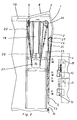
- a side wall of a box structure consists of four side wall parts 1, 2, 4 and 5 (FIG. 1).
- the upper side wall part 1 is firmly connected at its upper longitudinal edge 7 at right angles to the associated long side of a roof section 8, which is articulated with the other long side 9 so that it can pivot upwards on the box structure 10.
- the side wall part 2 is articulated at its upper longitudinal edge to the lower longitudinal edge of the upper side wall part 1 such that the side wall part 2 can be folded inwards.
- the side wall part 4 is connected at its upper longitudinal edge in such an articulated manner to the lower longitudinal edge of the side wall part 2 that the side wall part 4 can be folded out onto the side wall part 2.
- the side wall part 5 is finally connected at its upper longitudinal edge in such an articulated manner to the side wall part 4 that the side wall part 5 can be folded inwards onto the side wall part 4.
- two guides 33 are attached to it, in which two rollers 23 arranged as projections on the side wall part 2 slide.
- the rollers 23 are close to the hinge axis 43 between the side wall parts 2 and 4.
- locking elements 12 are arranged on the side wall parts 4 and 5, which interact with associated locking elements 11 arranged on vertical bars 16 of the box structure 10.
- the locking elements 11 and 12 are engaged or disengaged by a displacement of the side wall sections in the vertical direction.
- one-armed levers are pivotably arranged as guide parts 15 on the side wall sections.
- the guide parts 15 pivot due to the force of gravity when folding the side wall sections down and towards the side wall level and thus get into the guide structure assigned to the box structure when the side wall is closed, so that the side wall parts are guided securely into the closed position.
- the guide parts 15 are mounted as foldable levers on bars 16 of the box structure 10. They are expanded or collapsed via bolts 17 moved through the side wall parts via an associated cam guide 18.
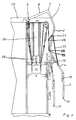
- the drive device has a hydraulically or pneumatically operable pressure cylinder 19 with a piston rod 20.
- the free end of the piston rod 20 carries a deflection roller 21, over which a rope 22 is guided.
- the cable 22 is connected at one end to the box structure 10, guided over the deflection roller 21 and over a further deflection roller 24 arranged in the upper corner of the box structure 10 and fastened at its other end to the lower longitudinal edge of the side wall part 2.
- a cable 25 is provided, which is fastened at one end 26 to the box structure 10 and at the other end to the side wall part 4.
- the cable 25 is also guided over a deflection roller 27 on the side wall part 2.
- the length and the fastening of the cable 25 and the arrangement of the deflection roller 27 are chosen such that the cable only becomes effective in one position, as shown in FIG. 2.
- the lower side wall parts 4 and 5 are first shifted in a vertical direction, so that the locking elements 11 and 12 disengage.
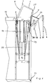
- a pressure cylinder 19 with its piston rod 20 is arranged between the box structure 10 and the roof section 8.
- the roof section 8 is pivoted upward into the position shown in FIG. 7.
- the cable 25 is attached at one end to the side wall part 4.
- the cable 25 is on a deflection roller 27 (Fig. 6) on the side wall part 2, another deflection roller 28 on the upper Side wall part 1 connected roof section 8 and a further deflection roller 30 arranged on the upper, front edge of the box structure 10 on a pivotable lever 29.
- the other end of the cable 25 is attached to the upper side wall part 1.
- the lever 29 pivots from the position shown in FIG. 5 into the position shown in FIGS. 6 and 7. This pivoting movement ensures that the cable 25 is only effective after a vertical displacement of the side wall sections, so that the locking elements disengage.
- the deflection roller 30 is fixedly arranged, so that the cable 25 is tightened faster.
- the deflection roller 27 is moved to the hinge axis between the side wall parts 1 and 2, the end of the cable 25 to the hinge axis between the side wall parts 4 and 5.
Landscapes
- Engineering & Computer Science (AREA)
- Mechanical Engineering (AREA)
- Loading Or Unloading Of Vehicles (AREA)
- Body Structure For Vehicles (AREA)
Applications Claiming Priority (2)
| Application Number | Priority Date | Filing Date | Title |
|---|---|---|---|
| DE4034270 | 1990-10-27 | ||
| DE19904034270 DE4034270A1 (de) | 1990-10-27 | 1990-10-27 | Seitenwand fuer den kastenaufbau eines lastkraftwagens bzw. eines anhaengers |
Publications (1)
| Publication Number | Publication Date |
|---|---|
| EP0483625A1 true EP0483625A1 (fr) | 1992-05-06 |
Family
ID=6417195
Family Applications (1)
| Application Number | Title | Priority Date | Filing Date |
|---|---|---|---|
| EP91117879A Withdrawn EP0483625A1 (fr) | 1990-10-27 | 1991-10-19 | Panneau latéral d'une caisse de camion ou d'une remorque |
Country Status (2)
| Country | Link |
|---|---|
| EP (1) | EP0483625A1 (fr) |
| DE (1) | DE4034270A1 (fr) |
Cited By (1)
| Publication number | Priority date | Publication date | Assignee | Title |
|---|---|---|---|---|
| EP0610580A1 (fr) * | 1993-02-11 | 1994-08-17 | Claas Saulgau Gmbh | Paroi arrière pour un chariot chargeur |
Families Citing this family (5)
| Publication number | Priority date | Publication date | Assignee | Title |
|---|---|---|---|---|
| DE4229503C2 (de) * | 1992-09-04 | 1995-08-17 | Karosseriebau Duenschede Gmbh | Lastkraftwagen-Kastenaufbau mit Seitenwand-Öffnungsmechanik |
| DE4237410C2 (de) * | 1992-11-05 | 1996-02-29 | Europ Semi Remorques | Pritschenaufbau für LKW-Wechselbehälter und Festaufbauten |
| DE4237473A1 (de) * | 1992-11-06 | 1994-05-11 | Robert Orten Gmbh & Co | Verschlußvorrichtung |
| DE102011004103A1 (de) | 2011-02-15 | 2012-08-16 | Schaeffler Technologies Gmbh & Co. Kg | Mehrreihiges Wälzlager |
| EP3473422B1 (fr) * | 2017-10-23 | 2022-11-09 | Wincor Nixdorf International GmbH | Système compacteur et procédé de montage et de maintien d'un système compacteur |
Citations (3)
| Publication number | Priority date | Publication date | Assignee | Title |
|---|---|---|---|---|
| DE7332808U (de) * | 1974-01-31 | Vereinigte Flugtechnische Werke Fokker Gmbh | Ladetüranordnung an kastenförmigen Aufbauten, insbesondere Aufbauten von Kühlfahrzeugen | |
| DE7416667U (de) * | 1974-09-19 | Brandt W | Kastenförmige Laderaum verkleidung für Lastkraftwagen | |
| DE8412239U1 (de) * | 1984-04-18 | 1984-08-30 | Macar Oldenzaal BV, Oldenzaal | Karosserieaufbau fuer lastkraftwagen oder anhaenger od. dgl. |
-
1990
- 1990-10-27 DE DE19904034270 patent/DE4034270A1/de not_active Withdrawn
-
1991
- 1991-10-19 EP EP91117879A patent/EP0483625A1/fr not_active Withdrawn
Patent Citations (3)
| Publication number | Priority date | Publication date | Assignee | Title |
|---|---|---|---|---|
| DE7332808U (de) * | 1974-01-31 | Vereinigte Flugtechnische Werke Fokker Gmbh | Ladetüranordnung an kastenförmigen Aufbauten, insbesondere Aufbauten von Kühlfahrzeugen | |
| DE7416667U (de) * | 1974-09-19 | Brandt W | Kastenförmige Laderaum verkleidung für Lastkraftwagen | |
| DE8412239U1 (de) * | 1984-04-18 | 1984-08-30 | Macar Oldenzaal BV, Oldenzaal | Karosserieaufbau fuer lastkraftwagen oder anhaenger od. dgl. |
Cited By (1)
| Publication number | Priority date | Publication date | Assignee | Title |
|---|---|---|---|---|
| EP0610580A1 (fr) * | 1993-02-11 | 1994-08-17 | Claas Saulgau Gmbh | Paroi arrière pour un chariot chargeur |
Also Published As
| Publication number | Publication date |
|---|---|
| DE4034270A1 (de) | 1992-01-16 |
Similar Documents
| Publication | Publication Date | Title |
|---|---|---|
| DE102017113053B4 (de) | Großladungsträger mit Schwenkklappe | |
| EP0101475B1 (fr) | Caisse, en particulier pour camion, ayant une paroi laterale rabattable | |
| DE4413444A1 (de) | Laderampe für Kraftfahrzeuge | |
| DE202013008638U1 (de) | Schiebeplane für einen Nutzfahrzeugaufbau | |
| EP0483625A1 (fr) | Panneau latéral d'une caisse de camion ou d'une remorque | |
| DE1683704B2 (de) | Vorrichtung zur Betätigung und Abdichtung von schiebbaren oder kipp- und/oder schwenkbaren Flügeln von Fenstern oder Türen | |
| DE2755056A1 (de) | Lukenabdeckung mit mindestens drei unmittelbar faltbar aneinander angelenkten deckeln | |
| DE1580650B2 (de) | Verschlussvorrichtung fuer klappbare bordwaende von ladebruecken an lastkraftwagen o.dgl. | |
| DE3412995C2 (de) | Spannrahmen für Kettenkratzförderer, insbesondere für Untertagebetriebe | |
| DE20215675U1 (de) | Nutzfahrzeug mit längs verschiebbarem Hubdach | |
| DE212023000404U1 (de) | Faltcontainer für den Fahrzeugtransport | |
| DE3220859C2 (de) | Langgut-Container | |
| DE2225883C3 (de) | Vertikalschiebefenster | |
| DE3919349C2 (fr) | ||
| DE6602991U (de) | Lastdrueckgeraet, insbesondere fuer hubkarren | |
| DE8420338U1 (de) | Schiebeverdeck-Planengestell | |
| DE945435C (de) | Zusammenlegbarer, rechteckiger Versandbehaelter | |
| DE102016106320B4 (de) | Planenaufbau | |
| DE1284314B (de) | Kastenverschluss, insbesondere fuer klappbare Bordwaende an Strassenfahrzeugen | |
| DE3901797C1 (fr) | ||
| DE2218866A1 (de) | Vorrichtung zum Wegklappen der hinteren Bordwand an der Pritsche eines Kipperfahrzeuges | |
| DE2212070B2 (de) | Faltlukendeckelanordnung | |
| DE7723817U1 (de) | Fahrzeugdach | |
| DE202011002551U1 (de) | Transport- und Lagerbehälter | |
| DE1219822B (de) | Lukenabdeckung fuer Schiffe, insbesondere Binnenschiffe und Schuten |
Legal Events
| Date | Code | Title | Description |
|---|---|---|---|
| PUAI | Public reference made under article 153(3) epc to a published international application that has entered the european phase |
Free format text: ORIGINAL CODE: 0009012 |
|
| AK | Designated contracting states |
Kind code of ref document: A1 Designated state(s): AT BE CH DE ES FR GB IT LI LU NL |
|
| 17P | Request for examination filed |
Effective date: 19920902 |
|
| 17Q | First examination report despatched |
Effective date: 19930728 |
|
| STAA | Information on the status of an ep patent application or granted ep patent |
Free format text: STATUS: THE APPLICATION IS DEEMED TO BE WITHDRAWN |
|
| 18D | Application deemed to be withdrawn |
Effective date: 19931123 |