EP0483626B1 - Aussenleuchte - Google Patents
Aussenleuchte Download PDFInfo
- Publication number
- EP0483626B1 EP0483626B1 EP91117881A EP91117881A EP0483626B1 EP 0483626 B1 EP0483626 B1 EP 0483626B1 EP 91117881 A EP91117881 A EP 91117881A EP 91117881 A EP91117881 A EP 91117881A EP 0483626 B1 EP0483626 B1 EP 0483626B1
- Authority
- EP
- European Patent Office
- Prior art keywords
- trough
- screen
- housing
- parts
- electrical block
- Prior art date
- Legal status (The legal status is an assumption and is not a legal conclusion. Google has not performed a legal analysis and makes no representation as to the accuracy of the status listed.)
- Expired - Lifetime
Links
Images
Classifications
-
- F—MECHANICAL ENGINEERING; LIGHTING; HEATING; WEAPONS; BLASTING
- F21—LIGHTING
- F21V—FUNCTIONAL FEATURES OR DETAILS OF LIGHTING DEVICES OR SYSTEMS THEREOF; STRUCTURAL COMBINATIONS OF LIGHTING DEVICES WITH OTHER ARTICLES, NOT OTHERWISE PROVIDED FOR
- F21V3/00—Globes; Bowls; Cover glasses
-
- F—MECHANICAL ENGINEERING; LIGHTING; HEATING; WEAPONS; BLASTING
- F21—LIGHTING
- F21S—NON-PORTABLE LIGHTING DEVICES; SYSTEMS THEREOF; VEHICLE LIGHTING DEVICES SPECIALLY ADAPTED FOR VEHICLE EXTERIORS
- F21S8/00—Lighting devices intended for fixed installation
- F21S8/08—Lighting devices intended for fixed installation with a standard
- F21S8/085—Lighting devices intended for fixed installation with a standard of high-built type, e.g. street light
- F21S8/086—Lighting devices intended for fixed installation with a standard of high-built type, e.g. street light with lighting device attached sideways of the standard, e.g. for roads and highways
-
- F—MECHANICAL ENGINEERING; LIGHTING; HEATING; WEAPONS; BLASTING
- F21—LIGHTING
- F21V—FUNCTIONAL FEATURES OR DETAILS OF LIGHTING DEVICES OR SYSTEMS THEREOF; STRUCTURAL COMBINATIONS OF LIGHTING DEVICES WITH OTHER ARTICLES, NOT OTHERWISE PROVIDED FOR
- F21V15/00—Protecting lighting devices from damage
- F21V15/01—Housings, e.g. material or assembling of housing parts
Definitions
- the invention relates to an outdoor light, which is composed of a plurality of components according to a modular system and has a multi-part, partially translucent, rotationally symmetrical housing around a central electrical block with a lamp holder, the housing designed as a two-part translucent trough being provided with an annular screen.
- Such an outdoor lamp composed of alternative parts according to the modular principle to achieve different types of lamps is known (DE-U-88 05 030).
- multi-part hoods and cover troughs are provided as housing parts, which are firmly assigned to a profiled ring body from both sides.
- a variety of holding and locking elements for the housing parts and for mast attachment are arranged on the ring body and, in addition, a component carrier can be used separately there.
- the various housing parts are assembled by the luminaire manufacturer and delivered to the respective installation location as a completely unchangeable unit. This means that the external shape and mostly also the type of attachment is fixed or only variable to a small extent.
- the invention has for its object to design an outdoor lamp of the type mentioned so that despite the formal basic structure of the housing this includes a variety of appearances, the determination of the respective appearance taking into account lighting aspects can only take place at the installation site and changes in a simple manner if necessary can also be carried out retrospectively.
- the invention is advantageous in that, with only a few components, a large number of housing variants and thus a formal selection and a lighting technology Adaptation to the special environment of the outdoor light are possible.
- the assembly is practically tool-free and therefore easy to assemble, and maintenance and spare parts storage are also straightforward for the user.
- the exterior light assembled according to a modular system, has a frame-shaped electrical block (1) with all the electrical components required for light operation, such as a lamp holder (1a), a ballast (1b), and other parts (1c) that are only indicated. .
- the ready-to-connect electrical block (1) is formed in one piece with a fastening pin (1d) and a circular mast attachment plate (1e), which is part of a preferably rotationally symmetrical closed housing surrounding the electrical block.
- the housing consists of a two-part translucent trough (2) with a Larger lower pan part (2a) for the actual lighting task and a smaller upper pan part (2b) as a secondary light source.
- an opaque ring-shaped screen (3) which serves as a formal design element, is held on the circumference and extends over the outer surface of the tub parts. From different versions (screen 3 'in Fig. 2, alternative screens 3' 'in Fig. 3 or 4) can be made within the modular system of the outdoor light at the installation site, taking into account lighting requirements and the living environment, or if necessary make a change later.
- the two transparent tub parts (2a, 2b) and the mostly metallic screen (3) are ultimately held together by means of an arched or conical end screw (4 or 4 '), which is screwed opposite the mast plate (1e) to the electrical block (1) and completed the case.
- end screw (4, 4 ') and the mast extension plate (1e) each have a similar annular groove (not shown) on their side facing the tub, which engages over a marginally protruding edge piece on the tub parts (2c and 2d).
- the two pan parts are centered with sufficient play for temperature compensation movements.
- the central electrical block is rotated so that the mast connection plate with the fastening pin (1d) comes to lie down.
- the lower tub part (2a) is placed first, then a screen (3 or 3 ', 3' ') and then the upper tub part (2b), and finally the end screw (4) is screwed to the central electro block.
- the outside light can then be placed on a straight mast (5 ') according to FIG. 2 and fastened by means of a screw, not shown.
Landscapes
- Engineering & Computer Science (AREA)
- General Engineering & Computer Science (AREA)
- Non-Portable Lighting Devices Or Systems Thereof (AREA)
- Fastening Of Light Sources Or Lamp Holders (AREA)
- Electric Clocks (AREA)
- Devices That Are Associated With Refrigeration Equipment (AREA)
- Arrangement Of Elements, Cooling, Sealing, Or The Like Of Lighting Devices (AREA)
- Securing Globes, Refractors, Reflectors Or The Like (AREA)
- Liquid Crystal (AREA)
Description
- Die Erfindung betrifft eine Außenleuchte, die nach einem Baukasten-System aus mehreren Bauteilen zusammengesetzt ist und um einen zentralen Elektroblock mit Lampenfassung ein mehrteiliges, teilweise durchscheinendes rotationssymmetrisches Gehäuse aufweist, wobei das als zweigeteilte lichtdurchlässige Wanne ausgebildete Gehäuse mit einem ringförmigen Schirm versehen ist.
- Eine solche nach dem Baukastenprinzip aus alternativen Teilen zusammengesetzte Außenleuchte zur Erzielung verschiedenartiger Leuchtentypen ist bekannt (DE-U-88 05 030). Hierbei sind als Gehäuseteile unterschiedlich gestaltete, mehrteilige Hauben und Abdeckwannen vorgesehen, die einem profilierten Ringkörper von beiden Seiten her fest zugeordnet sind. Am Ringkörper sind vielgestaltige Halte- und Verschlußelemente für die Gehäuseteile sowie zur Mastbefestigung angeordnet und außerdem ist ein Bauteileträger dort gesondert einsetzbar. Bei dieser aufwendig gestalteten Außenleuchte werden die verschiedenen Gehäuseteile beim Leuchtenhersteller zusammengebaut und als vollständige unveränderliche Einheit an den jeweiligen Einbauort geliefert. Damit ist die äußere Form und zumeist auch die Anbringungsart fest vorgegeben oder nur in geringem Umfang variabel.
- Der Erfindung liegt die Aufgabe zugrunde, eine Außenleuchte der eingangs genannten Art so auszubilden, daß trotz formaler Grundstruktur des Gehäuses dieses eine Vielzahl von Erscheinungsformen beinhaltet, wobei die Festlegung der jeweiligen Erscheinungsform unter Berücksichtigung lichttechnischer Aspekte erst am Einbauort erfolgen kann und Änderungen auf einfache Weise gegebenenfalls auch nachträglich durchführbar sind.
- Diese Aufgabe wird durch eine Außenleuchte mit den kennzeichnenden Merkmalen des Anspruchs 1 gelöst. Weiterbildungen und vorteilhafte Ausgestaltungen der Erfindung sind in den Unteransprüchen angegeben.
- Die Erfindung ist insofern vorteilhaft, als mit nur wenigen Bauteilen eine Vielzahl von Gehäusevarianten und damit eine formale Auswahl sowie eine lichttechnische Anpassung an das besondere Umfeld der Außenleuchte möglich sind. Der Zusammenbau ist praktisch werkzeuglos und damit montagefreundlich durchführbar, und auch die Wartung sowie die Ersatzteilhaltung sind für den Anwender unkompliziert.
- Anhand der Zeichnung ist die Erfindung nachstehend näher erläutert.
- Es zeigen
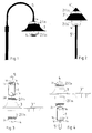
- Fig. 1
- eine Außenleuchte als Hängeleuchte montiert,
- Fig. 2
- eine Außenleuchte formal abgewandelt als Aufsatzleuchte,
- Fig. 3
- in Explosionsdarstellung die Baugruppen und den Zusammenbau der Hängeleuchte gemäß Fig. 1 mit einer zusätzlichen Schirmvariante, und
- Fig. 4
- eine der Fig. 3 vergleichbare Darstellung, wobei der Zusammenbau als Aufsatzleuchte erfolgt.
- Die nach einem Baukasten-System zusammengesetzte Außenleuchte hat als zentrale Baugruppe einen rahmenförmig gestalteten Elektroblock (1) mit allen für den Leuchtenbetrieb erforderlichen elektrischen Bauteilen, wie beispielsweise eine Lampenfassung (1a), ein Vorschaltgerät (1b), und weitere lediglich angedeutete Teile (1c). Auf der Seite des Vorschaltgerätes (1b) ist der anschlußfertig verdrahtete Elektroblock (1) einstückig mit einem Befestigungszapfen (1d) sowie einer kreisförmigen Mastansatzplatte (1e) ausgebildet, die Teil eines den Elektroblock umgebenden vorzugsweise rotationssymmetrischen geschlossenen Gehäuses ist. Im wesentlichen besteht das Gehäuse jedoch aus einer zweigeteilten lichtdurchlässigen Wanne (2) mit einem größeren unteren Wannenteil (2a) für die eigentliche Beleuchtungsaufgabe und einem kleineren oberen Wannenteil (2b) als sekundäre Lichtaustrittsquelle.
- Zwischen den beiden Wannenteilen (2a, 2b) ist umfangsseitig ein lichtundurchlässiger, über die äußere Mantelflache der Wannenteile greifender, ringförmiger Schirm (3) gehalten, der als formales gestalterisches Element dient. Aus verschiedenen Ausführungen (Schirm 3' in Fig. 2, alternative Schirme 3'' in Fig. 3 bzw. 4) läßt sich so innerhalb des Baukasten-Systems der Außenleuchte noch am Einbauort unter Berücksichtigung lichttechnischer Erfordernisse sowie des Wohnumfeldes eine Auswahl treffen oder gegebenenfalls eine Änderung auch nachträglich vornehmen. Zusammengehalten sind die beiden transparenten Wannenteile (2a, 2b) und der zumeist metallische Schirm (3) letztlich mittels einer gewölbten oder kegelförmigen Abschlußschraube (4 bzw. 4'), die der Mastansatzplatte (1e) gegenüberliegend mit dem Elektroblock (1) verschraubt wird und das Gehäuse vervollständigt. Hierbei haben die Abschlußschraube (4, 4') und die Mastansatzplatte (1e) jeweils auf ihrer der Wanne zugekehrten Seite eine gleichartige ringförmige Nut (nicht gezeigt), die über einen an den Wannenteilen geringfügig vorstehenden Randsteg (2c bzw. 2d) greifen. Damit erfolgt neben einer Abdichtung des Gehäuses zugleich die Zentrierung der beiden Wannenteile mit ausreichendem Spiel für Temperaturausgleichsbewegungen.
- Der Zusammenbau der Außenleuchte am zentralen Elektroblock (1) bei einer Hängeleuchte gemäß Fig. 3 erfolgt also durch Aufeinandersetzen von oberen Wannenteil (2b), Schirm (3) bzw. einer Schirmvariante (3', 3'') sowie der unteren Wanne (2a), und durch Festdrehen der Abschlußschraube (4) von Hand. Danach läßt sich die Hängeleuchte mit dem Zapfen (1d) beispielsweise an einem gebogenen Mast (5) gemäß Fig. 1 befestigen.
- Soll die Außenleuchte als Aufsatzleuchte gemäß Fig. 4 zusammengebaut werden, wird der zentrale Elektroblock gedreht, so daß die Mastanschlußplatte mit dem Befestigungszapfen (1d) nach unten zu liegen kommt. Jetzt wird zuerst der untere Wannenteil (2a), danach ein Schirm (3 bzw. 3', 3'') und anschließend der obere Wannenteil (2b) aufgesetzt, und letztlich die Abschlußschraube (4) am zentralen Elektroblock verschraubt. Die Außenleuchte kann danach auf einem geraden Mast (5') gemäß Fig. 2 aufgesetzt und mittels einer nicht gezeigten Schraube befestigt werden.
Claims (5)
- Außenleuchte, die nach einein Baukasten-System aus mehreren Bauteilen zusammengesetzt ist und um einen zentralen Elektroblock (1) mit Lampenfassung (1a) ein mehrteiliges, teilweise durchscheinendes rotationssymmetrisches Gehäuse aufweist, wobei das als zweigeteilte lichtdurchlässige Wanne (2) ausgebildete Gehäuse mit einem ringförmigen Schirm (3) versehen ist, dadurch gekennzeichnet daß der zwischen den beiden Wannenteilen (2a, 2b) angeordnete lichtundurchlässige Schirm (3) wahlweise in verschiedenen Formen und gegebenenfalls auch nachträglich dem Gehäuse zugeordnet, lediglich durch Aufeinandersetzen zusammen mit den Wannenteilen (2a, 2b) zwischen diesen und mittels einer Abschlußschraube (4) am Elektroblock (1) gehalten ist.
- Außenleuchte nach Anspruch 1, dadurch gekennzeichnet, daß die zweigeteilte Wanne (2) aus einem größeren unteren Wannenteil (2a) für die eigentliche Beleuchtungsaufgabe und einem kleineren oberen Wannenteil (2b) als Sekundärlicht zur nächtlichen Formenunterstreichung ausgebildet ist.
- Außenleuchte nach Anspruch 1 oder 2, dadurch gekennzeichnet, daß der Elektroblock (1) mit allen für den Betrieb erforderlichen elektrischen Bauteilen (1a, 1b, 1c) anschlußfertig verdrahtet und einstückig mit einer Mastansatzplatte (1e) ausgebildet ist.
- Außenleuchte nach einem der Ansprüche 1 bis 3, dadurch gekennzeichnet, daß die Abschlußschraube (4) und die Mastansatzplatte (1e) gleichartige Aufnahmemittel für je einen ringförmigen Randsteg (2c, 2d) der beiden an die Aufnahmemittel angepaßten Wannenteile (2a, 2b) aufweisen.
- Außenleuchte nach einem der Ansprüche 1 bis 4, dadurch gekennzeichnet, daß lediglich durch Drehen des Elektroblockes (1) und entsprechenden lagegerechten Zusammenbau der beiden Wannenteile (2a, 2b) und des Schirmes (3) wahlweise eine Aufsatzleuchte oder eine Hängeleuchte herstellbar ist.
Applications Claiming Priority (2)
| Application Number | Priority Date | Filing Date | Title |
|---|---|---|---|
| DE9015063U | 1990-11-02 | ||
| DE9015063U DE9015063U1 (de) | 1990-11-02 | 1990-11-02 | Außenleuchte |
Publications (3)
| Publication Number | Publication Date |
|---|---|
| EP0483626A2 EP0483626A2 (de) | 1992-05-06 |
| EP0483626A3 EP0483626A3 (en) | 1992-09-16 |
| EP0483626B1 true EP0483626B1 (de) | 1995-05-24 |
Family
ID=6858947
Family Applications (1)
| Application Number | Title | Priority Date | Filing Date |
|---|---|---|---|
| EP91117881A Expired - Lifetime EP0483626B1 (de) | 1990-11-02 | 1991-10-19 | Aussenleuchte |
Country Status (3)
| Country | Link |
|---|---|
| EP (1) | EP0483626B1 (de) |
| AT (1) | ATE123127T1 (de) |
| DE (2) | DE9015063U1 (de) |
Families Citing this family (7)
| Publication number | Priority date | Publication date | Assignee | Title |
|---|---|---|---|---|
| DE9106969U1 (de) * | 1991-06-06 | 1992-03-26 | Vulkan Werk für Industrie- und Außenbeleuchtung GmbH, 5000 Köln | Reflektorleuchte |
| FR2689612B1 (fr) * | 1992-04-06 | 1999-02-26 | 3E International | Structure utilisable sur mat ou lampadaire d'eclairage et permettant d'obtenir des effets esthetiques originaux. |
| DE10014471A1 (de) * | 2000-03-23 | 2001-09-27 | Franke Gmbh & Co Kg | Vorrichtung zur Befestigung von Außenleuchten an Masten |
| ITRM20030107A1 (it) * | 2003-03-10 | 2003-06-09 | Giuseppe Pugliese | Illuminatore modulare per tv, cinema, teatro, multifunzionale, versatile e variabile in potenza. |
| CN104141905B (zh) * | 2013-05-07 | 2016-09-07 | 苏州欧普照明有限公司 | 一种灯具 |
| NL2023431B1 (en) * | 2019-07-03 | 2021-02-02 | Schreder Sa | Luminaire head assemblies and methods for assembling luminaire heads |
| EP3994386A1 (de) * | 2019-07-03 | 2022-05-11 | Schreder Sa | Leuchtenkopfanordnungen und verfahren zur montage von leuchtköpfen |
Family Cites Families (9)
| Publication number | Priority date | Publication date | Assignee | Title |
|---|---|---|---|---|
| US1368674A (en) * | 1921-02-15 | Latter | ||
| US1658309A (en) * | 1926-09-27 | 1928-02-07 | Max J Ritterrath | Lamp |
| DE1134161B (de) * | 1961-01-18 | 1962-08-02 | Hanns Willeke | Glockenleuchte mit duennwandigen, nach dem Blasverfahren hergestellten Schirmteilen aus thermoplastischem organischem Kunststoff |
| DE1921111U (de) * | 1965-03-25 | 1965-08-12 | Siemens Ag | Mastaufsatzleuchte mit einer stutzenfoermigen lichtdurchlaessigen abdeckung. |
| DE7931595U1 (de) * | 1979-11-08 | 1980-02-07 | Vulkan Werk Fuer Industrie- Und Aussenbeleuchtung Gmbh, 5000 Koeln | Guertelwabenleuchte |
| FR2505452A1 (fr) * | 1981-05-07 | 1982-11-12 | Pradier Lanternes Roger | Lanterne d'eclairage |
| DE8310324U1 (de) * | 1983-04-08 | 1983-12-08 | Esto Leuchtenfabrik Gesellschaft mbH, 9220 Velden, Kärnten | Aussenleuchte |
| DE8805030U1 (de) * | 1988-04-15 | 1988-06-01 | Siemens AG, 1000 Berlin und 8000 München | Straßenleuchte |
| DE9015062U1 (de) * | 1990-11-02 | 1991-05-29 | Licentia Patent-Verwaltungs-Gmbh, 6000 Frankfurt | Außenleuchte mit einem geschlossenen Gehäuse |
-
1990
- 1990-11-02 DE DE9015063U patent/DE9015063U1/de not_active Expired - Lifetime
-
1991
- 1991-10-19 AT AT91117881T patent/ATE123127T1/de not_active IP Right Cessation
- 1991-10-19 DE DE59105576T patent/DE59105576D1/de not_active Expired - Fee Related
- 1991-10-19 EP EP91117881A patent/EP0483626B1/de not_active Expired - Lifetime
Also Published As
| Publication number | Publication date |
|---|---|
| DE59105576D1 (de) | 1995-06-29 |
| EP0483626A3 (en) | 1992-09-16 |
| DE9015063U1 (de) | 1991-05-29 |
| ATE123127T1 (de) | 1995-06-15 |
| EP0483626A2 (de) | 1992-05-06 |
Similar Documents
| Publication | Publication Date | Title |
|---|---|---|
| EP2539629B1 (de) | Einbauleuchte mit basiskörper und domförmigem reflektor | |
| EP0802369B1 (de) | Lampenabdeckung für eine Aussenleuchte, insbesondere Mast-Aufsetzleuchte | |
| EP1718898B1 (de) | Bodeneinbauleuchte | |
| EP0483626A2 (de) | Aussenleuchte | |
| DE3249401C2 (de) | ||
| DE10037237C2 (de) | Solarleuchte mit einem im wesentlichen kugelförmigen, mindestens teilweise lichtdurchlässigen Leuchtenkörper | |
| DE202011051616U1 (de) | Eine LED-Innenleuchte | |
| DE2341944B2 (de) | Beleuchtungsanlage | |
| DE20205433U1 (de) | Leuchte | |
| EP0770819B1 (de) | Aussenleuchte | |
| DE102007053055A1 (de) | Zeitanzeigeeinrichtung | |
| DE202025104020U1 (de) | Außenleuchte | |
| DE7442071U (de) | Kugelförmige Leuchte | |
| DE10021546C2 (de) | Befestigungsvorrichtung für Hängeleuchten | |
| DE3014287A1 (de) | Mastaufsatzvorrichtung fuer eine seitlich an einem mast anzuordnende leuchte | |
| DE29810886U1 (de) | Anordnung bestehend aus zumindest zwei miteinander verbundenen ringförmigen Körpern sowie Leuchte mit einer solchen Anordnung | |
| DE29705724U1 (de) | Leuchte | |
| DE202005019965U1 (de) | Leuchte | |
| DE2315488B1 (de) | Leuchte | |
| DE19741240A1 (de) | Leuchtenteilgehäuse zur Herstellung eines Leuchtengehäuses | |
| DE4219824A1 (de) | Variabler Leuchtenschirm | |
| DE202004001693U1 (de) | Verbessertes LED-Leuchtelement | |
| DE2511380B2 (de) | GroBraumleuchte | |
| DE19755701A1 (de) | Leuchte | |
| DE2025151A1 (de) | Leuchte |
Legal Events
| Date | Code | Title | Description |
|---|---|---|---|
| PUAI | Public reference made under article 153(3) epc to a published international application that has entered the european phase |
Free format text: ORIGINAL CODE: 0009012 |
|
| AK | Designated contracting states |
Kind code of ref document: A2 Designated state(s): AT BE CH DE FR GB IT LI LU NL |
|
| PUAL | Search report despatched |
Free format text: ORIGINAL CODE: 0009013 |
|
| AK | Designated contracting states |
Kind code of ref document: A3 Designated state(s): AT BE CH DE FR GB IT LI LU NL |
|
| 17P | Request for examination filed |
Effective date: 19920911 |
|
| 17Q | First examination report despatched |
Effective date: 19940405 |
|
| GRAA | (expected) grant |
Free format text: ORIGINAL CODE: 0009210 |
|
| AK | Designated contracting states |
Kind code of ref document: B1 Designated state(s): AT BE CH DE FR GB IT LI LU NL |
|
| REF | Corresponds to: |
Ref document number: 123127 Country of ref document: AT Date of ref document: 19950615 Kind code of ref document: T |
|
| REF | Corresponds to: |
Ref document number: 59105576 Country of ref document: DE Date of ref document: 19950629 |
|
| GBT | Gb: translation of ep patent filed (gb section 77(6)(a)/1977) |
Effective date: 19950605 |
|
| ITF | It: translation for a ep patent filed | ||
| ET | Fr: translation filed | ||
| PGFP | Annual fee paid to national office [announced via postgrant information from national office to epo] |
Ref country code: LU Payment date: 19951001 Year of fee payment: 5 |
|
| PLBE | No opposition filed within time limit |
Free format text: ORIGINAL CODE: 0009261 |
|
| REG | Reference to a national code |
Ref country code: CH Ref legal event code: PUE Owner name: LICENTIA PATENT- VERWALTUNGS-GMBH TRANSFER- PHILIP |
|
| STAA | Information on the status of an ep patent application or granted ep patent |
Free format text: STATUS: NO OPPOSITION FILED WITHIN TIME LIMIT |
|
| 26N | No opposition filed | ||
| REG | Reference to a national code |
Ref country code: GB Ref legal event code: 732E |
|
| NLS | Nl: assignments of ep-patents |
Owner name: PHILIPS ELECTRONICS N.V. |
|
| PG25 | Lapsed in a contracting state [announced via postgrant information from national office to epo] |
Ref country code: LU Free format text: LAPSE BECAUSE OF NON-PAYMENT OF DUE FEES Effective date: 19961019 |
|
| REG | Reference to a national code |
Ref country code: FR Ref legal event code: TP Free format text: CORRECTION |
|
| REG | Reference to a national code |
Ref country code: FR Ref legal event code: CD |
|
| PGFP | Annual fee paid to national office [announced via postgrant information from national office to epo] |
Ref country code: FR Payment date: 20001024 Year of fee payment: 10 |
|
| PGFP | Annual fee paid to national office [announced via postgrant information from national office to epo] |
Ref country code: NL Payment date: 20001030 Year of fee payment: 10 |
|
| PGFP | Annual fee paid to national office [announced via postgrant information from national office to epo] |
Ref country code: GB Payment date: 20001101 Year of fee payment: 10 |
|
| PGFP | Annual fee paid to national office [announced via postgrant information from national office to epo] |
Ref country code: CH Payment date: 20010116 Year of fee payment: 10 |
|
| PG25 | Lapsed in a contracting state [announced via postgrant information from national office to epo] |
Ref country code: GB Free format text: LAPSE BECAUSE OF NON-PAYMENT OF DUE FEES Effective date: 20011019 |
|
| PGFP | Annual fee paid to national office [announced via postgrant information from national office to epo] |
Ref country code: AT Payment date: 20011023 Year of fee payment: 11 |
|
| PGFP | Annual fee paid to national office [announced via postgrant information from national office to epo] |
Ref country code: BE Payment date: 20011030 Year of fee payment: 11 |
|
| PG25 | Lapsed in a contracting state [announced via postgrant information from national office to epo] |
Ref country code: LI Free format text: LAPSE BECAUSE OF THE APPLICANT RENOUNCES Effective date: 20011031 Ref country code: CH Free format text: LAPSE BECAUSE OF THE APPLICANT RENOUNCES Effective date: 20011031 |
|
| PGFP | Annual fee paid to national office [announced via postgrant information from national office to epo] |
Ref country code: DE Payment date: 20011219 Year of fee payment: 11 |
|
| REG | Reference to a national code |
Ref country code: GB Ref legal event code: IF02 |
|
| REG | Reference to a national code |
Ref country code: CH Ref legal event code: PL |
|
| PG25 | Lapsed in a contracting state [announced via postgrant information from national office to epo] |
Ref country code: NL Free format text: LAPSE BECAUSE OF NON-PAYMENT OF DUE FEES Effective date: 20020501 |
|
| GBPC | Gb: european patent ceased through non-payment of renewal fee |
Effective date: 20011019 |
|
| PG25 | Lapsed in a contracting state [announced via postgrant information from national office to epo] |
Ref country code: FR Free format text: LAPSE BECAUSE OF NON-PAYMENT OF DUE FEES Effective date: 20020628 |
|
| NLV4 | Nl: lapsed or anulled due to non-payment of the annual fee |
Effective date: 20020501 |
|
| REG | Reference to a national code |
Ref country code: FR Ref legal event code: ST |
|
| PG25 | Lapsed in a contracting state [announced via postgrant information from national office to epo] |
Ref country code: AT Free format text: LAPSE BECAUSE OF NON-PAYMENT OF DUE FEES Effective date: 20021019 |
|
| PG25 | Lapsed in a contracting state [announced via postgrant information from national office to epo] |
Ref country code: BE Free format text: LAPSE BECAUSE OF NON-PAYMENT OF DUE FEES Effective date: 20021031 |
|
| BERE | Be: lapsed |
Owner name: *KONINKLIJKE PHILIPS ELECTRONICS N.V. Effective date: 20021031 |
|
| PG25 | Lapsed in a contracting state [announced via postgrant information from national office to epo] |
Ref country code: DE Free format text: LAPSE BECAUSE OF NON-PAYMENT OF DUE FEES Effective date: 20030501 |
|
| PG25 | Lapsed in a contracting state [announced via postgrant information from national office to epo] |
Ref country code: IT Free format text: LAPSE BECAUSE OF NON-PAYMENT OF DUE FEES Effective date: 20051019 |