EP0483725B1 - Détecteur de teneur d'alcool - Google Patents
Détecteur de teneur d'alcool Download PDFInfo
- Publication number
- EP0483725B1 EP0483725B1 EP91118353A EP91118353A EP0483725B1 EP 0483725 B1 EP0483725 B1 EP 0483725B1 EP 91118353 A EP91118353 A EP 91118353A EP 91118353 A EP91118353 A EP 91118353A EP 0483725 B1 EP0483725 B1 EP 0483725B1
- Authority
- EP
- European Patent Office
- Prior art keywords
- light
- current
- output
- fuel
- detector
- Prior art date
- Legal status (The legal status is an assumption and is not a legal conclusion. Google has not performed a legal analysis and makes no representation as to the accuracy of the status listed.)
- Expired - Lifetime
Links
Images



Classifications
-
- G—PHYSICS
- G01—MEASURING; TESTING
- G01N—INVESTIGATING OR ANALYSING MATERIALS BY DETERMINING THEIR CHEMICAL OR PHYSICAL PROPERTIES
- G01N21/00—Investigating or analysing materials by the use of optical means, i.e. using sub-millimetre waves, infrared, visible or ultraviolet light
- G01N21/17—Systems in which incident light is modified in accordance with the properties of the material investigated
- G01N21/41—Refractivity; Phase-affecting properties, e.g. optical path length
- G01N21/4133—Refractometers, e.g. differential
-
- G—PHYSICS
- G01—MEASURING; TESTING
- G01N—INVESTIGATING OR ANALYSING MATERIALS BY DETERMINING THEIR CHEMICAL OR PHYSICAL PROPERTIES
- G01N21/00—Investigating or analysing materials by the use of optical means, i.e. using sub-millimetre waves, infrared, visible or ultraviolet light
- G01N21/17—Systems in which incident light is modified in accordance with the properties of the material investigated
- G01N2021/1765—Method using an image detector and processing of image signal
- G01N2021/177—Detector of the video camera type
- G01N2021/1772—Array detector
-
- G—PHYSICS
- G01—MEASURING; TESTING
- G01N—INVESTIGATING OR ANALYSING MATERIALS BY DETERMINING THEIR CHEMICAL OR PHYSICAL PROPERTIES
- G01N21/00—Investigating or analysing materials by the use of optical means, i.e. using sub-millimetre waves, infrared, visible or ultraviolet light
- G01N21/84—Systems specially adapted for particular applications
- G01N2021/8405—Application to two-phase or mixed materials, e.g. gas dissolved in liquids
-
- Y—GENERAL TAGGING OF NEW TECHNOLOGICAL DEVELOPMENTS; GENERAL TAGGING OF CROSS-SECTIONAL TECHNOLOGIES SPANNING OVER SEVERAL SECTIONS OF THE IPC; TECHNICAL SUBJECTS COVERED BY FORMER USPC CROSS-REFERENCE ART COLLECTIONS [XRACs] AND DIGESTS
- Y10—TECHNICAL SUBJECTS COVERED BY FORMER USPC
- Y10T—TECHNICAL SUBJECTS COVERED BY FORMER US CLASSIFICATION
- Y10T436/00—Chemistry: analytical and immunological testing
- Y10T436/20—Oxygen containing
- Y10T436/203332—Hydroxyl containing
- Y10T436/204165—Ethanol
Definitions
- the invention relates to a device for detecting an alcoholic content in fuel according to the preamble of claim 1.
- a device for detecting an alcoholic content in fuel according to the preamble of claim 1.
- a one-dimensional light position detector element is used to send an index of fraction of fuel in accordance with the position at which the light impinges on the position detector element.
- no measures are provided in order to avoid an incorrect measurement of the refractive index when accidentally bubbles are present in the fuel.
- WO 89/01796 discloses a bubble detector in which the fuel is passed through a tappet section and a light transmission measurement is performed at a portion with a smallest cross section. When a bubble is present in the fuel and the bubble is pushed to the portion with the smallest cross section, then a total received light amount by a detector increases which indicates the presence of a bubble.
- Such devices for detecting an alcoholic content are particularly useful for determining the nature of the fuel supplied to a burner or like in a non-contact manner.
- Such fuel alcohol content measurement is particularly useful to determining the alcohol in fuel used in an engine for automobiles or the like.
- Fig. 5 is a schematic diagram illustrating an engine control system having incorporated therein a conventional alcoholic content detector device.
- A designates an alcohol content detector
- (20) is an engine
- (21) is a fuel tank
- (22) is a fuel pump disposed within the fuel tank (21)
- (23) is a fuel supply pipe connected to the fuel pump (22)
- (24) is a high pressure filter inserted in the fuel supply pipe (23)
- (25) is a fuel distributor connected to the fuel supply pipe (23)
- (26) is a fuel pressure regulator connected to the fuel distributor (26)
- (27) is a fuel injection valve connected to the fuel distributor (25)
- (28) is a fuel return pipe connected to the fuel pressure regulator (26)
- (29) is an intake pressure sensor connected to an air intake pipe (30)
- (31) is an air-to-fuel ratio sensor mounted to an exhaust pipe (32)
- (33) is an engine revolution sensor
- (34) is an ignition plug mounted to the engine (34)
- (35) is an engine control unit
- the fuel then flows into the fuel distributor pipe (25) and one portion thereof is supplied to the engine (20) through the fuel injection valve (27) and the remaining portion is returned to the fuel tank (21) through the fuel pressure regulator (26) and the fuel return pipe (28).
- the fuel pressure regulator (26) functions to maintain the fuel pressure in the pipe up to the fuel pressure regulator (26) constant irrespective of the amount of injected fuel.
- the engine control unit (35) determines the engine conditions on the basis of the signals from the engine rotation sensor (33) and the air intake pressure sensor (29) to control the valve-open time of the fuel injection valve (27), thereby changing the fuel amount supplied to the engine (20), and the air-to-fuel ratio is detected by the air-to-fuel ratio sensor (31) so that it is feed-back controlled toward a target value corresponding to the above engine conditions, upon which the ignition timing of the ignition plug (34) is controlled in accordance with the engine conditions.
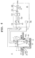
- Fig. 6 is a schematic diagram illustrating a conventional alcohol content detector, in which (1) is a light emitting element, (2) is a diaphragm disposed in front of the light emitting element (1), (3) is a collecting lens disposed in front of the diaphragm (2), (4) is a collected light beam and (5) is a cylindrical transparent body having formed thereon a retraction surface (51) which is cut at a predetermined angle relative to its longitudinal axis and which is in contact with the fuel introduced from the fuel inlet (81), (6) is a back side reflection mirror having a reflection surface on the opposite side of the fuel-contacting surface, (7) is a first dimension position detector element, which in this example is a semiconductor position detector element (hereinafter referred to as PSD), (8) is a case having formed therein the fuel inlet (81) for introducing the fuel onto the refraction surface (51) of the cylindrical transparent body (5), (9) is a seal including a seal portion (91) which seals between the cylindrical transparent body (5) and the case (8) and
- the refracted light passes through the fuel and reflected at the reflection surface P1 on the back side reflection mirror (6) to again, pass through the fuel and impinges again at a point P2 on the refraction surface (51), where the light refracts in accordance with the above equation between the incident angle ⁇ and the refraction angle X to pass into the cylindrical transparent body (5) and reach the PSD (7) disposed on the same side of the light emitting element (1).
- the collection lens (3) is adjusted so that the collected light beam (4) is focused substantially on the PSD (7).
- Each of the photo-currents ir1 and ir2 is inputted to the detector circuit (10) and current-voltage converted into Vr1 and Vr2, respectively, in the current-voltage conversion unit (101).
- the voltages Vr1 and Vr2 are added in the adder (102) and the divider (104) computes Vr1 / (Vr1 + Vr2) on the basis of the voltage Vr1 and the result of the above addition.
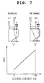
- Fig. 7 is a graph illustrating the output characteristics of the alcohol content detector in connection with a methanol-gasoline mixed fuel, from which it is seen that, when the alcohol content is 0%, i.e., pure gasoline only, the difference in retraction index between the gasoline and the cylindrical transparent body (5) is small, so that the collected light beam (4) impinges on the PSD (7) on the side close to the light emitting element (1) to establish the relationship ir1 ⁇ ir2, and when the alcohol content is 100%, i.e., pure methanol only, the difference in refraction index between the gasoline and the cylindrical transparent body (5) is large, so that the collected light beam (4) impinges on the PSD (7) on the side remote from the light emitting element (1) to establish the relationship ir1 > ir2, whereby the illustrated output characteristic is obtained.
- the fuel pressure in the high pressure pipe decreases and bubbles generate within the pipe, establishing a state in which bubbles exist within the fuel at the time of re-starting the engine, and when the alcohol content detector is connected in the fuel return pipe (28) at the downstream of the fuel pressure regulator (26), the fuel containing bubbles generated by the cavitation phenomenon at the fuel pressure regulator (26) passes through the alcohol content detector.
- the alcohol content detector is connected in the fuel return pipe (28) at the downstream of the fuel pressure regulator (26)
- the fuel containing bubbles generated by the cavitation phenomenon at the fuel pressure regulator (26) passes through the alcohol content detector.
- the bubbles mixed within the fuel cannot be detected even when they passed through the detection unit of the detector and the output change due to the passage of the the bubbles is erroneously recognized as the change in alcohol content.
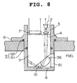
- Fig. 8 is a sectional view of the detection unit of the conventional alcohol content detector, which illustrates the state in which the bubbles (36) in the fuel introduced from the fuel inlet (81) are in the vicinity of the refraction surface (51) of the cylindrical transparent body (5).
- the collected light beam (4) passing through the cylindrical transparent body (5) is refracted at a large angle at the refraction surface (51) and is scattered or absorbed at the casing (8) and the like, so that only a very weak scattered light or no light at all impinges at the PSD (7), causing the output Vout to exhibit an unstable value which does not depend upon the alcohol content.
- the output variation due to the bubbles and the output alcohol cannot be distinguished from each other, so that change in output due to the bubbles is erroneously recognized as the output change due to the change in alcohol content and the engine fuel amount, the ignition timing and the like are controlled. Therefore, there was a fear that a malfunction of the engine such as non-smooth starting of the engine and an abrupt engine stall may occur depending upon the conditions of the bubbles.
- the present invention has been made in order to solve the above problems and has as its object to provide an alcohol content detector capable of detecting bubbles within the fuel without erroneously recognizing the change in the alcohol content.
- a device for detecting alcoholic content comprises a light emitting element disposed on one side of a light transparent body, a first dimension optical position detector element disposed on the same or opposite side of the transparent body, an alcohol content detector having formed in one part of the transparent body a refraction surface with respect to fuel, with light introduced into the retraction surface from the light-emitting element to cause the light beam to refract at least once and to impinge upon the first dimensional optical position detector element, for detecting index of refraction of fuel in accordance with the position at which the light impinges on the first dimension optical position detector element, a total light-receiving amount detector for detecting the total light-receiving amount of the first dimension position detector, and a bubble detector for detecting bubbles in the fuel in accordance with the relative value relationship between the total light-receiving amounts.
- a device for detecting alcoholic content comprises a light emitting element disposed one side of a light transparent body, a first dimension optical position detector element disposed on the same or opposite side of the transparent body, an alcohol content detector having formed in one part of the transparent body a refraction surface with respect to fuel, light is introduced into the refraction surface from the light-emitting element to cause the light beam to refract at least once and to impinge upon the first dimensional optical position detector element, for detecting index of refraction of fuel in accordance with the position at which the light impinges on the first dimension optical position detector element, a total light-receiving amount detector for detecting the total light-receiving amount of the first dimension position detector, a monitor unit for monitoring emission of light of the light-emitting element, and a bubble detector for detecting bubbles in the fuel in accordance with the relative value relationship between the total light-receiving amount and an output from the monitor.
- the device for detecting alcoholic content comprises a light emitting element disposed one side of a light transparent body, a first dimension optical position detector element disposed on the same or opposite side of the transparent body, an alcohol content detector having formed in one part of the transparent body a refraction surface with respect to fuel, light being introduced into the refraction surface from the light-emitting element to cause the light beam to refract at least once and to impinge upon the first dimensional optical position detector element, for detecting index of refraction of fuel in accordance with the position at which the light impinges on the first dimension optical position detector element, a total light-receiving amount detector for detecting the total light-receiving amount of the first dimension position detector, a light-emitting element control unit for controlling the light-emitting element so that an output from the total light-receiving amount detector unit is maintained constant, and bubble detector means for detecting bubbles in the fuel in accordance with the relative value relationship between output
- the light emitted from the light emitting element is introduced to the refraction surface formed in one part of the transparent body to cause the light beam to refract at least once and to impinge upon the first dimensional optical position detector element, thereby detecting index of refraction of fuel in accordance with the position at which the light beam impinges on the first dimension optical position detector element and detecting bubbles in the fuel in accordance with the relative value relationship between the total light-receiving amounts.
- the index of refraction of the fuel is detected in accordance with the position at which the light impinges on the first dimension optical position detector element, end the monitor for monitoring the light emission from the light emitting element is provided, and detecting bubbles in the fuel, in accordance with the relative value relationship between the total light-receiving amount and an output from the monitor means.
- the index of refraction of the fuel is detected in accordance with the position at which the light impinges on the first dimension optical position detector element, and the light-emitting element is controlled by the light-emitting element control means so that the output from the total light-receiving amount detector means is maintained constant, and the bubbles in the fuel is detected in accordance with the relative value relationship between output signals from the light-emitting element control means.
- Fig. 1 is a schematic diagram illustrating one embodiment of the present invention, in which (101) ⁇ (106) are components similar to those previously described. Also, the detection unit (1) ⁇ (9) are not illustrated because they are identical to those of the conventional device.
- (107) is a comparator of which inverse input terminal is connected to an output of the adder (102) and non-inverse input terminal is connected to a d.c. power source having a voltage value of Vmin, (108) is an output controlled transistor having a base connected to an output of the comparator (107) , a collector connected to an output of the output bias setting unit (105) and an emitter connected to the earth.
- Fig. 7 when the light emitting element (1) is driven by the driving unit (106) to emit light, the emitted light is passed through the diaphragm (2) and collected by the collection lens (3).
- the collected light beam (4) impinges at the refraction surface (51) contacting with the fuel at the other end of the cylindrical transparent body (5) at the point Po at an incident angle ⁇ to refract at the refraction surface (51) at a refraction angle X determined in accordance with the difference between the index of refraction Nf of the fuel and the index of refraction Nd of the cylindrical transparent body (5).
- the refracted light passes through the fuel and reflected at the reflection surface P1 on the back side reflection mirror (6) to again pass through the fuel and impinges on the refraction surface (51) at the point P2, where the light retracts to enter into the cylindrical transparent body (5) and is focused on the PSD (7) disposed on the same side of the light emitting element (1).
- the signal light becomes the divided photo-currents ir1 and ir2 divided in correspondence with the position of incidence X and outputted from the electrodes I1 and I2.
- the photo-currents ir1 and ir2 are inputted to the detector circuit (10A) and current-voltage converted into Vr1 and Vr2, respectively, in the current-voltage conversion unit (101).
- the voltages Vr1 and Vr2 are added in the adder (102) and the divider (104) computes Vr1 / (Vr1 + Vr2) on the basis of the voltage Vr1 and the result of the above addition.
- the computation result is multiplied by an output voltage gain K in the output gain setting unit (103), and a predetermined voltage bias Vo is applied at the output bias setting unit (105), whereby a voltage Vout corresponding to alcohol content Cm is outputted.
- the collected light beam (4) passing through the cylindrical transparent body (5) is refracted at the refraction surface (51) at a large angle and is scattered or absorbed at the casing (5) and the like, so that only a very weak scattered light or no light at all impinges at the PSD (7), causing the divided currents ir1 and ir2 to have only a very small dark current component due to temperature and the photo-current component generated by the weak scattered light, resulting in very small current as compared to the currents in the ordinary conditions in which the detection unit is filled with the fuel.
- the divided currents ir1 and ir2 when such bobble (36) stays are current-voltage converted into Vr1 and Vr2, respectively, in the current-voltage conversion unit (101) and then added by the adder (102), and the result of the above addition, i.e., the total photo-current value (Vr1 + Vr2) is compared with a predetermined voltage value Vmin at the comparator (107).
- Vmin a predetermined voltage value
- FIG. 2 is a graph illustrating the output Vout of the alcohol content detector of the above embodiment when the engine (20) is started with the bubbles contained in the fuel system as compared to that of the conventional device, from which it is understood that, while the output variation due to the bubbles cannot be distinguished from that due to the variation in the alcohol content in the convention device, the bubble detection can be achieved by the LOW state of the output Vout in this embodiment, so that there is no fear of erroneously recognizing the output variation due to the bubbles as the variation in the alcohol content.
- Fig. 3 is a schematic diagram illustrating another embodiment of the present invention, the description will be made with the same reference numerals assigned to the corresponding components shown in Fig. 1.
- the detection circuit (10B) of this embodiment comprises a total received light amount gain setting unit (109), a light emission current detection unit (110) and a subtractor unit (111) all connected to the inputs of the comparator (107).
- One of the inputs of the subtractor unit (111) is connected to the output of the adder unit (102) through the total received light amount gain setting unit (109), the other input of the subtractor unit (111) is connected to the light emitting element (1) through the light emission current detection unit (110), and the output of the subtractor (111) is connected to the inverse input terminal of the comparator (107).
- a resistor R is connected between the input of the light emission current detector unit (119) and the ground.
- bubbles in the fuel are detected on the basis of the magnitude relationship with respect to the light emission current of the light emitting element (1), whereby it is advantageously distinguished from the condition in which the normal light emission is not achieved because of the mulfunction of the light emitting element (1) or the like.
- the mulfunction of the light emitting element (1) or the like can be determined when the light emission current is zero even when the output Vout is not in the LOW state by externally taking out the signal from the light emission current detection unit (111).
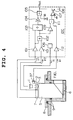
- Fig. 4 is a schematic diagram illustrating another embodiment of the present invention.
- a monitor light receiving element (37) is provided in the vicinity of the light emitting element (1) for monitoring the light emitting state of the light emitting element (1) and for supplying the output from the monitor light receiving element (37) to the other input of the subtraction unit (111) through the monitor light receiving amount detector unit (112) of the detection circuit (10C).
- the light receiving amount im of the monitor light receiving element (37) is detected by the monitor light receiving amount detector unit (112), and this value is subtracted in the subtraction unit (111) from a total light receiving amount of the PSD (7) multiplied by a predetermined gain k' by the total light receiving amount gain setting unit (109), and the subtraction result [ k'(Vr1 + Vr2) - im ] is compared in the comparator (107).
- the output control transistor (108) is turned on to decrease the output Vout to LOW in a similar manner to that in the previous embodiments.
- the device for detecting alcoholic content of the first aspect of the invention invention comprises a light emitting element disposed on one side of a light transparent body, a first dimension optical position detector element disposed on the same or opposite side of the transparent body, an alcohol content detector having formed in one part of the transparent body a refraction surface with respect to fuel, with light introduced into the refraction surface from the light-emitting element to cause the light beam to refract at least once and to impinge upon the first dimensional optical position detector element, for detecting index of refraction of fuel in accordance with the position at which the light impinges on the first dimension optical position detector element, a total light-receiving amount detector for detecting the total light-receiving amount of the first dimension position detector, and a bubble detector for detecting bubbles in the fuel in accordance with the relative value relationship between the total light-receiving amounts. Therefore, an alcohol content detector capable of accurately detecting the alcohol content even when bubbles are contained within the fuel.
- the device for detecting alcoholic content of the second aspect of the invention comprises a light emitting element disposed one side of a light transparent body, a first dimension optical position detector element disposed on the same or opposite side of the transparent body, an alcohol content detector having formed in one part of the transparent body a refraction surface with respect to fuel, light is introduced into the refraction surface from the light-emitting element to cause the light beam to refract at least once and to impinge upon the first dimensional optical position detector element, for detecting index of refraction of fuel in accordance with the position at which the light impinges on the first dimension optical position detector element, a total light-receiving amount detector for detecting the total light-receiving amount of the first dimension position detector, a monitor unit for monitoring emission of light of the light-emitting element, and a bubble detector for detecting bubbles in the fuel in accordance with the relative value relationship between the total light-receiving amount and an output from the monitor. Therefore, an alcohol content detector capable of accurately detecting
- the device for detecting alcoholic content of the third aspect of the invention comprises a light emitting element disposed one side of a light transparent body, a first dimension optical position detector element disposed on the same or opposite side of the transparent body, an alcohol content detector having formed in one part of the transparent body a refraction surface with respect to fuel, light being introduced into the refraction surface from the light-emitting element to cause the light beam to refract at least once and to impinge upon the first dimensional optical position detector element, for detecting index of refraction of fuel in accordance with the position at which the light impinges on the first dimension optical position detector element, a total light-receiving amount detector for detecting the total light-receiving amount of the first dimension position detector, a light-emitting element control unit for controlling the light-emitting element so that an output from the total light-receiving amount detector unit is maintained constant, and bubble detector means for detecting bubbles in the fuel in accordance with the relative value relationship between output signals from the light-emit
Landscapes
- Physics & Mathematics (AREA)
- Health & Medical Sciences (AREA)
- Life Sciences & Earth Sciences (AREA)
- Chemical & Material Sciences (AREA)
- Analytical Chemistry (AREA)
- Biochemistry (AREA)
- General Health & Medical Sciences (AREA)
- General Physics & Mathematics (AREA)
- Immunology (AREA)
- Pathology (AREA)
- Investigating Or Analysing Materials By Optical Means (AREA)
- Combined Controls Of Internal Combustion Engines (AREA)
Claims (16)
- Dispositif de détection d'une teneur en alcool, Cm, dans un liquide, comprenant :a) un elément d'émission de lumière (1) disposé sur un côté d'un corps transparent à la lumière (5) et émettant un faisceau de lumière (4) ;b) un élément de détection de position du faisceau de lumière (17) disposé sur le même côté ou sur le côté opposé du corps transparent (5) ;c) un moyen de circuit de détection de la teneur en alcool (10A-10C) comprenant une surface de réfraction (6), dans lequel ledit faisceau de lumière (4) dudit élément d'émission de lumière (1) est introduit dans ladite surface de réfraction (6) pour faire en sorte qu'il se réfracte au moins une fois et pour se heurter audit élément de détection de position (7), afin de détecter l'indice de réfraction, Nf, du liquide selon la position à laquelle la lumière heurte ledit élément de détection de position (7) ; etd) un moyen de détection de la quantité totale de réception de lumière (101 ; 102) destiné à détecter la quantité totale de réception de lumière dudit détecteur de position (7) et à créer une valeur de courant photoélectrique totale correspondant à celle-ci ;
caractérisé pare) un moyen de détection de bulles pour détecter les bulles (36) dans ledit liquide ;f) ledit moyen de détection de bulles comprend un comparateur (107)pour comparer une valeur fondée sur ladite valeur de courant photoélectrique totale à une valeur prédéterminée ; etpour créer une sortie de détection de bulle lorsque ladite valeur chute en dessous de ladite valeur prédéterminée. - Dispositif selon la revendication 1,
caractérisé en ce queledit moyen de détection de la quantité totale de réception de lumière (101 ; 102) comprend deux unités de conversion courant-tension (101) destinées à convertir deux courants photoélectriques (ir1, ir2) correspondant à ladite quantité totale de réception de lumière dudit élément de détection de position en deux tensions correspondantes, Vr1, Vr2, et un additionneur (102) destiné à additionner les deux tensions, Vr1, Vr2, et à sortir en tant que valeur de courant photoélectrique totale une valeur totale de tension de courant photoélectrique, Vr1+Vr2, correspondant à ladite addition. - Dispositif selon la revendication 2,
caractérisé en ce queledit comparateur (107)compare ladite valeur sortie, Vr1+Vr2, dudit additionneur (102), à une valeur de tension prédéterminée, Vmin ; etcrée ladite sortie de détection de bulle lorsque ladite valeur de tension de courant photoélectrique, Vr1+Vr2, chute en dessous de ladite valeur prédéterminée, Vmin. - Dispositif selon la revendication 2,
caractérisé parledit moyen de détection de la quantité totale de réception de lumière (101 ; 102) comprenant en outre une unité établissant le gain de quantité totale de lumière reçue (109) multipliant ladite valeur de sortie Vr1+Vr2, par un gain prédéterminé, K,une unité de détection de courant d'émission de lumière (110) détectant un courant de commande, it, dudit élément d'émission de lumière (1), et créant une sortie correspondante, it ;un soustracteur (111) destiné à soustraire ledit courant de sortie, it, de ladite unité de détection de courant de lumière (11=) de la sortie de ladite unité établissant le gain (109) et à sortir un résultat soustrait correspondant de courant :ledit comparateur (107) qui compare ledit résultat soustrait de courant,la création de ladite sortie de détection de bulle lorsque ledit résultat soustrait de courant, - Dispositif selon la revendication 2,
caractérisé parledit moyen de détection de la quantité totale de réception de lumière (101 ; 102) comprenant en outre une unité établissant le gain de quantité totale de lumière (109) multipliant ladite tension du courant photoélectrique, Vr1+Vr2, par un gain prédéterminé, K',un moyen formant moniteur (37, 112) de réception de lumière sortant un courant de sortie, im, correspondant à ladite émission de lumière dudit élément d'émission de lumière (1), etun soustracteur (111) destiné à soustraire ledit courant de sortie, im, dudit moyen formant moniteur (37, 112) de réception de la lumière depuis la sortie de ladite unité établissant le gain (109) et sortant un résultat de courant de soustraction correspondant,ledit comparateur (107) comparant ledit résultat de courantla création de ladite sortie de détection de bulles lorsque ledit résultat du courant de soustraction, - Dispositif selon les revendications 2 et 5,
caractérisé en ce queledit comparateur (107)compare ladite valeur de tension de courant photoélectrique (Vr1+Vr2) à une valeur de tension prédéterminée (Vmin) ; etcrée ladite sortie de détection de bulles lorsque ladite valeur dudit courant photoélectrique (Vr1+Vr2) chute en dessous de ladite valeur prédéterminée (Vmin). - Dispositif selon les revendications 3 et 5,
caractérisé parledit moyen de détection de la quantité totale de lumière reçue (101-102, 109) comprenant en outre une unité établissant le gain de la quantité totale de lumière reçue (109) multipliant ladite valeur de tension du courant photoélectrique (Vr1+Vr2) par un gain prédéterminé, (K),ladite unité de détection de courant d'émission de lumière (110) sortant un courant de sortie (it) correspondant audit courant de commande détecté (it) dudit élément d'émission de lumière (1), etun soustracteur (111) destiné à soustraire ledit courant de sortie (it) de ladite unité de détection du courant d'émission de lumière (110) de la sortie (K(Vr1+Vr2)) de ladite unité établissant le gain de quantité totale de lumière reçue (109) et sortant un résultat correspondant de courant soustrait ( - Dispositif selon la revendication 7,
caractérisé en ce queledit comparateur (107)compare ledit résultat de courant soustrait (crée ladite sortie de détection de bulle lorsque ledit résultat de courant soustrait ( - Dispositif selon les revendications 4 et 5,
caractérisé parledit moyen de détection de la quantité totale de lumière reçue (101-102, 109) comprenant en outre une unité établissant le gain de la quantité totale de lumière reçue (109) multipliant ladite valeur de tension de courant photoélectrique (Vr1+Vr2) par un gain prédéterminé (K'),ledit moyen formant moniteur (37, 112) de réception de la lumière sortant un courant de sortie (im) correspondant à ladite émission de lumière dudit élément d'émission de lumière (1), etun soustracteur (111) destiné à soustraire le courant de sortie (im) dudit moyen formant moniteur de réception de la lumière (37, 112) de la sortie (K'(Vr1+vr2)) de ladite unité établissant le gain de la quantité totale de lumière reçue (109) et sortant un résultat correspondant de soustraction de courant ( - Dispositif selon la revendication 9,
caractérisé en ce queledit comparateur (107)compare ledit résultat de soustraction de courant (crée ladite sortie de détection de bulles lorsque ledit résultat de soustraction de courant ( - Dispositif selon la revendication 5,
caractérisé en ce queledit premier élément de détection de dimension de la position optique (7, I1, I2) comprend deux électrodes (I1, I2) créant lesdits deux courants photoélectriques (ir1, ir2), correspondant respectivement à la circulation de la quantité de lumière entrant dans celles-ci. - Dispositif selon la revendication 5,
caractérisé en ce queun diviseur (103) est présent pour sortir une tension divisée, - Dispositif selon la revendication 12,
Caractérisé en ce queUn circuit de réglage du gain de sortie (104) est prévu pour multiplier ladite tension divisée, - Dispositif selon la revendication 13,
caractérisé en ce queun circuit de réglage de la polarisation de sortie (105) est prévu pour régler une polarisation prédéterminée de tension (Vo) à ladite sortie du circuit de réglage du gain de sortie (104) et pour sortir une tension de sortie (Vsortie) correspondant à ladite teneur en alcool (Cm). - Dispositif selon la revendication 14,
caractérisé en ce queledit moyen de détection de bulles (107, 108) comprend en outre un transistor de commande (108) qui diminue ladite tension de sortie (Vsortie) dudit circuit de réglage de polarisation de sortie (105) jusqu'à "LOW" lorsque ledit comparateur (107) sort ladite sortie de détection de bulles. - Dispositif selon la revendication 11,
caractérisé en ce queledit moyen de détection de la teneur en alcool (51, 6, 81, 101-105) est adapté, de sorte qu'une bulle de carburant (36) provoque une réfraction dudit faisceau de lumière (4) au niveau d'une surface de réfraction (51) dudit corps transparent (5), de sorte qu'il est dispersé ou absorbé au niveau dudit corps transparent (5) et que seulement de la lumière dispersée très faible ou qu'aucune lumière du tout ne heurte ledit premier élément de détection de dimension de la position optique (7, I1, I2) faisant en sorte que lesdits courants photoélectriques (ir1, ir2) sortis desdites électrodes (I1, I2) possèdent seulement un petit composant de courant d'obscurité.
Applications Claiming Priority (3)
| Application Number | Priority Date | Filing Date | Title |
|---|---|---|---|
| JP293570/90 | 1990-11-01 | ||
| JP29357090 | 1990-11-01 | ||
| JP2293570A JPH04169839A (ja) | 1990-11-01 | 1990-11-01 | アルコール含有率検知装置 |
Publications (3)
| Publication Number | Publication Date |
|---|---|
| EP0483725A2 EP0483725A2 (fr) | 1992-05-06 |
| EP0483725A3 EP0483725A3 (en) | 1993-05-05 |
| EP0483725B1 true EP0483725B1 (fr) | 2000-02-02 |
Family
ID=17796453
Family Applications (1)
| Application Number | Title | Priority Date | Filing Date |
|---|---|---|---|
| EP91118353A Expired - Lifetime EP0483725B1 (fr) | 1990-11-01 | 1991-10-28 | Détecteur de teneur d'alcool |
Country Status (4)
| Country | Link |
|---|---|
| US (1) | US5234666A (fr) |
| EP (1) | EP0483725B1 (fr) |
| JP (1) | JPH04169839A (fr) |
| DE (1) | DE69131952T2 (fr) |
Families Citing this family (12)
| Publication number | Priority date | Publication date | Assignee | Title |
|---|---|---|---|---|
| SE9602960D0 (sv) | 1996-08-09 | 1996-08-09 | Siemens Elema Ab | Narkosvätskeidentifiering |
| EP2286918B1 (fr) * | 1998-01-12 | 2014-10-01 | Massachusetts Institute of Technology | Procédé d' analyse d' une pluralite d' échantillons |
| US6893877B2 (en) | 1998-01-12 | 2005-05-17 | Massachusetts Institute Of Technology | Methods for screening substances in a microwell array |
| NZ513390A (en) | 1999-03-19 | 2003-01-31 | Genencor Int | Multi-through hole testing plate for high throughput screening |
| WO2001061054A2 (fr) * | 2000-02-18 | 2001-08-23 | Board Of Trustees Of The Leland Stanford Junior University | Appareils et procedes de conduite en parallele de reactions sur des microvolumes |
| US20020151040A1 (en) | 2000-02-18 | 2002-10-17 | Matthew O' Keefe | Apparatus and methods for parallel processing of microvolume liquid reactions |
| US8277753B2 (en) | 2002-08-23 | 2012-10-02 | Life Technologies Corporation | Microfluidic transfer pin |
| WO2004074818A2 (fr) | 2002-12-20 | 2004-09-02 | Biotrove, Inc. | Appareil et procede de dosage utilisant des reseaux microfluidiques |
| CA2559171A1 (fr) | 2004-03-12 | 2005-09-29 | Biotrove, Inc. | Chargement d'ensembles d'echantillons de l'ordre du nanolitre |
| US20060105453A1 (en) | 2004-09-09 | 2006-05-18 | Brenan Colin J | Coating process for microfluidic sample arrays |
| US12070731B2 (en) | 2004-08-04 | 2024-08-27 | Life Technologies Corporation | Methods and systems for aligning dispensing arrays with microfluidic sample arrays |
| JP4465725B2 (ja) * | 2008-04-04 | 2010-05-19 | 株式会社デンソー | 液体用濃度測定装置 |
Citations (2)
| Publication number | Priority date | Publication date | Assignee | Title |
|---|---|---|---|---|
| DE3716793A1 (de) * | 1986-02-19 | 1988-12-08 | Ngk Spark Plug Co | Sensor fuer das mischungsverhaeltnis von benzin und alkohol oder dergleichen |
| DE4103873A1 (de) * | 1990-02-08 | 1991-08-14 | Mitsubishi Electric Corp | Geraet zur erfassung der alkoholkonzentration |
Family Cites Families (4)
| Publication number | Priority date | Publication date | Assignee | Title |
|---|---|---|---|---|
| GB8720454D0 (en) * | 1987-08-28 | 1987-10-07 | Bellhouse Techn Ltd | Bubble detector |
| US4853551A (en) * | 1987-10-30 | 1989-08-01 | Micromeritics Instrument Corporation | Safety interlock for x-ray particle size analyzer |
| US4920550A (en) * | 1987-10-30 | 1990-04-24 | Micromeritics Instrument Corporation | X-ray particle size analyzer |
| US5015091A (en) * | 1988-04-13 | 1991-05-14 | Mitsubishi Denki K.K. | Device for detecting alcoholic content |
-
1990
- 1990-11-01 JP JP2293570A patent/JPH04169839A/ja active Pending
-
1991
- 1991-10-28 EP EP91118353A patent/EP0483725B1/fr not_active Expired - Lifetime
- 1991-10-28 DE DE69131952T patent/DE69131952T2/de not_active Expired - Fee Related
- 1991-10-30 US US07/785,061 patent/US5234666A/en not_active Expired - Fee Related
Patent Citations (2)
| Publication number | Priority date | Publication date | Assignee | Title |
|---|---|---|---|---|
| DE3716793A1 (de) * | 1986-02-19 | 1988-12-08 | Ngk Spark Plug Co | Sensor fuer das mischungsverhaeltnis von benzin und alkohol oder dergleichen |
| DE4103873A1 (de) * | 1990-02-08 | 1991-08-14 | Mitsubishi Electric Corp | Geraet zur erfassung der alkoholkonzentration |
Also Published As
| Publication number | Publication date |
|---|---|
| JPH04169839A (ja) | 1992-06-17 |
| DE69131952D1 (de) | 2000-03-09 |
| EP0483725A3 (en) | 1993-05-05 |
| US5234666A (en) | 1993-08-10 |
| EP0483725A2 (fr) | 1992-05-06 |
| DE69131952T2 (de) | 2000-06-15 |
Similar Documents
| Publication | Publication Date | Title |
|---|---|---|
| KR910004217B1 (ko) | 알콜함유율 검출장치 | |
| US5234666A (en) | Alcohol content detector | |
| US8089629B2 (en) | Fuel property detection apparatus | |
| US5110205A (en) | Apparatus for detecting alcohol concentration | |
| EP0441056B1 (fr) | Palpeur optique pour la détermination de la composition d'un combustible | |
| US4444169A (en) | Air-fuel ratio controlling device for internal combustion engines | |
| US7605361B2 (en) | Fuel property detection device | |
| EP2729677B1 (fr) | Dispositif de mesure de la concentration d'uree | |
| US4895444A (en) | Detector device for mixing ratio for gasoline and alcohol or the like | |
| JPS6291840A (ja) | 燃料性状検出器 | |
| JPH0440343A (ja) | アルコール含有率検知装置 | |
| EP0433080B1 (fr) | Dispositif pour mesurer le rapport de mélange de plusieurs liquides | |
| US4912319A (en) | Detector device for mixing ratio for gasoline and alcohol or the like | |
| JP3250491B2 (ja) | 内燃機関の空燃比検出装置 | |
| JPS6039527A (ja) | 内燃機関のスモ−ク検出装置 | |
| JPH01262442A (ja) | アルコール含有率検知装置 | |
| JPH0610654B2 (ja) | アルコール含有率検知装置 | |
| JPH03233347A (ja) | アルコール含有率検知装置 | |
| JPS59100840A (ja) | 内燃機関のスモ−ク検出器 | |
| JP2795915B2 (ja) | ガスセンサ付給油ノズル | |
| JPH0247487Y2 (fr) | ||
| JPH0361020B2 (fr) | ||
| JPH0249143A (ja) | 混合液体の液体混合比検出器 | |
| JPS62127647A (ja) | ガソリン〜アルコ−ル混合比センサ | |
| KR19980038128A (ko) | 연료조성 검출센서 |
Legal Events
| Date | Code | Title | Description |
|---|---|---|---|
| PUAI | Public reference made under article 153(3) epc to a published international application that has entered the european phase |
Free format text: ORIGINAL CODE: 0009012 |
|
| AK | Designated contracting states |
Kind code of ref document: A2 Designated state(s): DE FR GB |
|
| PUAL | Search report despatched |
Free format text: ORIGINAL CODE: 0009013 |
|
| 17P | Request for examination filed |
Effective date: 19930202 |
|
| AK | Designated contracting states |
Kind code of ref document: A3 Designated state(s): DE FR GB |
|
| 17Q | First examination report despatched |
Effective date: 19950317 |
|
| GRAG | Despatch of communication of intention to grant |
Free format text: ORIGINAL CODE: EPIDOS AGRA |
|
| GRAG | Despatch of communication of intention to grant |
Free format text: ORIGINAL CODE: EPIDOS AGRA |
|
| GRAH | Despatch of communication of intention to grant a patent |
Free format text: ORIGINAL CODE: EPIDOS IGRA |
|
| GRAH | Despatch of communication of intention to grant a patent |
Free format text: ORIGINAL CODE: EPIDOS IGRA |
|
| GRAA | (expected) grant |
Free format text: ORIGINAL CODE: 0009210 |
|
| AK | Designated contracting states |
Kind code of ref document: B1 Designated state(s): DE FR GB |
|
| REF | Corresponds to: |
Ref document number: 69131952 Country of ref document: DE Date of ref document: 20000309 |
|
| ET | Fr: translation filed | ||
| REG | Reference to a national code |
Ref country code: GB Ref legal event code: 727 |
|
| REG | Reference to a national code |
Ref country code: GB Ref legal event code: 727A |
|
| REG | Reference to a national code |
Ref country code: GB Ref legal event code: 727B |
|
| PLBE | No opposition filed within time limit |
Free format text: ORIGINAL CODE: 0009261 |
|
| STAA | Information on the status of an ep patent application or granted ep patent |
Free format text: STATUS: NO OPPOSITION FILED WITHIN TIME LIMIT |
|
| 26N | No opposition filed | ||
| REG | Reference to a national code |
Ref country code: GB Ref legal event code: IF02 |
|
| PGFP | Annual fee paid to national office [announced via postgrant information from national office to epo] |
Ref country code: FR Payment date: 20051010 Year of fee payment: 15 |
|
| PGFP | Annual fee paid to national office [announced via postgrant information from national office to epo] |
Ref country code: DE Payment date: 20051020 Year of fee payment: 15 |
|
| PGFP | Annual fee paid to national office [announced via postgrant information from national office to epo] |
Ref country code: GB Payment date: 20051026 Year of fee payment: 15 |
|
| PG25 | Lapsed in a contracting state [announced via postgrant information from national office to epo] |
Ref country code: DE Free format text: LAPSE BECAUSE OF NON-PAYMENT OF DUE FEES Effective date: 20070501 |
|
| GBPC | Gb: european patent ceased through non-payment of renewal fee |
Effective date: 20061028 |
|
| REG | Reference to a national code |
Ref country code: FR Ref legal event code: ST Effective date: 20070629 |
|
| PG25 | Lapsed in a contracting state [announced via postgrant information from national office to epo] |
Ref country code: GB Free format text: LAPSE BECAUSE OF NON-PAYMENT OF DUE FEES Effective date: 20061028 |
|
| PG25 | Lapsed in a contracting state [announced via postgrant information from national office to epo] |
Ref country code: FR Free format text: LAPSE BECAUSE OF NON-PAYMENT OF DUE FEES Effective date: 20061031 |