EP0483743B1 - Brique réfractaire en fibre et brûleur avec une telle brique réfractaire en fibre - Google Patents
Brique réfractaire en fibre et brûleur avec une telle brique réfractaire en fibre Download PDFInfo
- Publication number
- EP0483743B1 EP0483743B1 EP91118382A EP91118382A EP0483743B1 EP 0483743 B1 EP0483743 B1 EP 0483743B1 EP 91118382 A EP91118382 A EP 91118382A EP 91118382 A EP91118382 A EP 91118382A EP 0483743 B1 EP0483743 B1 EP 0483743B1
- Authority
- EP
- European Patent Office
- Prior art keywords
- fibre
- burner
- fiber
- strips
- burner brick
- Prior art date
- Legal status (The legal status is an assumption and is not a legal conclusion. Google has not performed a legal analysis and makes no representation as to the accuracy of the status listed.)
- Expired - Lifetime
Links
Images


Classifications
-
- F—MECHANICAL ENGINEERING; LIGHTING; HEATING; WEAPONS; BLASTING
- F23—COMBUSTION APPARATUS; COMBUSTION PROCESSES
- F23D—BURNERS
- F23D14/00—Burners for combustion of a gas, e.g. of a gas stored under pressure as a liquid
- F23D14/12—Radiant burners
- F23D14/16—Radiant burners using permeable blocks
-
- F—MECHANICAL ENGINEERING; LIGHTING; HEATING; WEAPONS; BLASTING
- F23—COMBUSTION APPARATUS; COMBUSTION PROCESSES
- F23D—BURNERS
- F23D14/00—Burners for combustion of a gas, e.g. of a gas stored under pressure as a liquid
- F23D14/46—Details
-
- F—MECHANICAL ENGINEERING; LIGHTING; HEATING; WEAPONS; BLASTING
- F23—COMBUSTION APPARATUS; COMBUSTION PROCESSES
- F23D—BURNERS
- F23D14/00—Burners for combustion of a gas, e.g. of a gas stored under pressure as a liquid
- F23D14/46—Details
- F23D14/72—Safety devices, e.g. operative in case of failure of gas supply
- F23D14/76—Protecting flame and burner parts
-
- F—MECHANICAL ENGINEERING; LIGHTING; HEATING; WEAPONS; BLASTING
- F23—COMBUSTION APPARATUS; COMBUSTION PROCESSES
- F23D—BURNERS
- F23D14/00—Burners for combustion of a gas, e.g. of a gas stored under pressure as a liquid
- F23D14/46—Details
- F23D14/72—Safety devices, e.g. operative in case of failure of gas supply
- F23D14/82—Preventing flashback or blowback
-
- F—MECHANICAL ENGINEERING; LIGHTING; HEATING; WEAPONS; BLASTING
- F23—COMBUSTION APPARATUS; COMBUSTION PROCESSES
- F23M—CASINGS, LININGS, WALLS OR DOORS SPECIALLY ADAPTED FOR COMBUSTION CHAMBERS, e.g. FIREBRIDGES; DEVICES FOR DEFLECTING AIR, FLAMES OR COMBUSTION PRODUCTS IN COMBUSTION CHAMBERS; SAFETY ARRANGEMENTS SPECIALLY ADAPTED FOR COMBUSTION APPARATUS; DETAILS OF COMBUSTION CHAMBERS, NOT OTHERWISE PROVIDED FOR
- F23M5/00—Casings; Linings; Walls
- F23M5/02—Casings; Linings; Walls characterised by the shape of the bricks or blocks used
- F23M5/025—Casings; Linings; Walls characterised by the shape of the bricks or blocks used specially adapted for burner openings
Definitions
- the invention relates to a fiber burner with a fiber component made of refractory fibers, in which the fiber component is composed of individual fiber strips, the fiber strips being held in mutual pressure by a tensioning device, and a burner with such a fiber burner.
- Burner stones are often used in various forms of burners. On the one hand, they serve to guide the flame of a flame that has already been generated by the burner and in this way protect neighboring components from the direct action of the flame. As far as it can flow, d. H. are porous, they can also be used for flame formation. They are then usually attached to the end of a fuel supply channel, which is used to supply the fuel-air mixture. This then ignites after flowing through the burner block on the outside thereof, the burner block serving as a flame arrester.
- burner stone has arisen from the fact that the burner stones were initially made from fired, refractory materials, in particular from ceramic materials, and therefore had a stone-like character.
- burner blocks have also been produced using refractory, mostly ceramic fibers.
- a fiber burner block can be found, for example, in EP-A-0 ⁇ 321 611. It consists of several axially arranged and interconnected, cylindrical burner stone segments, which are used for flame control.
- Such burner blocks are characterized by their low weight and manageability as well as their rapid heating-up time.
- a major disadvantage of such fiber burner blocks is that no inherent stability can be achieved with the fibers alone.
- the binder essentially eliminates the otherwise existing elasticity of the fibers, i. H. the fiber component is almost as brittle as the previously known burner blocks burned from ceramic materials. Because of this brittleness, the known fiber burner is susceptible to shock, pressure and vibration during transport, assembly and operation.
- the use of the binder also means that rapid temperature jumps and large temperature gradients cause cracking, further embrittlement and flaking.
- the use of the binder increases the weight of the fiber burner block and thus also its heat storage capacity.
- Burner bricks which are used for flame formation at the end of a fuel supply channel are also known in various embodiments (cf. US-A-4 643 667, EP-A-0 ⁇ 294 726, DE-A-38 33 169, US-A-4 752 213, DE-A-27 14 835, DE-A-35 0 ⁇ 4 60 ⁇ 1, US-A-4 60 ⁇ 8 0 ⁇ 12, US-A-4 746 287, EP-A-0 ⁇ 415 0 ⁇ 0 ⁇ 8).
- fibers are used in the known burner stones, the problem is to achieve a uniform porosity for the passage of the fuel. When using binders, this cannot be achieved to a satisfactory extent, so that black spots are formed on the surface of the burner stone and therefore a uniform heat distribution is not achieved.
- a fiber burner is the one mentioned Described type, which has a fiber component made of refractory fibers.
- the fiber component is composed of individual fiber strips, the fiber strips being held in a mutual pressure system by a tensioning device.
- the printing system is designed so that the fiber strips are increasingly compressed the closer they come to the axis of the burner. This is to ensure that the density of the fiber component gradually increases toward the axis of the burner.
- This has the disadvantageous consequence that the porosity decreases towards the axis of the burner and the radial gas exchange from the outside of the fiber burner block to the combustion chamber is hindered.
- the combustion air must therefore be supplied from the outside in the axial direction of the burner.
- the fiber building block heats up considerably because it is not cooled by a gas stream.
- the object of the invention is to design such a fiber burner block in such a way that it has a low weight, is insensitive to mechanical and thermal loads and is distinguished by fine and uniform porosity.
- the fiber strips each consist of mutually movable fibers that are only interconnected by themselves and the cross sections of the fiber strips are each dimensioned such that the bulk density of the fiber component is essentially the same across its cross section.
- the fiber strips should preferably be pre-pressed individually or in groups.
- a fiber burner block which is self-supporting without the use of binders.
- the mobility of the fibers among themselves ensures a high elasticity of the fiber component, with the result that the fiber burner block has high temperatures and can withstand large temperature fluctuations over a long period of time.
- the fiber burner block is insensitive to mechanical stresses during transport, assembly and operation.
- the low material density of the fiber component ensures low weight with advantages in handling and transport and for a small heat storage capacity as well as good insulation. Energy can be saved in this way, particularly when the furnace is operated intermittently.
- the combination of fiber strips and tensioning device according to the invention is extremely flexible with regard to the orientation of the fibers and the setting of the porosity. Experiments have shown that a very fine and extremely uniform porosity can be achieved, which is particularly advantageous if a large-area flame is to be generated on the outer surface of the fiber burner stone.
- tensioning device is to be understood very generally within the meaning of the invention.
- a corresponding recess in the combustion chamber wall of a furnace is sufficient, the fiber strips then being dimensioned such that they are held in a mutual pressure system after insertion.
- an adjusting device is also the possibility of combining the tensioning device with an adjusting device in order to be able to adjust or adjust the porosity of the fiber component during operation.
- the fiber component is designed as a fiber jacket covering a channel, for example in the form of a cylinder.
- the fiber jacket should consist of a plurality of fiber strips next to one another in the circumferential direction, otherwise extending in the axial direction, the fiber strips at least partially having a cross section tapering towards the inside of the fiber jacket should have. Trapezoidal or triangular cross-sections are particularly suitable as cross-sectional shapes. In the circumferential direction of the fiber cladding, fiber strips with a rectangular cross section can alternate with fiber strips that have a cross section that tapers to the channel.
- the fiber cladding can also be designed such that the channel becomes one Tapered towards the end.
- the fiber strips should be partially shortened towards this end to take account of the change in cross-section.
- the fiber strips can also be designed such that they taper at least partially in a wedge shape towards the narrower opening.
- the tensioning device can easily consist of, for example, a metallic outer jacket, on the inside of which the fiber jacket rests under pre-tension.
- a metallic outer jacket on the inside of which the fiber jacket rests under pre-tension.
- This can be a metal sleeve if the fiber burner is installed in such a way that there is no flow.
- the outer casing can also be provided with a large number of passage openings and can be designed, for example, as a wire mesh or expanded metal sleeve. This allows a flow through the fiber jacket in the radial direction, for example in order to suck air into the channel via the fiber jacket or to generate a large-area flame on the outer surface of the fiber jacket.
- a cylindrical or conical fiber cladding can also be achieved in that the fiber strips are designed as ring-shaped fiber disks which are arranged one behind the other in the direction of the channel.
- Such fiber discs when punched out of the raw product present as a mat, inevitably have a fiber course extending in radial planes, so that the fiber jacket has a brush-like structure on the outer and inner surfaces.
- the tensioning device can consist of end disks and tensioning anchors connecting them and extending in the axial direction.
- the fiber strips have a fiber course extending primarily in radial planes. This can be achieved in that the individual fiber strips are cut out and positioned accordingly from the raw product, that is to say the fiber mat. In such fiber mats, the individual fibers extend primarily in planes parallel to the surfaces, the fibers running in an orderly manner within these planes.
- the arrangement of the fiber strips according to the invention results in a brush-like surface structure both on the inside and on the outside of the fiber jacket. This avoids detachment of fibers.
- the channel is formed closed at one end, namely at the free end, to force the fuel to flow through the fiber jacket and only emerge on the outside.
- jacket-shaped fiber components come into question, but also those that are designed as a fiberboard consisting of a large number of fiber strips.
- the fiber strips are then arranged side by side and are bordered on the sides by housing walls, for example, these housing walls forming the tensioning device which hold the fiber strips in mutual pressure system.
- the fiberboard can have any peripheral shape, for example rectangular, round, oval or the like. In its simplest form, it is flat. However, it can also be conical or funnel-shaped.
- the fiber strips should be arranged in such a way that their fibers run primarily in planes extending transversely to the plate plane, that is to say in the direction of flow. In this way, there is also a flow surface on the one hand and a flame-bearing surface on the other brush-like structure that prevents fiber separation.
- the invention also includes a burner equipped with the fiber burner described above.
- the fiber jacket is inserted in a furnace recess, which forms the tensioning device.
- the fiber cladding can also be used in an air duct at a distance from its wall. When the flame is generated in the channel of the fiber cladding, air is sucked in through the fiber cladding - especially if it tapers conically - which not only enables clean combustion to be achieved, but also cools the fiber molded part and thus protects it. If there is no negative pressure in the fiber jacket, a blower can be provided which pushes the air through the fiber jacket from the outside.
- the burner can be designed such that the fiber component is arranged at the end of a feed channel for the fuel mixture, so that the flame is only generated on the outside of the fiber component.
- the extremely uniform porosity of such a fiber component ensures low noise emissions, a very even radiation distribution and clean combustion with low levels of pollutants.
- the feed channel can also be divided into a fuel channel and an air channel, the fuel channel opening centrally on the outside of the fiber component, while the air channel is closed off by the fiber component. In this case, only the combustion air flows through the fiber component.
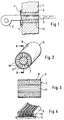
- FIG. 1 shows the part of a furnace wall (1) of a furnace, on the outside of which a gas burner (2) is attached.
- the combustion chamber wall (1) has a continuous, cylindrical recess (3) which is delimited on the outside by a flange (4) on which the gas burner (2) is suspended.
- a cylindrical fiber burner block (5) is inserted into the recess (3).
- the fiber burner block (5) serves to guide a flame (6) generated by the gas burner (2) and isolates this flame (6) from the combustion chamber wall (1).
- Figures (2) and (3) show the structure of the fiber burner block (5) shown in Figure (1) in more detail.
- the fiber burner block (5) consists of a fiber sheath (7) and an outer sheath (8) of metal, for example expanded metal.
- the fiber jacket (7) is composed of fiber strips arranged next to one another in the circumferential direction and alternately rectangular in cross section - denoted by (9) for example - and triangular fiber strips - denoted by (10 ⁇ ) by way of example , the latter tapering towards the guide channel (11) enveloped by the fiber jacket (7).
- the fiber strips (9, 10 ⁇ ) extend over the entire axial length of the fiber jacket (7). They are dimensioned in such a way that they lie under tension on the inside of the outer casing (8). This also results in mutual printing of the fiber strips (9, 10 ⁇ ) with one another.
- Figure (4) shows a part of the fiber jacket (7) with the rectangular fiber strips (9) and the triangular fiber strips (10 ⁇ ) which is laid out horizontally on a base (12). It is made clear that the individual fibers extend in planes that lie essentially parallel to the surfaces with which the fiber strips (9, 10 ⁇ ) lie against one another after completion of the fiber jacket (7). This results in a brush-like structure with fibers projecting perpendicular to the surfaces both on the outside and on the inside of the fiber jacket (7).
- the channel (14) enveloped by it is conical with a cross section tapering towards the end of the channel (14).
- the fiber cladding (15) of the fiber burner block (13) is also conical and is encased on the outside by a conical outer cladding (16) which is not shown in detail.
- the fiber burner block (13) is inserted into an air duct (17), which is also tapered and is closed at the tapered end and runs parallel and at a distance from the outer casing (16).
- a flame is generated in the channel (14) from the widened end, which creates a negative pressure due to the nozzle effect of the fiber jacket (15), so that air from the outside via the air channel (17) via the through openings in the outer jacket (16) and is sucked into the channel (14) via the fiber jacket (15).
- this improves the combustion and, on the other hand, the fiber jacket (15) is constantly cooled.
- the fiber cladding (15) is composed of alternately rectangular cross-section of fiber strips - designated by (18) for example - and triangular cross-sections of fiber strip - designated by (19).
- fiber strips (18, 19) are shortened at regular intervals towards the tapering end of the channel (11) and, moreover, they are designed in a wedge shape.
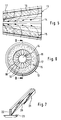
- Figures (7) and (8) show at their ends wedge-shaped cut fiber strips (20 incident) and additionally shortened fiber strips (21) next to a rectangular fiber strip (22), in Figure (7) placed on a flat surface (23) side by side and in Figure (8) in individual representation both from the side and from the front. With the help of such fiber strips (20 ⁇ , 21, 22), the desired cone angle for the fiber burner block (13) can be realized.
- FIG. 9 shows a cylindrical fiber burner (24).
- this fiber burner block (24) has a fiber cladding (25) which is composed of annular fiber disks arranged one behind the other in the axial direction - for example designated (26).
- the fiber discs (26) are punched out of a fiber mat of appropriate thickness, the fibers extending primarily in planes parallel to the surfaces of the fiber mat.
- the main course of the fibers in the fiber burner block (24) lies in radial planes, so that here too there is a brush-shaped structure on the inside and outside surface of the fiber jacket (25).
- a tensioning device which has two tension anchors (27, 28) extending in the axial direction, the ends of the tension anchors (27, 28) being open support on one side on annular or cross-shaped support disks (29, 30 ⁇ ) and on the other end on a rigid support ring (31).
- tension anchors (27, 28) can be easily adjust the contact pressure of the fiber discs (26) with each other and thus also the porosity of the fiber jacket (25), and even subsequently.
- a burner (32) is partially shown in FIG. It has a feed channel (33) for the fuel mixture, at the end of which a cylindrical fiber burner block (34) connects downwards.
- the fiber burner block (34) has a fiber jacket (35), which is composed of annular fiber disks arranged one behind the other in the axial direction - designated by (36) for example.
- the fiber jacket (35) envelops a guide channel (37) which adjoins the feed channel (33) in the axial direction and is closed at the end by a clamping plate (38).
- the guide channel (37) is penetrated by a tension anchor (39) connected to the tensioning plate (38), which is screwed in the area of the mouth of the feed channel (33) to a bracket, not shown, and with which the mutual contact pressure of the fiber disks (36) and allow the porosity of the fiber jacket (35) to be adjusted.
- a flame (40 ⁇ ) is generated on the outer peripheral surface of the fiber jacket (35).
- a fuel-air mixture is introduced into the guide channel (37) via the feed channel (33). Due to its porosity, the fuel-air mixture flows through the fiber jacket (35), then emerges on the outer circumferential surface and is ignited or ignites there itself.
- Figure (12) shows another burner (41) with a rectangular feed channel (42) for a fuel-air mixture.
- the feed channel (42) has a widening (43) with lateral clamping flanges (44, 45) which run parallel to one another.
- a fiberboard (46) is clamped, which consists of a large number of side by side arranged, cross-sectionally rectangular fiber strips (47).
- the fiber strips (47) are dimensioned such that they abut one another and on the clamping flanges (44, 45) in compression.
- one of the clamping flanges (44, 45) can be made adjustable in the plane of the fiberboard (46) in order to change the preload and thus the porosity of the fiberboard (46).
- the fiber strips (47) are arranged in such a way that the fibers extend in planes which lie in the flow direction. This results in a brush-like structure on the free surfaces of the fiber mats (46).
- a fuel-air mixture is passed through the fiber plate (46) via the feed channel (42).
- the mixture then emerges from the upper outside of the fiberboard (46) and is ignited there, so that a large-area flame (48) is produced.
- FIG. It has an air supply duct (50 ⁇ ), which has a funnel-shaped extension (51) towards the bottom.
- the air supply duct (50) is coaxially penetrated by a fuel duct (52) which opens into a distributor (53) on the underside.
- a funnel-shaped fiberboard (54) is clamped in the extension (51). Its conical top is at a distance from the wall of the extension (51).
- the fiberboard (54) is penetrated by the fuel channel (52), the openings of the distributor (53) being directed towards the underside of the fiberboard (54).
- the fiberboard (54) consists of a multiplicity of fibrous strips - denoted by (55) for example - their mutual contact surfaces extending in the axial direction. This also applies to the planes in which the fibers of the individual fiber strips (55) run, so that there is a brush-like shape on the top and bottom of the fiber plate (54) Structure results.
- the fiberboard (54) is supplied with pure air via the air supply duct (50 ⁇ ) and the extension (51). This penetrates the fiberboard (54) and then emerges finely distributed on the underside. At the same time, fuel is distributed via the fuel channel (52) and the distributor (53) over the underside of the fiberboard (54), which mixes in this area with the air exiting from the fiberboard (54) and in this way results in an ignitable mixture.
Landscapes
- Engineering & Computer Science (AREA)
- Chemical & Material Sciences (AREA)
- Combustion & Propulsion (AREA)
- Mechanical Engineering (AREA)
- General Engineering & Computer Science (AREA)
- Gas Burners (AREA)
- Yarns And Mechanical Finishing Of Yarns Or Ropes (AREA)
- Paper (AREA)
- Manufacture, Treatment Of Glass Fibers (AREA)
- Inorganic Fibers (AREA)
Claims (25)
- Brique de brûleur en fibres (5, 13, 24, 34) comprenant un élément constitutif (7, 15, 25, 35, 46, 54) en fibres réfractaires, dans laquelle l'élément constitutif en fibres (7, 15, 25, 35, 46, 54) est assemblé à partir de bandes en fibres individuelles (9, 10, 18, 19, 20, 21, 26, 36, 47, 55), cependant que les bandes en fibres (9, 10, 18, 19, 20, 21, 26, 36, 47, 55) sont maintenues en appui sous pression mutuel par un dispositif de serrage (8, 16, 27, 28, 29, 30, 31, 38, 39, 44, 45, 51), caractérisée par le fait que les bandes en fibres (9, 10, 18, 19, 20, 21, 26, 36, 47, 55) sont constituées chacune par des fibres qui sont mobiles les unes par rapport aux autres et dont la cohésion n'est assurée que par elles-mêmes, et que les dimensions en section transversale des bandes en fibres (9, 10, 18, 19, 20, 21, 26, 36, 47, 55) sont telles que la masse volumique apparente de l'élément constitutif en fibres (7, 15, 25, 35, 46, 54) soit pour l'essentiel la même sur toute sa section transversale.
- Brique de brûleur en fibres selon la revendication 1, caractérisée par le fait que les bandes en fibres (9, 10, 18, 19, 20, 21, 26, 36, 47, 55) sont comprimées au préalable individuellement ou par groupes.
- Brique de brûleur en fibres selon la revendication 1 ou 2, caractérisée par le fait que l'élément constitutif en fibres est constitué par une enveloppe en fibres (7, 15, 25, 35) qui entoure un canal (11, 14, 37).
- Brique de brûleur en fibres selon la revendication 3, caractérisée par le fait qu'une pluralité de bandes en fibres (9, 10, 18, 19, 20, 21) qui s'étendent pour le reste dans la direction axiale sont disposées les unes à côté des autres dans la direction de la périphérie.
- Brique de brûleur en fibres selon la revendication 4, caractérisée par le fait que les bandes en fibres (10, 19) présentent une section transversale qui se rétrécit dans la direction du côté intérieur de l'enveloppe en fibres.
- Brique de brûleur en fibres selon la revendication 4, caractérisée par le fait que la section transversale présente la forme d'un trapèze ou la forme d'un triangle.
- Brique de brûleur en fibres selon la revendication 5, caractérisée par le fait que des bandes en fibres à section transversale rectangulaire (9, 18, 20, 21) alternent dans la direction de la périphérie de l'enveloppe en fibres (7, 15) avec des bandes en fibres (10, 19) dont la section transversale se rétrécit dans la direction du canal.
- Brique de brûleur en fibres selon l'une des revendications 4 à 7, caractérisée par le fait que le canal (14) se rétrécit dans la direction d'une extrémité de l'enveloppe en fibres (15), et par le fait que les bandes en fibres (21) sont partiellement raccourcies dans la direction de cette extrémité.
- Brique de brûleur en fibres selon l'une des revendications 4 à 8, caractérisée par le fait que le canal (14) se rétrécit dans la direction d'une extrémité de l'enveloppe en fibres (15), et par le fait que les bandes en fibres (20) se rétrécissent en forme de coin en section transversale, du moins partiellement, dans la direction de cette ouverture.
- Brique de brûleur en fibres selon l'une des revendications 3 à 9, caractérisée par le fait que des bandes en fibres alternent dans la direction de la périphérie de l'enveloppe en fibres avec des bandes insérées constituées par un matériau isolant indéformable.
- Brique de brûleur en fibres selon l'une des revendications 3 à 10, caractérisée par le fait que le dispositif de serrage est réalisé sous la forme d'une chemise extérieure (8, 16) sur le côté intérieur de laquelle l'enveloppe en fibres (7, 15) porte avec une compression préalable.
- Brique de brûleur en fibres selon la revendication 11, caractérisée par le fait que la chemise extérieure (16) est pourvue d'une pluralité d'ouvertures de passage.
- Brique de brûleur en fibres selon la revendication 11 ou 12, caractérisée par le fait que la chemise extérieure est entourée extérieurement par un matelas de fibres réfractaires.
- Brique de brûleur en fibres selon la revendication 3, caractérisée par le fait que les bandes en fibres sont réalisées sous la forme de disques en fibres annulaires (26, 36) qui sont disposés les uns derrière les autres dans la direction du canal (37).
- Brique de brûleur en fibres selon la revendication 14, caractérisée par le fait que le dispositif de serrage comporte des disques d'extrémité (29, 30, 31) et des tirants (27, 28) qui les relient et qui s'étendent dans la direction axiale.
- Brique de brûleur en fibres selon l'une des revendications 3 à 15, caractérisée par le fait que les bandes en fibres (9, 10, 18, 19, 20, 21, 26, 36) présentent une contexture des fibres qui s'étend préférentiellement dans des plans radiaux.
- Brique de brûleur en fibres selon l'une des revendications 3 à 16, caractérisée par le fait que le canal (37) est fermé à une extrémité.
- Brique de brûleur en fibres selon la revendication 1 ou 2, caractérisée par le fait que l'élément constitutif en fibres est réalisé sous la forme d'une plaque en fibres (46, 54) qui est composée de bandes en fibres (47, 55).
- Brique de brûleur en fibres selon la revendication 18, caractérisée par le fait que la plaque en fibres (46) est plane.
- Brique de brûleur en fibres selon la revendication 18, caractérisée par le fait que la plaque en fibres (54) est en forme d'entonnoir.
- Brique de brûleur en fibres selon l'une des revendications 18 à 20, caractérisée par le fait que les fibres de la plaque en fibres (46, 54) s'étendent préférentiellement dans des plans qui sont transversaux par rapport au plan de la plaque.
- Brûleur comprenant une brique de brûleur en fibres (5) pourvue d'une enveloppe en fibres (7) selon l'une des revendications 3 à 17, caractérisé par le fait que l'enveloppe en fibres (7) est introduite dans un évidement (3) du four qui constitue le dispositif de serrage.
- Brûleur comprenant une brique de brûleur en fibres (13) pourvue d'une enveloppe en fibres (15) selon l'une des revendications 3 à 17, caractérisé par le fait que l'enveloppe en fibres (15) est introduite dans un canal à air (17) à distance des parois de celui-ci.
- Brûleur comprenant une brique de brûleur en fibres (34) pourvue d'un élément constitutif en fibres (35, 46, 54) selon l'une des revendications 3 à 21, caractérisé par le fait que l'élément constitutif en fibres (35, 46, 54) est disposé à l'extrémité d'un canal d'amenée (33, 42, 50, 52) qui est destiné au mélange combustible.
- Brûleur selon la revendication 24, caractérisé par le fait que le canal d'amenée est divisé en un canal à combustible (52) et en un canal à air (50), cependant que le canal à combustible (52) débouche d'une manière centrale sur le côté extérieur de l'élément constitutif en fibres (54), tandis que l'élément constitutif en fibres (54) est disposé à l'extrémité du canal à air (50).
Applications Claiming Priority (2)
| Application Number | Priority Date | Filing Date | Title |
|---|---|---|---|
| AT2205/90 | 1990-11-02 | ||
| AT0220590A AT394768B (de) | 1990-11-02 | 1990-11-02 | Brennerflammenfuehrungsteil |
Publications (3)
| Publication Number | Publication Date |
|---|---|
| EP0483743A2 EP0483743A2 (fr) | 1992-05-06 |
| EP0483743A3 EP0483743A3 (en) | 1992-10-28 |
| EP0483743B1 true EP0483743B1 (fr) | 1996-07-10 |
Family
ID=3529956
Family Applications (1)
| Application Number | Title | Priority Date | Filing Date |
|---|---|---|---|
| EP91118382A Expired - Lifetime EP0483743B1 (fr) | 1990-11-02 | 1991-10-29 | Brique réfractaire en fibre et brûleur avec une telle brique réfractaire en fibre |
Country Status (5)
| Country | Link |
|---|---|
| US (1) | US5348468A (fr) |
| EP (1) | EP0483743B1 (fr) |
| JP (1) | JPH0539918A (fr) |
| AT (2) | AT394768B (fr) |
| DE (2) | DE9113418U1 (fr) |
Families Citing this family (11)
| Publication number | Priority date | Publication date | Assignee | Title |
|---|---|---|---|---|
| EP0622587A3 (fr) * | 1992-04-30 | 1995-04-05 | Poretti Gaggini Sa | Procédé de combustion pour brûler des gaz et chambre de combustion pour réaliser le procédé. |
| US5961316A (en) * | 1995-10-25 | 1999-10-05 | Weil-Mclain | Oil burner |
| US6435861B1 (en) * | 1997-06-10 | 2002-08-20 | Usf Filtration And Separations Group, Inc. | Gas burner assembly and method of making |
| DE10233340B4 (de) * | 2002-07-23 | 2004-07-15 | Rational Ag | Porenbrenner sowie Gargerät, enthaltend mindestens einen Porenbrenner |
| JP5210925B2 (ja) * | 2009-02-27 | 2013-06-12 | 三菱重工業株式会社 | 燃料タンクの発火防止構造 |
| US10174945B2 (en) * | 2013-10-14 | 2019-01-08 | Bloom Engineering Company, Inc. | Burner port block assembly |
| US9175909B2 (en) | 2014-02-07 | 2015-11-03 | Temtek Solutions, Inc. | Refractory insulating module |
| JP6062873B2 (ja) * | 2014-02-12 | 2017-01-18 | 中外炉工業株式会社 | 炉体構造 |
| WO2015122281A1 (fr) * | 2014-02-12 | 2015-08-20 | 三菱樹脂株式会社 | Carreau de brûleur, brûleur, et four |
| US11428438B2 (en) * | 2020-04-28 | 2022-08-30 | Rheem Manufacturing Company | Carryover burners for fluid heating systems and methods thereof |
| JP7267330B2 (ja) * | 2021-02-18 | 2023-05-01 | マフテック株式会社 | リジェネバーナ用耐火物ユニット及びその製造方法 |
Family Cites Families (23)
| Publication number | Priority date | Publication date | Assignee | Title |
|---|---|---|---|---|
| US3425675A (en) * | 1966-12-14 | 1969-02-04 | Alco Standard Corp | Burner tube assembly for heat treating furnace |
| DE1930312A1 (de) * | 1969-06-14 | 1970-12-17 | Schwank Gmbh | Mit Gas oder fluessigem Brennstoff betriebener Infrarotstrahler |
| FR2086625A5 (fr) * | 1970-04-03 | 1971-12-31 | Produits Refractaires | |
| US3918255A (en) * | 1973-07-06 | 1975-11-11 | Westinghouse Electric Corp | Ceramic-lined combustion chamber and means for support of a liner with combustion air penetrations |
| DE2714835A1 (de) * | 1976-04-07 | 1977-10-20 | Thomas M Smith | Gasbefeuerte strahlungsheizvorrichtungen |
| US4220132A (en) * | 1978-12-13 | 1980-09-02 | The Barber Manufacturing Company | Gas-fired radiant burner |
| GB2039829B (en) * | 1979-01-10 | 1983-09-01 | Isolite Babcock Refractories | Insulating block |
| DE2922083C2 (de) * | 1979-05-31 | 1984-02-09 | Hoch-Temperatur-Technik Gmbh, 4900 Herford | Flammrohr für eine brennerbefeuerte Feuerungsanlage |
| DE3005257A1 (de) * | 1980-02-13 | 1981-10-01 | Didier-Werke Ag, 6200 Wiesbaden | Brennermuffelstein |
| DE3048044C2 (de) * | 1980-12-19 | 1983-06-09 | Helmut Dipl.-Chem. 8000 München Ulrich | Flammrohr aus hitzebeständigem Werkstoff für Brenner, insbesondere Ölbrenner |
| JPS59501993A (ja) * | 1982-11-11 | 1984-11-29 | モ−ガン・サ−ミツク・リミテツド | 自己通風型熱放射ガス・バーナ組立体 |
| SE8207507D0 (sv) * | 1982-12-30 | 1982-12-30 | Bulten Kanthal Ab | Flamskold |
| US4630594A (en) * | 1983-03-09 | 1986-12-23 | Ellersick Russell R | Furnace wall lining composition and the use thereof |
| FR2558243B1 (fr) * | 1984-01-13 | 1987-01-30 | Lorraine Laminage | Piece de four constituant un passage pour des gaz sortant d'un bruleur et procede d'obtention |
| CA1241910A (fr) * | 1984-02-16 | 1988-09-13 | Dirk N. Granberg | Bruleur a energie rayonnante |
| FR2589555B1 (fr) * | 1985-11-06 | 1989-11-10 | Gaz De France | Bruleur a gaz a air souffle |
| US4643667A (en) * | 1985-11-21 | 1987-02-17 | Institute Of Gas Technology | Non-catalytic porous-phase combustor |
| US4746287A (en) * | 1986-01-17 | 1988-05-24 | Gas Research Institute | Fiber matrix burner composition with aluminum alloys and method of formulation |
| ATA149287A (de) * | 1987-06-12 | 1988-11-15 | Vaillant Gmbh | Vormischgasbrenner |
| DE3833169A1 (de) * | 1987-09-30 | 1989-04-13 | Vaillant Joh Gmbh & Co | Brenner, insbesondere gasbrenner |
| EP0321611A1 (fr) * | 1987-12-22 | 1989-06-28 | Franco Andreoli | Tube foyer pour tube chauffant à radiation pour four industriel |
| DE3926699A1 (de) * | 1989-08-12 | 1991-02-14 | Kloeckner Waermetechnik | Gasbrenner |
| ATA20062001A (de) * | 2001-12-20 | 2005-10-15 | Steba Brandschutztore Ges M B | Verriegelungseinrichtung für eine tür |
-
1990
- 1990-11-02 AT AT0220590A patent/AT394768B/de not_active IP Right Cessation
-
1991
- 1991-10-29 DE DE9113418U patent/DE9113418U1/de not_active Expired - Lifetime
- 1991-10-29 EP EP91118382A patent/EP0483743B1/fr not_active Expired - Lifetime
- 1991-10-29 DE DE59107991T patent/DE59107991D1/de not_active Expired - Fee Related
- 1991-10-29 AT AT91118382T patent/ATE140311T1/de not_active IP Right Cessation
- 1991-11-01 JP JP3288134A patent/JPH0539918A/ja not_active Withdrawn
- 1991-11-04 US US07/787,079 patent/US5348468A/en not_active Expired - Fee Related
Also Published As
| Publication number | Publication date |
|---|---|
| EP0483743A3 (en) | 1992-10-28 |
| ATA220590A (de) | 1991-11-15 |
| EP0483743A2 (fr) | 1992-05-06 |
| ATE140311T1 (de) | 1996-07-15 |
| DE9113418U1 (de) | 1991-12-12 |
| AT394768B (de) | 1992-06-25 |
| JPH0539918A (ja) | 1993-02-19 |
| DE59107991D1 (de) | 1996-08-14 |
| US5348468A (en) | 1994-09-20 |
Similar Documents
| Publication | Publication Date | Title |
|---|---|---|
| DE60007608T2 (de) | Brenner und verfahren zum betrieb einer gasturbine | |
| DE69011005T2 (de) | Keramischer Gasbrenner für Heisslufterhitzer und Steine dafür. | |
| EP0483743B1 (fr) | Brique réfractaire en fibre et brûleur avec une telle brique réfractaire en fibre | |
| DE2635623C2 (fr) | ||
| DE69006406T2 (de) | Brennerstein-Aufbau. | |
| WO1995003511A1 (fr) | Support de combustion ceramique pour bruleurs radiants en surface et son procede de fabrication | |
| EP2066878B1 (fr) | Élément filtrant, notamment pour filtrer les gaz d'échappement d'un moteur à combustion interne | |
| EP0093472A1 (fr) | Brique creuse prismatique en matériaux réfractaires pour l'empilage des chambres d'un four de verrerie | |
| EP0330161B1 (fr) | Procédé de fabrication d'u filtre de particules de suie | |
| DE4025479A1 (de) | Keramikfasern verwendender industrieofen | |
| DE1905148C3 (de) | Strahlungsbrenner | |
| DE2809521C2 (de) | Keramischer Brenner | |
| DE4433154A1 (de) | Feuerfester Wandstein für einen Heizkanal eines offenen Ringkammerofens | |
| EP0427828B1 (fr) | Chambre de chauffage dans des fours a coke et procede de chauffage | |
| DE3811477C2 (fr) | ||
| EP0470945B1 (fr) | Elément de construction pour cheminées, système de cheminées multiples ainsi que procédé de fabrication d'un élément de construction pour cheminées | |
| DE3537976C1 (en) | Filter device for soot particle filtration | |
| DE202010000357U1 (de) | Wärmespeicherelement | |
| EP0711954B1 (fr) | Cheminée d'air/fumée | |
| DE1262491B (de) | Brennereinrichtung zur Beheizung turmartiger Regenerativ-Gas- oder Winderhitzer | |
| EP3870898A1 (fr) | Barreau de grille pour grille à gradins | |
| DE3727937A1 (de) | Waermeisolierung von gleit-, trag- oder querrohren einer industriellen feuerungsanlage | |
| DE1529197C (de) | Strahlungsbrenner | |
| EP0875718A1 (fr) | Brûleur à gaz | |
| DE3107348C2 (de) | Gasverteilvorrichtung für ein Wirbelbett |
Legal Events
| Date | Code | Title | Description |
|---|---|---|---|
| PUAI | Public reference made under article 153(3) epc to a published international application that has entered the european phase |
Free format text: ORIGINAL CODE: 0009012 |
|
| AK | Designated contracting states |
Kind code of ref document: A2 Designated state(s): AT BE CH DE DK ES FR GB GR IT LI LU NL SE |
|
| PUAL | Search report despatched |
Free format text: ORIGINAL CODE: 0009013 |
|
| AK | Designated contracting states |
Kind code of ref document: A3 Designated state(s): AT BE CH DE DK ES FR GB GR IT LI LU NL SE |
|
| 17P | Request for examination filed |
Effective date: 19930308 |
|
| 17Q | First examination report despatched |
Effective date: 19940304 |
|
| GRAG | Despatch of communication of intention to grant |
Free format text: ORIGINAL CODE: EPIDOS AGRA |
|
| GRAH | Despatch of communication of intention to grant a patent |
Free format text: ORIGINAL CODE: EPIDOS IGRA |
|
| GRAH | Despatch of communication of intention to grant a patent |
Free format text: ORIGINAL CODE: EPIDOS IGRA |
|
| GRAA | (expected) grant |
Free format text: ORIGINAL CODE: 0009210 |
|
| AK | Designated contracting states |
Kind code of ref document: B1 Designated state(s): AT BE CH DE DK ES FR GB GR IT LI LU NL SE |
|
| PG25 | Lapsed in a contracting state [announced via postgrant information from national office to epo] |
Ref country code: IT Free format text: LAPSE BECAUSE OF FAILURE TO SUBMIT A TRANSLATION OF THE DESCRIPTION OR TO PAY THE FEE WITHIN THE PRE;WARNING: LAPSES OF ITALIAN PATENTS WITH EFFECTIVE DATE BEFORE 2007 MAY HAVE OCCURRED AT ANY TIME BEFORE 2007. THE CORRECT EFFECTIVE DATE MAY BE DIFFERENT FROM THE ONE RECORDED.SCRIBED TIME-LIMIT Effective date: 19960710 Ref country code: DK Effective date: 19960710 Ref country code: GR Free format text: LAPSE BECAUSE OF FAILURE TO SUBMIT A TRANSLATION OF THE DESCRIPTION OR TO PAY THE FEE WITHIN THE PRESCRIBED TIME-LIMIT Effective date: 19960710 Ref country code: ES Free format text: THE PATENT HAS BEEN ANNULLED BY A DECISION OF A NATIONAL AUTHORITY Effective date: 19960710 Ref country code: NL Free format text: LAPSE BECAUSE OF FAILURE TO SUBMIT A TRANSLATION OF THE DESCRIPTION OR TO PAY THE FEE WITHIN THE PRESCRIBED TIME-LIMIT Effective date: 19960710 |
|
| REF | Corresponds to: |
Ref document number: 140311 Country of ref document: AT Date of ref document: 19960715 Kind code of ref document: T |
|
| REF | Corresponds to: |
Ref document number: 59107991 Country of ref document: DE Date of ref document: 19960814 |
|
| GBT | Gb: translation of ep patent filed (gb section 77(6)(a)/1977) |
Effective date: 19960820 |
|
| ET | Fr: translation filed | ||
| PG25 | Lapsed in a contracting state [announced via postgrant information from national office to epo] |
Ref country code: SE Effective date: 19961010 |
|
| NLV1 | Nl: lapsed or annulled due to failure to fulfill the requirements of art. 29p and 29m of the patents act | ||
| PLBE | No opposition filed within time limit |
Free format text: ORIGINAL CODE: 0009261 |
|
| STAA | Information on the status of an ep patent application or granted ep patent |
Free format text: STATUS: NO OPPOSITION FILED WITHIN TIME LIMIT |
|
| 26N | No opposition filed | ||
| PGFP | Annual fee paid to national office [announced via postgrant information from national office to epo] |
Ref country code: GB Payment date: 19970807 Year of fee payment: 7 |
|
| PGFP | Annual fee paid to national office [announced via postgrant information from national office to epo] |
Ref country code: FR Payment date: 19970818 Year of fee payment: 7 |
|
| PGFP | Annual fee paid to national office [announced via postgrant information from national office to epo] |
Ref country code: AT Payment date: 19971021 Year of fee payment: 7 Ref country code: BE Payment date: 19971021 Year of fee payment: 7 |
|
| PGFP | Annual fee paid to national office [announced via postgrant information from national office to epo] |
Ref country code: CH Payment date: 19971022 Year of fee payment: 7 |
|
| PGFP | Annual fee paid to national office [announced via postgrant information from national office to epo] |
Ref country code: DE Payment date: 19971029 Year of fee payment: 7 |
|
| PGFP | Annual fee paid to national office [announced via postgrant information from national office to epo] |
Ref country code: LU Payment date: 19980210 Year of fee payment: 7 |
|
| PG25 | Lapsed in a contracting state [announced via postgrant information from national office to epo] |
Ref country code: GB Free format text: LAPSE BECAUSE OF NON-PAYMENT OF DUE FEES Effective date: 19981029 Ref country code: LU Free format text: LAPSE BECAUSE OF NON-PAYMENT OF DUE FEES Effective date: 19981029 Ref country code: AT Free format text: LAPSE BECAUSE OF NON-PAYMENT OF DUE FEES Effective date: 19981029 |
|
| PG25 | Lapsed in a contracting state [announced via postgrant information from national office to epo] |
Ref country code: LI Free format text: LAPSE BECAUSE OF NON-PAYMENT OF DUE FEES Effective date: 19981031 Ref country code: BE Free format text: LAPSE BECAUSE OF NON-PAYMENT OF DUE FEES Effective date: 19981031 Ref country code: CH Free format text: LAPSE BECAUSE OF NON-PAYMENT OF DUE FEES Effective date: 19981031 |
|
| BERE | Be: lapsed |
Owner name: CHAMOTTEWAREN- UND THONOFENFABRIK AUG. RATH JUN. Effective date: 19981031 |
|
| REG | Reference to a national code |
Ref country code: CH Ref legal event code: PL |
|
| GBPC | Gb: european patent ceased through non-payment of renewal fee |
Effective date: 19981029 |
|
| PG25 | Lapsed in a contracting state [announced via postgrant information from national office to epo] |
Ref country code: FR Free format text: LAPSE BECAUSE OF NON-PAYMENT OF DUE FEES Effective date: 19990630 |
|
| REG | Reference to a national code |
Ref country code: FR Ref legal event code: ST |
|
| PG25 | Lapsed in a contracting state [announced via postgrant information from national office to epo] |
Ref country code: DE Free format text: LAPSE BECAUSE OF NON-PAYMENT OF DUE FEES Effective date: 19990803 |