EP0483806A1 - Tragsäule - Google Patents
Tragsäule Download PDFInfo
- Publication number
- EP0483806A1 EP0483806A1 EP91118528A EP91118528A EP0483806A1 EP 0483806 A1 EP0483806 A1 EP 0483806A1 EP 91118528 A EP91118528 A EP 91118528A EP 91118528 A EP91118528 A EP 91118528A EP 0483806 A1 EP0483806 A1 EP 0483806A1
- Authority
- EP
- European Patent Office
- Prior art keywords
- base tube
- device component
- set forth
- respect
- unit
- Prior art date
- Legal status (The legal status is an assumption and is not a legal conclusion. Google has not performed a legal analysis and makes no representation as to the accuracy of the status listed.)
- Granted
Links
- 238000004873 anchoring Methods 0.000 claims description 18
- 239000000463 material Substances 0.000 claims description 3
- 239000004033 plastic Substances 0.000 claims description 3
- 229920003023 plastic Polymers 0.000 claims description 3
- 239000006223 plastic coating Substances 0.000 description 4
- 230000000694 effects Effects 0.000 description 3
- 230000004323 axial length Effects 0.000 description 1
- 230000000295 complement effect Effects 0.000 description 1
- 238000010276 construction Methods 0.000 description 1
- 230000002542 deteriorative effect Effects 0.000 description 1
- 230000005484 gravity Effects 0.000 description 1
- 230000000284 resting effect Effects 0.000 description 1
- 238000005096 rolling process Methods 0.000 description 1
Images

Classifications
-
- F—MECHANICAL ENGINEERING; LIGHTING; HEATING; WEAPONS; BLASTING
- F16—ENGINEERING ELEMENTS AND UNITS; GENERAL MEASURES FOR PRODUCING AND MAINTAINING EFFECTIVE FUNCTIONING OF MACHINES OR INSTALLATIONS; THERMAL INSULATION IN GENERAL
- F16F—SPRINGS; SHOCK-ABSORBERS; MEANS FOR DAMPING VIBRATION
- F16F9/00—Springs, vibration-dampers, shock-absorbers, or similarly-constructed movement-dampers using a fluid or the equivalent as damping medium
- F16F9/02—Springs, vibration-dampers, shock-absorbers, or similarly-constructed movement-dampers using a fluid or the equivalent as damping medium using gas only or vacuum
- F16F9/0209—Telescopic
- F16F9/0245—Means for adjusting the length of, or for locking, the spring or dampers
-
- A—HUMAN NECESSITIES
- A47—FURNITURE; DOMESTIC ARTICLES OR APPLIANCES; COFFEE MILLS; SPICE MILLS; SUCTION CLEANERS IN GENERAL
- A47C—CHAIRS; SOFAS; BEDS
- A47C3/00—Chairs characterised by structural features; Chairs or stools with rotatable or vertically-adjustable seats
- A47C3/20—Chairs or stools with vertically-adjustable seats
- A47C3/30—Chairs or stools with vertically-adjustable seats with vertically-acting fluid cylinder
Definitions
- chair columns comprise a base tube connectable with a base frame, which base frame is provided with rollers rolling on a floor.
- a gas spring is provided within the base tube.
- the gas spring comprises a cylinder and a piston rod.
- the piston rod is provided with a piston within the cylinder.
- the cylinder is filled with a pressurized gas on both sides of the piston .
- a bypass interconnects the chambers within the cylinder on both sides of the piston.
- a locking valve is allocated to the bypass. When the locking valve is open, the piston rod is pushed out of the cylinder by the pressurized gas acting onto the cross-section of the piston rod.
- the piston rod By an axial load, the piston rod can be pushed inwards of the cylinder against the pressure of the pressurized gas acting onto the cross-sectional area of the piston rod. By closing the locking valve, the relative position of the cylinder and the piston rod can be locked in any desired relative position.
- the piston rod is supported on a base plate of the stand tube by an axial load transmitting ball bearing, such as to be rotatable with respect to the stand tube.
- the cylinder of the gas spring is guided within a guide sleeve inserted into the upper end of the stand tube.
- the cylinder is slidable and rotatable with respect to the guide sleeve.
- the upper end of the cylinder is provided with a conical fastening section.
- a seat carrier having a complementary conical hole can be fixed on this conical fastening section.
- a locking control pin extends through the upper end of the cylinder for opening and closing the bypass.
- the lower end of the piston rod is laterally movable with respect to the base plate.
- a limited upward movement of the cylinder with respect to the base plate is allowed, such that the stroke of height adjustment is limited.
- a base tube is again fastened to a chair base.
- An inner telescopic tube is guided within the stand tube.
- the inner telescopic tube is closed at its upper end, and a seat plate is fastened to the closed upper end.
- a gas spring is housed within the base tube and the telescopic tube.
- the cylinder of the gas spring is rigidly fastened by its bottom to a bottom wall of the stand tube.
- the piston rod of the gas spring carries at its upper end a rope pulley.
- a rope is guided from the base plate of the stand tube around this pulley to the lower end of the inner telescopic tube.
- Locking means are provided for locking the movement of the telescopic innertube with respect to the stand tube.
- the cylinder, the piston rod and the pulley have no lateral engagement with the telescopic tube.
- the pulley On upward movement of the piston rod with respect to the cylinder, the pulley is lifted and the inner telescopic tube is also lifted.
- the lifting velocity of the inner telescopic tube is greater than the lifting velocity of the piston rod.
- the stroke of the inner telescopic tube is larger than the stroke of the piston rod.
- a further object of the invention is to allow a perfect rotation of a seat member or the like with respect to the base tube.
- a further object of the invention is to provide a column unit which allows a locking element to be provided at the upper end of the column unit.
- a further object of the invention is to provide a simple and operationally reliable and compact design.
- a column unit comprises a base tube having a base tube axis, a first base tube end and a second base tube end. Guiding means are inserted into the base tube adjacent the second base tube end.
- a positioning device having a device axis substantially coinciding with the base tube axis is accommodated within the base tube.
- This positioning device has a first device component unit and a second device component unit.
- the first and the second device component units are axially movable with respect to each other and are substantially lockable with respect to each other in a plurality of relative axial positions.
- the first device component unit is axially supported by device support means and rotatable with respect thereto.
- the second device component unit extends beyond the second base tube end and the guiding means.
- An outer portion of the second device component unit extends beyond the second base tube end and the guiding means and is adapted for connection with a column-guided part.
- the second device component unit is in axially sliding guiding engagement with the guiding means.
- the guiding means are axially slidingly guided along the base tube with respect to the second base tube end in response to relative axial movement of the first and second device component units, such as to be moved axially outwards of the base tube with respect to the second base tube end in response to axially outward movement of the second device component unit out of the base tube with respect to the second base tube end, and to be axially moved inwards into the base tube with respect to the second base tube end in response to axially inward movement of the second device component unit into the base tube with respect to the second base tube end.
- the maximum stroke of the positioning device can be increased without deteriorating the guiding function between the stand tube and the second device component unit, because the guiding means follow the axial movement of the second device component unit.
- the guiding means are entrainable with the second device component unit in at least one axial direction of movement by frictional engagement of the second device component unit and the guiding means, or the guiding means are entrainable by the second device component unit in at least one axial direction by abutment means.
- gravity forces may be used for moving the guiding means in downward direction.
- the second device component unit may be provided with a first abutment ring, which is accommodated within a radial inner annular recess of a guiding sleeve.
- This annular recess has a substantially axially directed end face.
- the first abutment ring is engageable with this end face for entraining the guiding sleeve in a direction outwards of the base tube with respect to the second end of the base tube.
- the second device component unit may be provided with a second abutment member engageable with the guiding means for entraining said guiding means inwards of the base tube with respect to the second base tube end.
- This second abutment member may be provided by a column-guided part, e. g. a chair plate, fastened to the second device component unit.
- the guiding means may be centered within the base tube by a centering tube.
- the centering tube may be fixed against rotation about the base tube axis with respect to the base tube.
- the guiding means may be fixed against rotation with respect to the base tube.
- the base tube may be provided with a stop face limiting inward movement of the guiding means inwards of the base tube.
- the guiding means may be at least partially made of a plastics material, e. g. in the form of a guiding sleeve.
- the device support means may be provided inside the base tube.
- the second device component unit may be provided at an axial end thereof remote from the device support means with locking control means.
- the device support means may be axially fixed with respect to the base tube. This is particularly true for those possible embodiments of the invention in which the guiding means are moved by the second device component unit through friction means or abutment means.
- the device support means may be axially movable with respect to the base tube. More particularly, the device support means may be axially movable with respect to the base tube in response to relative axial movement of the first and the second device component units.
- the axial movement of the device support means may be controlled in response to relative axial movement of the first and second device component units through tackle means.
- tackle means one has to understand a combination of at least one flexible tension member and a pulley.
- the device support means may be movable with respect to the base tube against elastic resistance in response to axial load on the positioning device. Such, a certain spring effect of a seat plate may be obtained.
- a very simple and reliable embodiment with axially movable device support means may be obtained, if the axial movement of the device support means is controlled in response to relative axial movement of the first and the second device component units by at least one flexible tension member running from a first anchoring point of the second device component unit via at least one pulley mounted on the device support means towards a second anchoring point on the base tube, said guiding means being axially movable together with said device support means.
- the outward movement of the second device component unit with respect to the base tube corresponds to 1.5 times the extension movement of the positioning device
- the outward movement of the guiding means corresponds to 0.5 times the extension movement of the positioning device.
- the positioning device may be rotatable about the base tube axis with respect to the device support means and with respect to the tackle means. More particularly, the first anchoring point may be rotatable with respect to the second device component unit about the base tube axis.
- a plurality of flexible tension members may be provided. It is also possible that a common tension member follows a plurality of paths between said second device component unit, said device support means and said base tube.
- the tackle means may comprise at least one elastically stretchable, flexible tension member. So, the device support means are movable in response to axial load against elastic resistance. A similar effect may be obtained in that the tackle means comprise a flexible tension member having at least one end axially fixed to an elastically displaceable anchoring point.
- the positioning device may comprise a cylinder piston device and more particularly a gas spring having a piston rod member and a cylinder member.
- the first device component unit may comprise the piston rod member
- the second device component unit may comprise the cylinder member.
- the first device component unit may comprise the cylinder member
- the second device component unit may comprise a guide tube axially fixed with respect to the piston rod member and guided within the guiding means.
- a column unit comprises a base tube having a base tube axis, a first base tube end and a second base tube end.
- a positioning device having a device axis substantially coinciding with the base tube axis is inserted into the base tube.
- This positioning device has a first device component unit and a second device component unit. Said first and said second device component units are axially movable with respect to each other and are substantially lockable with respect to each other in a plurality of relative axial positions.
- the first device component unit is axially supported by device support means.
- the second device component unit extends beyond the second base tube end. An outer portion of the second device component unit extending beyond the second base tube end is adapted for connection with a column-guided part.
- the device support means are axially movable with respect to the base tube in response to relative axial movement of the first and second device component units. More particularly, the axial movement of said device support means may be controlled in response to relative axial movement of the first and second device component units through tackle means.
- the axial support means may be movable with respect to the base tube against elastic resistance in response to axial load on the positioning device.
- the axial movement of said device support means may be controlled in response to relative axial movement of the first and the second device component units by at least one flexible tension member running from a first anchoring point on said second device component unit via at least one pulley mounted on said device support means towards a second anchoring point on said base tube.
- axial outward movement of the second device component unit amounts to 1.5 times the axial extension of the positioning device.
- the positioning device may be rotatable about the base tube axis with respect to the device support means and with respect to the tackle means.
- the positioning device may comprise a cylinder piston device having a piston rod member and a cylinder member.
- the first device component unit may comprise the piston rod member
- the second device component unit may comprise the cylinder member.
- the first device component unit may comprise the cylinder member
- the second device component unit may comprise the piston rod member.
- the cylinder piston device is e. g. a gas spring.
- the column units of the present invention are particularly useful as vertical chair columns.
- gas springs of the type as shown in US-PS 4,848,524 are used.
- a particular advantage is that the stroke of the gas spring may substantially correspond to the total length of the respective cylinder.
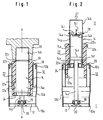
- a base tube is designated by 10.
- This base tube has an axis A-A, a first end 10a and a second end 10b.
- a support plate 12 is fastened inside the base tube 10.
- a gas spring 14 is accommodated within the base tube 10.
- the gas spring 14 comprises a cylinder 14a with a conical fastening section 14b for fastening a seat carrier 16 thereon.
- a piston rod 14c is sealingly guided through the lower end portion of the cylinder 14a.
- the piston rod 14c is connected with a piston 14d inside the cylinder 14a.
- the piston 14d separates within the cylinder 14a two working chambers 14e and 14f from each other. Both working chambers 14e and 14f are filled with a pressurized gas.
- the working chambers 14e and 14f are interconnected by an annular bypass channel 14g via openings 14h and 14i.
- the bypass channel 14g can be opened and closed by a control valve member 14k through a control pin 14l.
- the piston rod 14c is by its lower end supported through an axial ball bearing 18 on the support plate 12. The lower end of the piston rod 14c is capable of limited lateral movement along arrow 20 with respect to the support plate 12.
- the cylinder 14a is guided by a guiding sleeve 22.
- This guiding sleeve 22 is centered by a centering tube 26.
- the centering tube 26 is non-rotatably mounted within the base tube 10, and the guiding sleeve 22 is non-rotatably but axially movably guided within the centering tube 26.
- the cylinder 14a is axially and rotatably guided in the guiding sleeve 22.
- An abutment ring 24 is fixed to the lower end of the cylinder 14a. This abutment ring 24 is accommodated within an annular recess 22a of the guiding sleeve 22.
- the guiding sleeve 22 is provided with a stop flange 22b at the upper end thereof for axial engagement with the centering tube 26.
- the cylinder 14a is provided with a further abutment ring 28 for engagement with an upper end face 22c of the guiding sleeve 22.
- the column unit is in the lowest possible position.
- the axial position of the guiding sleeve 22 is defined by the stop flange 22b being located between the upper end of the centering tube 26 and the further abutment ring 28.
- the guiding sleeve 22 On downward movement of the cylinder 14a, the guiding sleeve 22 may be entrained by frictional force downwards as long as the frictional force between the cylinder 14a and the guiding sleeve 22 is greater than the frictional force between the guiding sleeve 22 and the centering tube 26. If this is not true, the guiding sleeve 22 is moved downward anyway as soon as the further abutment ring 28 engages the upper end face 22c of the guiding sleeve 22.
- the guiding sleeve 22 can be injection-molded from plastics material.
- the lower end of the stand tube 10 is provided with a conical section 10d for engagement with a conical hole of a chair base.
- the support plate 112 is axially floating within the base tube 110.
- the guiding sleeve 122 is resting on the support plate 112.
- a plastic coating 122g is provided on the inner side of the guiding sleeve 122.
- a plurality of tackles 132 are provided.
- a tackle 132 comprises a rope or wire 132a, which runs from an anchoring hook 132b provided on the cylinder 114a downwards and via two pulleys 132c to an anchoring point 132d provided on the base tube 110.
- the ropes 132a may be elastically stretchable so that the gas spring 114 is movable downwards against elastic resistance and provides a spring effect for a seat plate.
- the support plate 112 and the guiding sleeve 122 are moved upwards by a length unit 1/2.
- the guiding sleeve 122 is again telescoped outwards for improving the guiding function between the cylinder 114a and the base tube 110 in the higher range of positions.
- the support plate 112 and the guiding sleeve 122 are moved downwards again.
- the downward movement of the guiding sleeve 122 may be due to a positive connection of the guiding sleeve 122 with the support plate 112 or may be effected through friction of the cylinder 11a with the plastic coating 122g on the inner surface of the guiding sleeve 122.
- the anchoring hook 132b may be provided on a ring member 132g which is rotatable with respect to the cylinder 114a so that rotation of the gas spring 114 is posible with respect to the base tube 110 without twisting the tackles 132.
- the support plate 112 may be non-rotatably guided with respect to the base tube 110.
- the ropes 132a remain tensioned under all conditions. The elasticity of the ropes 132a allows elastic downward movement of the gas spring 114 under an axial load F.
- ropes 132a may also provide an axially elastic mounting for the anchoring points 132d or 132b.
- the gas spring 114 may have the same design as shown in Fig. 2.
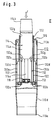
- the gas spring of Fig. 4 is different from the gas spring in Figs. 1 to 3 and is designated by 238.
- This gas spring comprises a cylinder 238a.
- a piston rod 238c extends through the upper end of the cylinder 238a.
- a piston 238d is fastened to the piston rod 238c inside the cylinder 238a and separates two working chambers 238e and 238f from each other.
- the working chambers 238e and 238f are interconnectable by a bore 238g through the piston 238d.
- the bore 238g can be opened and closed through a valve plate 238k, which is actuatable through an actuating rod 238l extending through a bore of the piston rod 238c.
- the actuating rod 238l is controlled by a control lever 238m rotatably mounted on the seat carrier 216.
- a guide tube 240 is fastened to the piston rod 238c at 240a.
- the guide tube 240 is provided with a conical section 240b adapted to the seat carrier 216.
- the guide tube 240 may be slidably guided on the cylinder 238a.
- the guide tube 240 is axially guided on the inside of the guiding sleeve 222 through a plastic coating 222g of the guiding sleeve 222.
- the guiding sleeve 222 is guided on the inside of the base tube 210 through a plastic coating 210f.
- the lower end of the cylinder 238a is supported by the support plate 212 through the ball bearing 218.
- the support plate 212 may be connected with the guide tube 240.
- a tackle 232 is provided by a flexible rope 232a running from an anchoring point 232b on the guide tube 240 via a pulley 232c provided on the support plate 212 to a further anchoring point 232d provided on the base tube 210.
Landscapes
- Engineering & Computer Science (AREA)
- General Engineering & Computer Science (AREA)
- Mechanical Engineering (AREA)
- Chairs Characterized By Structure (AREA)
- Fluid-Damping Devices (AREA)
Applications Claiming Priority (2)
| Application Number | Priority Date | Filing Date | Title |
|---|---|---|---|
| DE4034633 | 1990-10-31 | ||
| DE4034633A DE4034633A1 (de) | 1990-10-31 | 1990-10-31 | Gasfeder zur hoehenverstellung |
Publications (2)
| Publication Number | Publication Date |
|---|---|
| EP0483806A1 true EP0483806A1 (de) | 1992-05-06 |
| EP0483806B1 EP0483806B1 (de) | 1995-04-12 |
Family
ID=6417383
Family Applications (1)
| Application Number | Title | Priority Date | Filing Date |
|---|---|---|---|
| EP91118528A Expired - Lifetime EP0483806B1 (de) | 1990-10-31 | 1991-10-30 | Tragsäule |
Country Status (6)
| Country | Link |
|---|---|
| US (1) | US5377942A (de) |
| EP (1) | EP0483806B1 (de) |
| JP (1) | JP3711149B2 (de) |
| AU (1) | AU647198B2 (de) |
| DE (2) | DE4034633A1 (de) |
| ES (1) | ES2074627T3 (de) |
Cited By (6)
| Publication number | Priority date | Publication date | Assignee | Title |
|---|---|---|---|---|
| US5234187A (en) * | 1992-06-02 | 1993-08-10 | Steelcase Inc. | Chair height adjustment mechanism |
| EP0566045A1 (de) * | 1992-04-11 | 1993-10-20 | Stabilus GmbH | Säuleneinheit, insbesondere Stuhlsäuleneinheit |
| US5397111A (en) * | 1992-10-30 | 1995-03-14 | Stabilus Gmbh | Actuating device in combination with a lockable cylinder piston unit |
| US5608960A (en) * | 1995-06-07 | 1997-03-11 | Herman Miller, Inc. | Apparatus and method for mounting a support column to a chair base and tilt control housing |
| US5740997A (en) * | 1995-06-07 | 1998-04-21 | Herman Miller, Inc. | Pneumatic height adjustment column for a chair |
| US5765804A (en) * | 1992-06-15 | 1998-06-16 | Herman Miller, Inc. | Pneumatic support colunm for a chair |
Families Citing this family (15)
| Publication number | Priority date | Publication date | Assignee | Title |
|---|---|---|---|---|
| DE4200786A1 (de) * | 1992-01-14 | 1993-07-15 | Suspa Compart Ag | Laengenverstellbare saeule fuer tische, stuehle o. dgl. |
| ES1028821Y (es) * | 1994-08-08 | 1995-08-16 | Talleres Gain S Coop R L | Dispositivo de premontaje en cilindro a gas. |
| WO1998003360A1 (en) * | 1996-07-24 | 1998-01-29 | Pilot Precision Dampers Limited | Extended travel damper |
| DE19715892C2 (de) * | 1997-04-16 | 2000-11-30 | Stabilus Gmbh | Höhenverstellbare Säule mit Tiefenfederung |
| DE19717531C2 (de) * | 1997-04-25 | 1999-02-25 | Stabilus Gmbh | Höhenverstellbare Säule mit einer Übertragungseinrichtung |
| US5979845A (en) * | 1997-05-16 | 1999-11-09 | Steelcase Inc. | Hub tube/washer assembly |
| US6244609B1 (en) * | 1998-07-28 | 2001-06-12 | Jeff Wilson | Front wheel suspension fork for two wheeled vehicles and method |
| US7134634B2 (en) * | 2001-02-15 | 2006-11-14 | Samhongsa Co., Ltd. | Column unit |
| KR100477072B1 (ko) * | 2002-10-16 | 2005-03-17 | 주식회사 삼홍사 | 칼럼 유니트 |
| DE102004034220B3 (de) * | 2004-07-14 | 2006-02-23 | Stabilus Gmbh | Objektträgersäule |
| AT502943B1 (de) * | 2005-04-01 | 2011-07-15 | Blum Gmbh Julius | Dämpfvorrichtung für bewegbare möbelteile |
| US20070102979A1 (en) * | 2005-10-25 | 2007-05-10 | GLOBAL TOTAL OFFICE an Ontario limited partnership having GLOBAL UPHOLSTERY CO. | Adjustment mechanism for a chair and method for replacing a telescoping cylinder in a reconfigurable chair |
| DE102006011491B3 (de) * | 2006-03-14 | 2007-10-11 | Stabilus Gmbh | Höhenverstellbare Stuhlsäule |
| CN103561612B (zh) * | 2011-04-29 | 2016-10-12 | 株式会社三弘社 | 椅用支柱单元 |
| US9961421B2 (en) * | 2016-05-30 | 2018-05-01 | Gao Fong Yi Industrial Co., Ltd. | Microphone stand adjusting structure |
Citations (4)
| Publication number | Priority date | Publication date | Assignee | Title |
|---|---|---|---|---|
| CH523675A (de) * | 1970-04-17 | 1972-06-15 | Helfenstein & Bucher | Vorrichtung an Möbel zur Höhenverstellung eines Möbelteils |
| DE1529723B2 (de) * | 1966-12-02 | 1977-03-10 | Stabilus Gmbh, 5400 Koblenz | Federbein fuer hoehenverstellbare moebelteile |
| DE2816761A1 (de) * | 1978-04-18 | 1979-10-31 | Fritz R Stolberg | Pneumatische feder |
| DE3604397A1 (de) * | 1985-05-06 | 1986-11-06 | Fichtel & Sachs Industries, Inc., Colmar, Pa. | Laengeneinstellbare tragsaeule |
Family Cites Families (10)
| Publication number | Priority date | Publication date | Assignee | Title |
|---|---|---|---|---|
| DE426360C (de) * | 1924-12-18 | 1926-03-16 | Fritz Haas Maschinen Und App F | Operationsstuhl oder -tisch mit teleskopartig verstellbarer Vorrichtung zur Hoeheneinstellung der Sitz- oder Tischflaeche |
| DE621149C (de) * | 1934-03-15 | 1935-11-02 | August Froescher Jun | Fernrohrartig verschiebbare Zylinderfuehrung an Fluessigkeitshebevorrichtungen fuer Friseur- und Operationsgestuehl |
| GB1410983A (en) * | 1971-12-23 | 1975-10-22 | Stabilus Ind Handels Gmbh | Column assembly combination |
| DE2603488C3 (de) * | 1976-01-30 | 1979-02-22 | Dornier System Gmbh, 7990 Friedrichshafen | Teleskopartig längenveränderliche Einrichtung, insbesondere Auslegertragarm o.dgl., z.B. für ferngesteuerte Einrichtungen, insbesondere für die Raumfahrttechnik |
| DE3420528A1 (de) * | 1984-06-01 | 1985-12-05 | Stabilus Gmbh, 5400 Koblenz | Stufenlos verstellbare hubvorrichtung |
| DE3517003A1 (de) * | 1985-05-10 | 1986-11-13 | Stabilus Gmbh, 5400 Koblenz | Konusverbindung an einer hoehenverstellbaren stuhl- oder tischsaeule |
| DE3833959A1 (de) * | 1988-10-06 | 1990-04-12 | Bauer Fritz & Soehne Ohg | Laengenverstellbare saeule fuer stuehle, tische oder dergleichen |
| DE4031105C2 (de) * | 1990-10-02 | 2000-03-09 | High Tech Geraetebau | Teleskopartig ausfahrbare Hubsäule, insbesondere zur Höhenverstellung einer Kamera |
| DE4207470A1 (de) * | 1991-05-01 | 1992-11-05 | Suspa Compart Ag | Blockierbare hubvorrichtung zum stufenlosen verstellen von stuhlsitzen |
| US5234187A (en) * | 1992-06-02 | 1993-08-10 | Steelcase Inc. | Chair height adjustment mechanism |
-
1990
- 1990-10-31 DE DE4034633A patent/DE4034633A1/de not_active Withdrawn
-
1991
- 1991-10-30 ES ES91118528T patent/ES2074627T3/es not_active Expired - Lifetime
- 1991-10-30 DE DE69108847T patent/DE69108847T2/de not_active Expired - Lifetime
- 1991-10-30 EP EP91118528A patent/EP0483806B1/de not_active Expired - Lifetime
- 1991-10-30 AU AU86914/91A patent/AU647198B2/en not_active Ceased
- 1991-10-30 JP JP28460591A patent/JP3711149B2/ja not_active Expired - Fee Related
-
1994
- 1994-05-10 US US08/240,605 patent/US5377942A/en not_active Expired - Lifetime
Patent Citations (4)
| Publication number | Priority date | Publication date | Assignee | Title |
|---|---|---|---|---|
| DE1529723B2 (de) * | 1966-12-02 | 1977-03-10 | Stabilus Gmbh, 5400 Koblenz | Federbein fuer hoehenverstellbare moebelteile |
| CH523675A (de) * | 1970-04-17 | 1972-06-15 | Helfenstein & Bucher | Vorrichtung an Möbel zur Höhenverstellung eines Möbelteils |
| DE2816761A1 (de) * | 1978-04-18 | 1979-10-31 | Fritz R Stolberg | Pneumatische feder |
| DE3604397A1 (de) * | 1985-05-06 | 1986-11-06 | Fichtel & Sachs Industries, Inc., Colmar, Pa. | Laengeneinstellbare tragsaeule |
Cited By (8)
| Publication number | Priority date | Publication date | Assignee | Title |
|---|---|---|---|---|
| EP0566045A1 (de) * | 1992-04-11 | 1993-10-20 | Stabilus GmbH | Säuleneinheit, insbesondere Stuhlsäuleneinheit |
| US5497966A (en) * | 1992-04-11 | 1996-03-12 | Stabilus Gmbh | Column unit, in particular a chair column unit |
| US5234187A (en) * | 1992-06-02 | 1993-08-10 | Steelcase Inc. | Chair height adjustment mechanism |
| US5765804A (en) * | 1992-06-15 | 1998-06-16 | Herman Miller, Inc. | Pneumatic support colunm for a chair |
| EP0856270A3 (de) * | 1992-06-15 | 2000-08-30 | Herman Miller, Inc. | Tragsäule für einen Stuhl |
| US5397111A (en) * | 1992-10-30 | 1995-03-14 | Stabilus Gmbh | Actuating device in combination with a lockable cylinder piston unit |
| US5608960A (en) * | 1995-06-07 | 1997-03-11 | Herman Miller, Inc. | Apparatus and method for mounting a support column to a chair base and tilt control housing |
| US5740997A (en) * | 1995-06-07 | 1998-04-21 | Herman Miller, Inc. | Pneumatic height adjustment column for a chair |
Also Published As
| Publication number | Publication date |
|---|---|
| US5377942A (en) | 1995-01-03 |
| ES2074627T3 (es) | 1995-09-16 |
| AU647198B2 (en) | 1994-03-17 |
| AU8691491A (en) | 1992-05-07 |
| DE69108847T2 (de) | 1995-08-24 |
| DE4034633A1 (de) | 1992-05-07 |
| EP0483806B1 (de) | 1995-04-12 |
| JP3711149B2 (ja) | 2005-10-26 |
| JPH04263807A (ja) | 1992-09-18 |
| DE69108847D1 (de) | 1995-05-18 |
Similar Documents
| Publication | Publication Date | Title |
|---|---|---|
| EP0483806B1 (de) | Tragsäule | |
| US7108339B2 (en) | Self-closing drawer guides with integrated damping | |
| US4383595A (en) | Gas spring having three different damping-rate stages | |
| US4166612A (en) | Gas spring with means for impeding piston movement away from one terminal position | |
| US5856862A (en) | Boom camera crane | |
| US4796871A (en) | Gas spring with end position damping | |
| EP0768476B1 (de) | Gasfeder | |
| EP0381188B1 (de) | Hydraulisch blockierbare Gasfeder | |
| US20040242383A1 (en) | Strength and power training system | |
| US5507070A (en) | Mechanism for closing a lid | |
| JPS6021257B2 (ja) | 2つの相対運動可能な構造部分とガスばねとから成る構造体 | |
| GB2159237A (en) | A cylinder piston device | |
| KR100786818B1 (ko) | 회전 제어 클러치를 갖는 가스실린더 | |
| US4284178A (en) | Hydraulic shock absorber | |
| EP4115092B1 (de) | Pneumatische teleskopische säulenanordnung | |
| WO2018088906A1 (en) | Telescopic ladder assembly | |
| US5579607A (en) | Convenient automatic closing system for doors | |
| WO1996003602A1 (en) | A chock valve for a vacuum lifting device | |
| US4076201A (en) | Adjustable chair-spindle assembly | |
| US3828694A (en) | Adjustment- and arresting mechanism especially for a drafting table | |
| CA2244252A1 (en) | Large standing umbrella | |
| US20050156366A1 (en) | Arrangement with a height-adjustable component | |
| US5772184A (en) | Load support mounted control arrangement for fluid pressure operated hoist | |
| US4438910A (en) | Shock absorbing snubber for derrick hooks | |
| KR200311408Y1 (ko) | 자전거 안장의 높이조절장치 |
Legal Events
| Date | Code | Title | Description |
|---|---|---|---|
| PUAI | Public reference made under article 153(3) epc to a published international application that has entered the european phase |
Free format text: ORIGINAL CODE: 0009012 |
|
| AK | Designated contracting states |
Kind code of ref document: A1 Designated state(s): DE ES FR GB IT |
|
| 17P | Request for examination filed |
Effective date: 19920518 |
|
| 17Q | First examination report despatched |
Effective date: 19940325 |
|
| GRAA | (expected) grant |
Free format text: ORIGINAL CODE: 0009210 |
|
| AK | Designated contracting states |
Kind code of ref document: B1 Designated state(s): DE ES FR GB IT |
|
| REF | Corresponds to: |
Ref document number: 69108847 Country of ref document: DE Date of ref document: 19950518 |
|
| ITF | It: translation for a ep patent filed | ||
| ET | Fr: translation filed | ||
| REG | Reference to a national code |
Ref country code: ES Ref legal event code: FG2A Ref document number: 2074627 Country of ref document: ES Kind code of ref document: T3 |
|
| PLBE | No opposition filed within time limit |
Free format text: ORIGINAL CODE: 0009261 |
|
| STAA | Information on the status of an ep patent application or granted ep patent |
Free format text: STATUS: NO OPPOSITION FILED WITHIN TIME LIMIT |
|
| 26N | No opposition filed | ||
| REG | Reference to a national code |
Ref country code: GB Ref legal event code: IF02 |
|
| PGFP | Annual fee paid to national office [announced via postgrant information from national office to epo] |
Ref country code: ES Payment date: 20061030 Year of fee payment: 16 |
|
| PGFP | Annual fee paid to national office [announced via postgrant information from national office to epo] |
Ref country code: IT Payment date: 20061031 Year of fee payment: 16 |
|
| REG | Reference to a national code |
Ref country code: FR Ref legal event code: ST Effective date: 20080630 |
|
| PGFP | Annual fee paid to national office [announced via postgrant information from national office to epo] |
Ref country code: FR Payment date: 20061016 Year of fee payment: 16 |
|
| REG | Reference to a national code |
Ref country code: ES Ref legal event code: FD2A Effective date: 20071031 |
|
| PG25 | Lapsed in a contracting state [announced via postgrant information from national office to epo] |
Ref country code: FR Free format text: LAPSE BECAUSE OF NON-PAYMENT OF DUE FEES Effective date: 20071031 Ref country code: ES Free format text: LAPSE BECAUSE OF NON-PAYMENT OF DUE FEES Effective date: 20071031 |
|
| PGFP | Annual fee paid to national office [announced via postgrant information from national office to epo] |
Ref country code: GB Payment date: 20081021 Year of fee payment: 18 |
|
| PG25 | Lapsed in a contracting state [announced via postgrant information from national office to epo] |
Ref country code: IT Free format text: LAPSE BECAUSE OF NON-PAYMENT OF DUE FEES Effective date: 20071030 |
|
| PG25 | Lapsed in a contracting state [announced via postgrant information from national office to epo] |
Ref country code: GB Free format text: LAPSE BECAUSE OF NON-PAYMENT OF DUE FEES Effective date: 20091030 |
|
| PGFP | Annual fee paid to national office [announced via postgrant information from national office to epo] |
Ref country code: DE Payment date: 20101031 Year of fee payment: 20 |
|
| REG | Reference to a national code |
Ref country code: DE Ref legal event code: R071 Ref document number: 69108847 Country of ref document: DE |
|
| REG | Reference to a national code |
Ref country code: DE Ref legal event code: R071 Ref document number: 69108847 Country of ref document: DE |
|
| PG25 | Lapsed in a contracting state [announced via postgrant information from national office to epo] |
Ref country code: DE Free format text: LAPSE BECAUSE OF EXPIRATION OF PROTECTION Effective date: 20111031 |