EP0483885A1 - Vibrateur pour béton ou similaire - Google Patents
Vibrateur pour béton ou similaire Download PDFInfo
- Publication number
- EP0483885A1 EP0483885A1 EP91118827A EP91118827A EP0483885A1 EP 0483885 A1 EP0483885 A1 EP 0483885A1 EP 91118827 A EP91118827 A EP 91118827A EP 91118827 A EP91118827 A EP 91118827A EP 0483885 A1 EP0483885 A1 EP 0483885A1
- Authority
- EP
- European Patent Office
- Prior art keywords
- disks
- vibrator according
- housing
- vibrator
- end covers
- Prior art date
- Legal status (The legal status is an assumption and is not a legal conclusion. Google has not performed a legal analysis and makes no representation as to the accuracy of the status listed.)
- Granted
Links
- 238000003698 laser cutting Methods 0.000 claims abstract description 8
- 239000002184 metal Substances 0.000 claims abstract description 4
- 238000009415 formwork Methods 0.000 claims description 6
- 239000000463 material Substances 0.000 claims description 3
- 238000004804 winding Methods 0.000 claims description 2
- 238000013461 design Methods 0.000 abstract description 7
- 238000009416 shuttering Methods 0.000 abstract 1
- 238000013459 approach Methods 0.000 description 6
- 238000004519 manufacturing process Methods 0.000 description 4
- 238000010276 construction Methods 0.000 description 2
- 239000012528 membrane Substances 0.000 description 2
- 230000002349 favourable effect Effects 0.000 description 1
- 238000009434 installation Methods 0.000 description 1
- 238000003754 machining Methods 0.000 description 1
- 238000000034 method Methods 0.000 description 1
- 238000012545 processing Methods 0.000 description 1
- 125000006850 spacer group Chemical group 0.000 description 1
- 238000012549 training Methods 0.000 description 1
- 238000009827 uniform distribution Methods 0.000 description 1
- 238000009423 ventilation Methods 0.000 description 1
Images


Classifications
-
- E—FIXED CONSTRUCTIONS
- E04—BUILDING
- E04G—SCAFFOLDING; FORMS; SHUTTERING; BUILDING IMPLEMENTS OR AIDS, OR THEIR USE; HANDLING BUILDING MATERIALS ON THE SITE; REPAIRING, BREAKING-UP OR OTHER WORK ON EXISTING BUILDINGS
- E04G21/00—Preparing, conveying, or working-up building materials or building elements in situ; Other devices or measures for constructional work
- E04G21/02—Conveying or working-up concrete or similar masses able to be heaped or cast
- E04G21/06—Solidifying concrete, e.g. by application of vacuum before hardening
- E04G21/063—Solidifying concrete, e.g. by application of vacuum before hardening making use of vibrating or jolting tools
- E04G21/065—Solidifying concrete, e.g. by application of vacuum before hardening making use of vibrating or jolting tools acting upon the shuttering
Definitions
- the invention relates to a vibrator for concrete or the like, in particular for mounting on formwork, with a housing with a cylindrical interior and two end caps, and an imbalance rotating in the housing.
- Vibrators of the aforementioned type are known.
- the two end covers are connected to a cast housing that can be machined on all major surfaces.
- the end covers have a fixed axle.
- This axis carries a tube, the inside diameter of which is larger than the outside diameter of the axis and which represents the eccentrically rotating unbalance.
- the unbalance is driven by compressed air, which passes through a membrane into the interior of the unbalance tube is introduced and discharged through an outlet on the opposite side.
- the invention is based on the vibrators of the type specified. According to the invention it is proposed that the housing consists of individual, superimposed ring disks made of sheet metal.
- ring disks can be manufactured in different ways. For example, they can be punched. However, the invention prefers that the ring disks are made from plates by means of laser cutting.
- the construction of the housing from annular disks according to the invention offers a significant simplification. Depending on the size of the desired housing, more or fewer ring washers can be put together. It is not necessary to specially process the washers, especially if they are produced by laser cutting. With the specified design, the inner surface of the housing is not a running surface for the unbalance, which is guided by the central axis.
- the annular disks have round holes distributed uniformly on the circumference Pick up fasteners. These round holes are made in the same operation as the panes themselves.
- the round holes accommodate, for example, bolts that extend between the end caps.
- the desired size of the housing can easily be obtained in this way by adding or omitting washers.
- a particular advantage of this design is that the end covers can be installed in different positions relative to the ring washers, ie relative to the housing. In this way, the position of the central axis for the unbalance can also be changed. This has the advantage that the supply of compressed air can be adjusted depending on the type of use of the vibrator, so that it is always ensured that the vibrator also starts up. With the previous design, it was necessary to align the axis with the end covers accordingly.
- the invention further proposes that a plurality of ring disks of substantially the same shape are combined with ring disks which have contours on the outer circumference which serve to fasten the housing to a base frame and / or to a formwork.
- the fastening means for the housing can be produced in the same way as the ring disks themselves.
- Part of the ring disks can, for example, have foot-like projections which serve to connect the relevant ring disks and thus also the vibrator to a base frame or formwork .
- the contours are also produced by laser cutting, so that their manufacturing effort is greatly reduced.
- end covers are also made from plate by means of laser cutting. If flat plates made of tempered sheet metal are used, arrangements can easily be obtained which no longer require subsequent processing.
- the washers that form the housing in the invention generally have the same thickness. However, it is also possible to insert one or more spacer rings between the ring disks or the ring disks and the end covers in order to achieve a certain housing length with sufficient accuracy.
- the invention proposes recesses in the end caps that deviate from the circular shape and that carry the central axes for the unbalance.
- the ends of the central axis are adapted to these recesses. In this way, the mutual position of the central axis and the end cover is determined.
- the orientation of the central axis with respect to the respective purpose is obtained by twisting the end cover in relation to the ring washers. This alignment is important for the startup behavior.
- the end covers can in particular consist of several disks, which are also each made by laser cutting. By assembling the end cover from several disks, the designs required for the correct functioning can be easily achieved without the need for complex machining processes.
- the design according to the invention is not only applicable to vibrators that are driven by compressed air.
- the design according to the invention can also be realized in the case of electric vibrators.
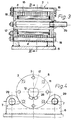
- the housing 1 consists of a package of ring disks 2, some of which have the same shape, but which also differ from one another in particular with regard to their outer contour 5.
- the end covers 8 and 9 each consist of two disks 13 and 14.
- the disks 13 and 14 or the end covers 8 and 9 serve on the one hand to seal the interior 15, which is enclosed by the annular disks 2, and on the other hand also to guide the tubular unbalance 16 and the fixation and non-rotatable fixing of the central axis 12.
- the disks 13 and 14 have recesses 11 which deviate from the circular shape, as shown in the illustrations 4 and 6 emerge.
- a flattening 17 is provided on the central axis 12.
- Both the washers 2 and the washers 13 and 14 of the end caps 8 and 9 have uniformly distributed round holes 3, in which the connecting elements 4 designed as screws are arranged.
- the associated nuts are designated 18 and the screw heads 19.
- the uniform distribution of the round holes 3 allows the end caps 8 and 9, and thus also the central axis 12, to be arranged in different ways in the intended division of, for example, 45 degrees, in order to select the correct position of the central axis 12 with respect to the respective installation.
- part of the ring disks 2 is designed as a simple disk, while other ring disks, namely the ring disks 32 have foot-like projections 7, so that an outer contour 5 deviating from the circular shape is obtained.
- other approaches 21 are provided.
- the foot-like lugs 7 engage under the mounting bolts 20 of the base frame 6.
- the lugs 21 interact with the clamping wedge 23, which is also supported on the base frame 6 by means of the tab 22. In this way, a stable fixing of the housing 1 with respect to the base frame 6 can be obtained.
- On the base frame 6 there are also support surfaces 24 for the housing 1.
- the central axis 12 has the connection 25 for the compressed air which flows into the interior of the unbalance 16 via the membrane 26. This training is known per se. The air finally reaches the outlet openings 28 via the ventilation bores 27.
- a suitable number of distance compensation rings 10 can also be used, which are made of thinner material than the washers 2.
- FIG. 4 differs from that of FIGS. 1 to 3 essentially in that a part of the washers 2 each have two foot-like lugs 7 which cooperate with circular wedges 29 on the base frame 6.
- the exemplary embodiment according to FIGS. 5 and 6 partly has ring disks whose foot-like approaches 7 are designed in such a way that pressure plates 30 can be placed on these foot-like approaches.
- These pressure plates 30 have screw openings 31, for example, through which screws can be inserted.
- the washers 2 with the foot-like approaches 7 and washers 2 without such approaches are combined in such a way that the fastening screws in the screw openings 31 are not hindered, so that a vibrator of this type can be screwed directly onto a formwork.
Landscapes
- Engineering & Computer Science (AREA)
- Architecture (AREA)
- Mechanical Engineering (AREA)
- Civil Engineering (AREA)
- Structural Engineering (AREA)
- Apparatuses For Generation Of Mechanical Vibrations (AREA)
Applications Claiming Priority (2)
| Application Number | Priority Date | Filing Date | Title |
|---|---|---|---|
| DE9015077U DE9015077U1 (de) | 1990-11-02 | 1990-11-02 | Rüttler für Beton o.dgl. |
| DE9015077U | 1990-11-02 |
Publications (2)
| Publication Number | Publication Date |
|---|---|
| EP0483885A1 true EP0483885A1 (fr) | 1992-05-06 |
| EP0483885B1 EP0483885B1 (fr) | 1995-08-09 |
Family
ID=6858955
Family Applications (1)
| Application Number | Title | Priority Date | Filing Date |
|---|---|---|---|
| EP91118827A Expired - Lifetime EP0483885B1 (fr) | 1990-11-02 | 1991-11-04 | Vibrateur pour béton ou similaire |
Country Status (2)
| Country | Link |
|---|---|
| EP (1) | EP0483885B1 (fr) |
| DE (2) | DE9015077U1 (fr) |
Cited By (1)
| Publication number | Priority date | Publication date | Assignee | Title |
|---|---|---|---|---|
| FR2715424A1 (fr) * | 1994-01-21 | 1995-07-28 | Quille Entreprise | Procédé et dispositif pour contrôler la mise en Óoeuvre du béton dans un train de banches. |
Citations (3)
| Publication number | Priority date | Publication date | Assignee | Title |
|---|---|---|---|---|
| FR749490A (fr) * | 1933-07-24 | |||
| FR844060A (fr) * | 1937-09-30 | 1939-07-18 | Bosch Gmbh Robert | Appareil pour le vibrage intérieur du béton et autres matériaux semblables |
| US4172986A (en) * | 1978-04-21 | 1979-10-30 | Okura Electric Industry Company, Ltd. | Vibrator |
-
1990
- 1990-11-02 DE DE9015077U patent/DE9015077U1/de not_active Expired - Lifetime
-
1991
- 1991-11-04 DE DE59106213T patent/DE59106213D1/de not_active Expired - Fee Related
- 1991-11-04 EP EP91118827A patent/EP0483885B1/fr not_active Expired - Lifetime
Patent Citations (3)
| Publication number | Priority date | Publication date | Assignee | Title |
|---|---|---|---|---|
| FR749490A (fr) * | 1933-07-24 | |||
| FR844060A (fr) * | 1937-09-30 | 1939-07-18 | Bosch Gmbh Robert | Appareil pour le vibrage intérieur du béton et autres matériaux semblables |
| US4172986A (en) * | 1978-04-21 | 1979-10-30 | Okura Electric Industry Company, Ltd. | Vibrator |
Non-Patent Citations (1)
| Title |
|---|
| US-A-4 172 986 * |
Cited By (1)
| Publication number | Priority date | Publication date | Assignee | Title |
|---|---|---|---|---|
| FR2715424A1 (fr) * | 1994-01-21 | 1995-07-28 | Quille Entreprise | Procédé et dispositif pour contrôler la mise en Óoeuvre du béton dans un train de banches. |
Also Published As
| Publication number | Publication date |
|---|---|
| DE59106213D1 (de) | 1995-09-14 |
| EP0483885B1 (fr) | 1995-08-09 |
| DE9015077U1 (de) | 1992-03-12 |
Similar Documents
| Publication | Publication Date | Title |
|---|---|---|
| EP0104458B1 (fr) | Tamis pour centrifuge et procédé de fabrication dudit tamis | |
| EP0081813A1 (fr) | Jeu de disques en particulier sous forme d'un outil pour un appareil à travailler le sol | |
| DE3804728A1 (de) | Stator einer elektrischen drehenden maschine | |
| EP0133320A2 (fr) | Tête porte-lame pour machine à tailler les roues dentées | |
| DE69513276T2 (de) | Siebplatte für die Papierherstellung | |
| DE2836395C2 (de) | Satzfräser | |
| DE3238951A1 (de) | Kraftaufnehmer | |
| DE2119389C3 (de) | Baukastensystem für den Aufbau beliebiger Ständeranordnungen von Walzenmaschinen, insbesondere Kalandern | |
| DE7033660U (de) | Pressenstaender. | |
| EP0245668A2 (fr) | Accouplement d'arbres à haute élasticité | |
| EP0483885B1 (fr) | Vibrateur pour béton ou similaire | |
| DE69507243T2 (de) | Reinigungssieb insbesondere für Papierfaserbrei | |
| EP0649924B1 (fr) | Dispositif de sectionnement de fils d'une broche d'un métier à filer ou à retordre à anneaux | |
| DE3604963A1 (de) | Einsatz zum unterteilen einer giessform | |
| EP1036622B1 (fr) | Dispositif pour couper par rupture | |
| DE2410437A1 (de) | Vertikale elektrische maschine, insbesondere wasserkraftgenerator | |
| DE3417056A1 (de) | Spindelantrieb | |
| DE3213512C1 (de) | Als Wärmetauscher dienende Walze | |
| DE2738527A1 (de) | Vorrichtung zum spannen von kreiszylinderischen werkzeugteilen | |
| DE9311280U1 (de) | Fahrzeugrad | |
| DE2631497C3 (de) | Tragrahmen für eine dynamoelektrische Maschine | |
| DE3127506A1 (de) | Matrize fuer granulierpressen, insbesondere zum herstellen von futtermittelgranulaten | |
| DE3429365A1 (de) | Vorrichtung fuer die prallzerkleinerung von mahlgut, insbesondere von mineralischem mahlgut | |
| EP0126913A2 (fr) | Dispositif pour assembler les parties d'un profilé composite thermiquement isolé | |
| EP0897736B1 (fr) | Support pour filtre-presse et procédé d'assemblage du support |
Legal Events
| Date | Code | Title | Description |
|---|---|---|---|
| PUAI | Public reference made under article 153(3) epc to a published international application that has entered the european phase |
Free format text: ORIGINAL CODE: 0009012 |
|
| AK | Designated contracting states |
Kind code of ref document: A1 Designated state(s): AT BE CH DE DK ES FR GB GR IT LI LU NL SE |
|
| 17P | Request for examination filed |
Effective date: 19921008 |
|
| RBV | Designated contracting states (corrected) |
Designated state(s): CH DE FR IT LI |
|
| 17Q | First examination report despatched |
Effective date: 19930809 |
|
| GRAA | (expected) grant |
Free format text: ORIGINAL CODE: 0009210 |
|
| AK | Designated contracting states |
Kind code of ref document: B1 Designated state(s): CH DE FR IT LI |
|
| ET | Fr: translation filed | ||
| ITF | It: translation for a ep patent filed | ||
| REF | Corresponds to: |
Ref document number: 59106213 Country of ref document: DE Date of ref document: 19950914 |
|
| PGFP | Annual fee paid to national office [announced via postgrant information from national office to epo] |
Ref country code: FR Payment date: 19951116 Year of fee payment: 5 |
|
| PGFP | Annual fee paid to national office [announced via postgrant information from national office to epo] |
Ref country code: CH Payment date: 19960103 Year of fee payment: 5 |
|
| PGFP | Annual fee paid to national office [announced via postgrant information from national office to epo] |
Ref country code: DE Payment date: 19960122 Year of fee payment: 5 |
|
| PLBE | No opposition filed within time limit |
Free format text: ORIGINAL CODE: 0009261 |
|
| STAA | Information on the status of an ep patent application or granted ep patent |
Free format text: STATUS: NO OPPOSITION FILED WITHIN TIME LIMIT |
|
| 26N | No opposition filed | ||
| PG25 | Lapsed in a contracting state [announced via postgrant information from national office to epo] |
Ref country code: LI Effective date: 19961130 Ref country code: CH Effective date: 19961130 |
|
| REG | Reference to a national code |
Ref country code: CH Ref legal event code: PL |
|
| PG25 | Lapsed in a contracting state [announced via postgrant information from national office to epo] |
Ref country code: FR Effective date: 19970731 |
|
| PG25 | Lapsed in a contracting state [announced via postgrant information from national office to epo] |
Ref country code: DE Effective date: 19970801 |
|
| REG | Reference to a national code |
Ref country code: FR Ref legal event code: ST |
|
| PG25 | Lapsed in a contracting state [announced via postgrant information from national office to epo] |
Ref country code: IT Free format text: LAPSE BECAUSE OF NON-PAYMENT OF DUE FEES Effective date: 20051104 |