EP0483905B1 - Méthode et appareil pour contrÔler des véhicules à grande vitesse - Google Patents
Méthode et appareil pour contrÔler des véhicules à grande vitesse Download PDFInfo
- Publication number
- EP0483905B1 EP0483905B1 EP91202720A EP91202720A EP0483905B1 EP 0483905 B1 EP0483905 B1 EP 0483905B1 EP 91202720 A EP91202720 A EP 91202720A EP 91202720 A EP91202720 A EP 91202720A EP 0483905 B1 EP0483905 B1 EP 0483905B1
- Authority
- EP
- European Patent Office
- Prior art keywords
- vehicle
- configuration space
- space
- frame
- path
- Prior art date
- Legal status (The legal status is an assumption and is not a legal conclusion. Google has not performed a legal analysis and makes no representation as to the accuracy of the status listed.)
- Expired - Lifetime
Links
Images




Classifications
-
- B—PERFORMING OPERATIONS; TRANSPORTING
- B25—HAND TOOLS; PORTABLE POWER-DRIVEN TOOLS; MANIPULATORS
- B25J—MANIPULATORS; CHAMBERS PROVIDED WITH MANIPULATION DEVICES
- B25J9/00—Program-controlled manipulators
- B25J9/16—Program controls
- B25J9/1656—Program controls characterised by programming, planning systems for manipulators
- B25J9/1664—Program controls characterised by programming, planning systems for manipulators characterised by motion, path, trajectory planning
- B25J9/1666—Avoiding collision or forbidden zones
-
- G—PHYSICS
- G05—CONTROLLING; REGULATING
- G05B—CONTROL OR REGULATING SYSTEMS IN GENERAL; FUNCTIONAL ELEMENTS OF SUCH SYSTEMS; MONITORING OR TESTING ARRANGEMENTS FOR SUCH SYSTEMS OR ELEMENTS
- G05B19/00—Program-control systems
- G05B19/02—Program-control systems electric
- G05B19/18—Numerical control [NC], i.e. automatically operating machines, in particular machine tools, e.g. in a manufacturing environment, so as to execute positioning, movement or co-ordinated operations by means of program data in numerical form
- G05B19/406—Numerical control [NC], i.e. automatically operating machines, in particular machine tools, e.g. in a manufacturing environment, so as to execute positioning, movement or co-ordinated operations by means of program data in numerical form characterised by monitoring or safety
- G05B19/4061—Avoiding collision or forbidden zones
-
- G—PHYSICS
- G05—CONTROLLING; REGULATING
- G05D—SYSTEMS FOR CONTROLLING OR REGULATING NON-ELECTRIC VARIABLES
- G05D1/00—Control of position, course, altitude or attitude of land, water, air or space vehicles, e.g. using automatic pilots
- G05D1/02—Control of position or course in two dimensions
- G05D1/021—Control of position or course in two dimensions specially adapted to land vehicles
- G05D1/0231—Control of position or course in two dimensions specially adapted to land vehicles using optical position detecting means
- G05D1/0246—Control of position or course in two dimensions specially adapted to land vehicles using optical position detecting means using a video camera in combination with image processing means
-
- G—PHYSICS
- G05—CONTROLLING; REGULATING
- G05D—SYSTEMS FOR CONTROLLING OR REGULATING NON-ELECTRIC VARIABLES
- G05D1/00—Control of position, course, altitude or attitude of land, water, air or space vehicles, e.g. using automatic pilots
- G05D1/02—Control of position or course in two dimensions
- G05D1/021—Control of position or course in two dimensions specially adapted to land vehicles
- G05D1/0268—Control of position or course in two dimensions specially adapted to land vehicles using internal positioning means
- G05D1/0272—Control of position or course in two dimensions specially adapted to land vehicles using internal positioning means comprising means for registering the travel distance, e.g. revolutions of wheels
-
- G—PHYSICS
- G05—CONTROLLING; REGULATING
- G05D—SYSTEMS FOR CONTROLLING OR REGULATING NON-ELECTRIC VARIABLES
- G05D1/00—Control of position, course, altitude or attitude of land, water, air or space vehicles, e.g. using automatic pilots
- G05D1/20—Control system inputs
- G05D1/24—Arrangements for determining position or orientation
- G05D1/246—Arrangements for determining position or orientation using environment maps, e.g. simultaneous localisation and mapping [SLAM]
-
- G—PHYSICS
- G06—COMPUTING OR CALCULATING; COUNTING
- G06F—ELECTRIC DIGITAL DATA PROCESSING
- G06F30/00—Computer-aided design [CAD]
- G06F30/10—Geometric CAD
- G06F30/15—Vehicle, aircraft or watercraft design
-
- G—PHYSICS
- G06—COMPUTING OR CALCULATING; COUNTING
- G06F—ELECTRIC DIGITAL DATA PROCESSING
- G06F30/00—Computer-aided design [CAD]
- G06F30/10—Geometric CAD
- G06F30/18—Network design, e.g. design based on topological or interconnect aspects of utility systems, piping, heating ventilation air conditioning [HVAC] or cabling
-
- G—PHYSICS
- G06—COMPUTING OR CALCULATING; COUNTING
- G06Q—INFORMATION AND COMMUNICATION TECHNOLOGY [ICT] SPECIALLY ADAPTED FOR ADMINISTRATIVE, COMMERCIAL, FINANCIAL, MANAGERIAL OR SUPERVISORY PURPOSES; SYSTEMS OR METHODS SPECIALLY ADAPTED FOR ADMINISTRATIVE, COMMERCIAL, FINANCIAL, MANAGERIAL OR SUPERVISORY PURPOSES, NOT OTHERWISE PROVIDED FOR
- G06Q10/00—Administration; Management
- G06Q10/04—Forecasting or optimisation specially adapted for administrative or management purposes, e.g. linear programming or "cutting stock problem"
- G06Q10/047—Optimisation of routes or paths, e.g. travelling salesman problem
-
- G—PHYSICS
- G08—SIGNALLING
- G08G—TRAFFIC CONTROL SYSTEMS
- G08G1/00—Traffic control systems for road vehicles
- G08G1/16—Anti-collision systems
- G08G1/161—Decentralised systems, e.g. inter-vehicle communication
-
- G—PHYSICS
- G08—SIGNALLING
- G08G—TRAFFIC CONTROL SYSTEMS
- G08G9/00—Traffic control systems for craft where the kind of craft is irrelevant or unspecified
-
- B—PERFORMING OPERATIONS; TRANSPORTING
- B63—SHIPS OR OTHER WATERBORNE VESSELS; RELATED EQUIPMENT
- B63B—SHIPS OR OTHER WATERBORNE VESSELS; EQUIPMENT FOR SHIPPING
- B63B49/00—Arrangements of nautical instruments or navigational aids
-
- B—PERFORMING OPERATIONS; TRANSPORTING
- B63—SHIPS OR OTHER WATERBORNE VESSELS; RELATED EQUIPMENT
- B63G—OFFENSIVE OR DEFENSIVE ARRANGEMENTS ON VESSELS; MINE-LAYING; MINE-SWEEPING; SUBMARINES; AIRCRAFT CARRIERS
- B63G8/00—Underwater vessels, e.g. submarines; Equipment specially adapted therefor
- B63G8/14—Control of attitude or depth
-
- B—PERFORMING OPERATIONS; TRANSPORTING
- B63—SHIPS OR OTHER WATERBORNE VESSELS; RELATED EQUIPMENT
- B63H—MARINE PROPULSION OR STEERING
- B63H25/00—Steering; Slowing-down otherwise than by use of propulsive elements; Dynamic anchoring, i.e. positioning vessels by means of main or auxiliary propulsive elements
- B63H25/02—Initiating means for steering, for slowing down, otherwise than by use of propulsive elements, or for dynamic anchoring
- B63H25/04—Initiating means for steering, for slowing down, otherwise than by use of propulsive elements, or for dynamic anchoring automatic, e.g. reacting to compass
-
- G—PHYSICS
- G05—CONTROLLING; REGULATING
- G05B—CONTROL OR REGULATING SYSTEMS IN GENERAL; FUNCTIONAL ELEMENTS OF SUCH SYSTEMS; MONITORING OR TESTING ARRANGEMENTS FOR SUCH SYSTEMS OR ELEMENTS
- G05B2219/00—Program-control systems
- G05B2219/30—Nc systems
- G05B2219/35—Nc in input of data, input till input file format
- G05B2219/35415—3-D three dimension, space input, spaceball
-
- G—PHYSICS
- G05—CONTROLLING; REGULATING
- G05B—CONTROL OR REGULATING SYSTEMS IN GENERAL; FUNCTIONAL ELEMENTS OF SUCH SYSTEMS; MONITORING OR TESTING ARRANGEMENTS FOR SUCH SYSTEMS OR ELEMENTS
- G05B2219/00—Program-control systems
- G05B2219/30—Nc systems
- G05B2219/40—Robotics, robotics mapping to robotics vision
- G05B2219/40443—Conditional and iterative planning
-
- G—PHYSICS
- G05—CONTROLLING; REGULATING
- G05B—CONTROL OR REGULATING SYSTEMS IN GENERAL; FUNCTIONAL ELEMENTS OF SUCH SYSTEMS; MONITORING OR TESTING ARRANGEMENTS FOR SUCH SYSTEMS OR ELEMENTS
- G05B2219/00—Program-control systems
- G05B2219/30—Nc systems
- G05B2219/40—Robotics, robotics mapping to robotics vision
- G05B2219/40448—Preprocess nodes with arm configurations, c-space and planning by connecting nodes
-
- G—PHYSICS
- G05—CONTROLLING; REGULATING
- G05B—CONTROL OR REGULATING SYSTEMS IN GENERAL; FUNCTIONAL ELEMENTS OF SUCH SYSTEMS; MONITORING OR TESTING ARRANGEMENTS FOR SUCH SYSTEMS OR ELEMENTS
- G05B2219/00—Program-control systems
- G05B2219/30—Nc systems
- G05B2219/40—Robotics, robotics mapping to robotics vision
- G05B2219/40465—Criteria is lowest cost function, minimum work path
-
- G—PHYSICS
- G05—CONTROLLING; REGULATING
- G05B—CONTROL OR REGULATING SYSTEMS IN GENERAL; FUNCTIONAL ELEMENTS OF SUCH SYSTEMS; MONITORING OR TESTING ARRANGEMENTS FOR SUCH SYSTEMS OR ELEMENTS
- G05B2219/00—Program-control systems
- G05B2219/30—Nc systems
- G05B2219/40—Robotics, robotics mapping to robotics vision
- G05B2219/40471—Using gradient method
-
- G—PHYSICS
- G05—CONTROLLING; REGULATING
- G05B—CONTROL OR REGULATING SYSTEMS IN GENERAL; FUNCTIONAL ELEMENTS OF SUCH SYSTEMS; MONITORING OR TESTING ARRANGEMENTS FOR SUCH SYSTEMS OR ELEMENTS
- G05B2219/00—Program-control systems
- G05B2219/30—Nc systems
- G05B2219/40—Robotics, robotics mapping to robotics vision
- G05B2219/40476—Collision, planning for collision free path
-
- G—PHYSICS
- G05—CONTROLLING; REGULATING
- G05B—CONTROL OR REGULATING SYSTEMS IN GENERAL; FUNCTIONAL ELEMENTS OF SUCH SYSTEMS; MONITORING OR TESTING ARRANGEMENTS FOR SUCH SYSTEMS OR ELEMENTS
- G05B2219/00—Program-control systems
- G05B2219/30—Nc systems
- G05B2219/45—Nc applications
- G05B2219/45131—Turret punch press
-
- G—PHYSICS
- G05—CONTROLLING; REGULATING
- G05B—CONTROL OR REGULATING SYSTEMS IN GENERAL; FUNCTIONAL ELEMENTS OF SUCH SYSTEMS; MONITORING OR TESTING ARRANGEMENTS FOR SUCH SYSTEMS OR ELEMENTS
- G05B2219/00—Program-control systems
- G05B2219/30—Nc systems
- G05B2219/49—Nc machine tool, till multiple
- G05B2219/49143—Obstacle, collision avoiding control, move so that no collision occurs
Definitions
- the invention relates to a method for controlling the motion of a vehicle in a physical task space, including a start point, a goal point and location points of a number of obstacles, the method comprising the steps of:
- the invention further relates to a system for controlling the motion of a vehicle in a physical task space, including a start point, a goal point and location points of a number of obstacles, the system comprising:
- Budding finds the optimal path from all starting states to the states.
- the manoeuvres of a controlled vehicle are planned by computing the motion of the controlled vehicle relative to a frame of reference which is moving relative to the physical surroundings.
- a frame of reference which is moving relative to the physical surroundings.
- An example is a higher speed automobile moving in traffic on a highway.
- the frame of reference may move with the same value of monitored property as the controlled vehicle.
- the frame of reference may have the same velocity as the controlled vehicle.
- the frame of reference may also move with the same value of the monitored property of one of the obstacles.
- the manoeuvre is optimal given the surrounding obstacles, and the control capabilities of the vehicle. Examples of optimum manoeuvres that can be computed are for minimal fuel use, and minimum distance travelled. Selected properties of the controlled vehicle and frame of reference are monitored, typically by sensors.
- the method according to the invention is characterized in that the method further comprises transforming the start point, the goal point and the location points of the number of obstacles to a frame of reference that is moving relative to the physical task space in a substantially uniform way, and that the generated configuration space is based on the frame of reference.
- the monitored elements include velocity components of the vehicle and the controlled parameters include acceleration components of the vehicle.
- the controlled parameters include acceleration components of the vehicle.
- the system according to the invention is characterized in that system comprises means for transforming the start point, the goal point and the location points of the number of obstacles to a frame of reference that is moving relative to the physical task space and that the means for generating configuration space are adapted to base the configuration space on the frame of reference. Because the system provides a moving frame of reference in the configuration space, the changes relative to this moving frame are relatively small and infrequent. This highly reduces the need for recalculation of the configuration space. Therefore the system according to the invention requires significantly less computational effort.
- the system can be equipped with a smaller computing unit or this unit can be used for other tasks simultaneously.
- Fig. 1 is a flowchart of a method for controlling vehicle. maneuvers at higher speeds.
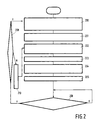
- Fig. 2 is a flowchart of a planning process to be used in parallel with the control process of Figure 3.
- Fig. 3 is a flowchart of a control process to be used in parallel with the planning process of Figure 2.
- Fig. 4 shows an example configuration of a high speed vehicle relative to a frame of reference.
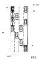
- Fig. 5 shows an example of a high speed vehicle in task space.
- Budding and differential budding are used to maneuver a robotic vehicle at higher speeds. "Higher speeds” is used herein to mean speeds sufficient so that small movements of the steering wheel produce nearly transverse motion relative to another moving object. For situations where the vehicle is moving at higher speeds, the orientation of the vehicle need not be used, making the pah planning process faster.
- a 'monitored property' is chosen.
- An example of a 'monitored property' is velocity.
- the 'monitored property' could be acceleration, but other dynamic properties, could be used instead.
- This monitored property is one which can be sensed each time the plan is updated. Integral properties and first derivatives can be generated from each monitored property. For example, if the monitored property is the velocity of a vehicle, then the relative distance, and acceleration over a period of time, can also be calculated from velocity measurements.
- One or more monitored properties may be needed to control a vehicle. For example, in addition to the velocity of the controlled vehicle and the frame of reference, the absolute lateral distance of the controlled vehicle and the frame of reference could be monitored.
- the configuration space is set up in terms of relative distance.
- a frame of reference herein abbreviated as F.O.R.
- the frame of reference commonly is considered to be at the origin in terms of relative measurements, although other origins could be used as well.
- This is usually a moving vehicle at the limit of the controlled vehicle's sensory capability. It may also be a focal point on the road, a fixed distance from the controlled vehicle.
- a new frame of reference may be determined at any time after a first plan is computed. For example, as the controlled vehicle overtakes the furthest sensed car, a new second furthest sensed car may be determined to be the new frame of reference.
- a frame of reference may be lost from view if it leaves headlight view at night, or if it turns off the highway.
- the 'monitored properties' of both the frame of reference and controlled vehicle are sensed.
- sensing we mean any form of data acquisition to determine the state of the frame of reference and controlled vehicle.
- the controlled car may be travelling at a velocity of 30 m.p.h. 500 feet behind a frame of reference which is travelling at a velocity of 25 m.p.h. in the same direction.
- the relative position of the controlled vehicle is then the derived distance between the frame of reference and the controlled car. In the example above it is 500 feet.
- the discretized configuration space calculated in Box 100, should be large enough to envelope both the frame of reference and the controlled vehicle. Although it is sufficient to have the configuration space range from the controlled vehicle distance to the frame of reference, it is preferred that larger areas be considered as an allowance for the time lag in the feedback system used to control the car.
- the two state indicator budflag with states BUD and DIFFBUD, is set to BUD.
- a background metric is established. This is done by establishing the reachable neighbourhood of nearby states, and assigning a cost to those motions.
- the capabilities of the controlled vehicle define the transitions. For example, a racing car's engine will determine the acceleration that it may achieve in one unit of time. In a configuration space defined by a moving frame of reference, acceleration greater than the frame of reference results in a forward motion relative to the frame of reference.
- the capabilities of the vehicle can also take into account the 'rules of the road'. For example, a car may be capable of accelerating to 100 mph, but the 'rules of the road' restrict the vehicle velocity to 55 mph. Another example capability is based on occupant comfort and could limit acceleration or deceleration to 5 m.p.h.
- the transitions represent motions which are the first derivative of the monitored property. Using the previous example, if the monitored property is velocity, then by monitoring the velocities of the frame of reference and controlled vehicle over a short period of time, the desired acceleration can be computed.
- the planning cycle time is the time it takes to compute the desired path.
- Obstacles in configuration space represent illegal states of the vehicle.
- Illegal states can be caused by geometrical obstructions.
- An example of a geometrical obstruction is a state corresponding to the positions where a vehicle physically hits or intersects the body of another vehicle.
- a third type of illegal states can be caused by adaptive constraints.
- An adaptive constraint may be a constraint determined based on the physics, current state and 'monitored property'.
- One example might be 'stopping distance' used for safety reasons.
- configuration states representing the controlled vehicle at a distance less than the 'stopping distance' from obstacles are illegal states.
- the 'stopping distance' is commonly defined as the braking distance plus the reaction distance.
- Reaction distance is how far a vehicle travels during the time it takes the controller to respond to a hazard and activate the brakes. The sensing time plus the cycle time is used to compute the reaction time and reaction distance.
- Braking distance is how far a vehicle travels from the moment the brakes are activated until it comes to a stop. Other forms of halting or slowing the vehicle could be used rather than standard brakes.
- An example of alternatives to brakes is slowing a direct drive motor in an electric car.
- the goal or goal states are transformed to the configuration space. They can be chosen in many ways. One way is to describe a 'general goal' and decompose it into smaller subgoals.
- the Robot Schema facility (Lyons, D.M. and Arbib, M.A. "A Formal Model of Computation for Sensory-Based Robotics", EEE Transactions on Robotics & Automation, Vol. 5, No. 3 June 1989 pp. 280-293) teaches sophisticated ways to decompose goals into subgoals.
- An example of a goal is to 'pass the car in front'. This may map into several goal states.
- the task space goal in this example would be 'in front of the car in front of the controlled vehicle', and 'to the front and left of the car in front of the controlled vehicle'.
- the configuration states corresponding to these positions are examples of goal states.
- budding or differential budding is performed. If budflag is set to BUD, then budding is performed. If budflag is set to DIFFBUD, then differential budding is performed. Although budding could always be used to find a new solution from scratch, the preferred approach is to use differential budding when obstacles, goals, or transitions change, because it yields a faster solution, and provides control directives while recomputation is occurring if the affected region does not include the current controlled state.
- a direction arrow may correspond to moving 'forward' toward the frame of reference.
- a desired motion may correspond to accelerating by 5 mph.
- setpoints are sent to the vehicle.
- One or more setpoints may be sent to the vehicle.
- One possible control might be the voltage controlling the fuel sent to the fuel injection system.
- the change in voltage used to increase velocity may not be the same as the change in voltage used to decrease velocity. For example, if the vehicle is to accelerate 5mph, the voltage may increase 0.2 volts. Alternatively, if the vehicle is to decelerate, the voltage may decrease 0.5 volts, while an electronic braking mechanism is activated.
- Box 110 sets the budflag to DIFFBUD. After box 110, the process in box 102 is performed.
- a first process and configuration space would be used to plan.
- a second process and configuration space would be used to read the setpoints which are sent as control directives to the vehicle.
- a duplicate is made, herein referenced to as a 'control copy of configuration space'.
- This control copy of configuration space is unchanged until the next full copy of configuration space is delivered by the planner. This method allows the control of the vehicle to continue without the delay that otherwise might occur while the planner is planning.
- Figure 2 contains a stepwise flowchart description of the planning process.
- the process in Figure 2 runs in parallel with the control process of Figure 3, and has the ability to alter the 'control copy of configuration space' needed by the control process of Figure 3, the vehicle can be controlled.
- Box 250 follows box 204.
- Box 208 tests if the frame of reference, obstacles, goals, or transitions have changed. If they have not, then the NO arrow is followed back to box 208. If the frame of reference, obstacles, goals, metric or transitions change, then replanning is required, and the YES arrow is followed to decision box 209. If either the frame of reference, or a cost transition has changed, then the YES arrow is followed back to box 200. Otherwise, one or more goals, obstacles, or transitions have changed, and the NO arrow can be followed to box 210.
- Box 210 sets the budflag to DIFFBUD. After box 210, the process in box 202 is performed.
- Figure 3 contains a stepwise flowchart description of the control process.
- direction arrows are followed.
- direction arrows could be followed state to state to the goal.
- the direction arrows are decomposed into control parameters.
- control parameters which are described in terms of the original capabilities, are sent to the vehicle.
- the method continues to box 306.
- the Figure 5 illustrates an example highway scenario.
- the highway has four lanes denoted as 504.
- the number of lanes can vary in a different example.
- the number of obstacle vehicles on the highway can also vary in a different example.
- the controlled vehicle is shown at its starting state denoted as 501.
- the desired goal state in which we intend the vehicle to reach is denoted as 502.
- the Frame of Reference (F.O.R.) is denoted as 503 in Figure 5.
- the vehicle at the lead of traffic is denoted as the frame of reference and is the furthest vehicle that can be readily sensed by the controlled car, 501.
- the sensory data is collected to report the positions of all of the vehicles in traffic relative to the sensed position of the frame of reference vehicle.
- all obstacles vehicles are travelling at a fixed speed of 35 m.p.h. and continue to do so while the later planning calculation takes place.
- the controlled vehicle, 501 is travelling at an initial speed of 25 m.p.h. in the far right lane shown in Figure 5.
- Controlled vehicle 501 is at a fixed forward distance of 500 feet behind the first obstacle also in the same lane.
- the goal is for controlled vehicle 501 to reach position 502, ahead of all the obstacle vehicles.
- the goal has to be achieved within the 'rules of the road' and without interfering with the obstacle vehicles.
- Box 203 in Figure 2 involves transforming the obstacles. Because the highway is a dynamic environment, the transformed obstacles include the body intersection as well as a margin of safety called the 'stopping distance'. In our example, the margin of safety is assumed to be the same size as the obstacle.
- Figure 6 shows the transformed obstacles and the transitions the controlled vehicle makes to reach the goal. In Figure 6, the obstacles are the solid boxes depicted as 601, and the margin of safety for each obstacle are the gray boxes depicted as 602.
- Box 204 involves determining the goal state in configuration space. The start and goal states are shown as 604 and 605 respectively in Figure 6. All obstacles are transformed to occupy certain regions of configuration space. These regions are forbidden to the controlled device.
- box 205 propagates waves.
- Differential budding is used if budflag is equal to BUD.
- the planning copy of configuration space is copied to the control copy in box 250. If there are any changes to the goal, metric or transformation then the step in box 203 onwards are repeated, otherwise if there are changes in the frame of reference or metric then all steps from box 201 onwards are repeated.
- the actual changing of the controlled vehicle's controlled parameter, i.e., velocity, is shown by the control method illustrated in Figure 3.
- the vehicle's properties are transformed into configuration space as indicated by box 306 in Figure 3.
- the controlled vehicle is at the starting state.
- the next step, shown in box 307, requires following the gradient using the control parameters provided by the neighbourhood and the setpoint provided by the state.
- the planner can follow the neighbourhood arrows along the path of minimum cost to the goal state.
- the control parameters are sent to the control mechanism of the vehicle between setpoints. This following has to be continued until the goal state is reached.
- the change in state is shown by the arrows depicted.
- the controlled device has to monitor that property and alter the state of obstacle in the configuration space. This involves repeating steps in boxes 203 to 250 in Figure 2.
- the arrows, denoted as 506, denote the transitions required by the controlled device 501 before it can reach the goal state 502. Each transition from start to goal state is achieved by a combination of adjusting the (x,y) positions.
- Another marine application is the piloting of large marine vessels into difficult seaports, for example, seaports in which the depth may not be sufficient for all vessels, and the waterbed topology is continuously changing because of sand bars, tides etc.
- Ship pilots have to continuously monitor the waterbed and port traffic while guiding the vessel to its allocated dock.
- the frame of reference may be specific vessel which could be moving and requires the controlled vessel to track it and stay a fixed distance relative to it.
- the frame of reference could be a geographical feature of the seabed, such as a drifting sand bar, which the vessel must avoid, based on short term sensory information.
- the highway-like analogy can also be applied to other domains such as air-traffic control.
- the objective is for the aircraft to avoid other aircraft and maintain the holding pattern allocated to them. They are allowed a very wide margin for safety reasons.
- the landing aircraft can make use of path planning technology to augment their guidance systems.
- In a holding pattern an aircraft would use aircraft in neighbouring patterns as the frames of reference to maintain correct position and alter the position or frame of reference as the situation changes.
- Using a ground based beacon may not be appropriate in all situations if other aircraft in the area are not doing exactly the same thing.
- the same technology may be used by air traffic controllers below to define paths for take-off and landing aircraft with the same parameters factored into the cost-metric.
Landscapes
- Engineering & Computer Science (AREA)
- Physics & Mathematics (AREA)
- General Physics & Mathematics (AREA)
- Geometry (AREA)
- Theoretical Computer Science (AREA)
- Automation & Control Theory (AREA)
- Aviation & Aerospace Engineering (AREA)
- Evolutionary Computation (AREA)
- Mechanical Engineering (AREA)
- Computer Hardware Design (AREA)
- Mathematical Analysis (AREA)
- General Engineering & Computer Science (AREA)
- Computational Mathematics (AREA)
- Pure & Applied Mathematics (AREA)
- Remote Sensing (AREA)
- Radar, Positioning & Navigation (AREA)
- Mathematical Optimization (AREA)
- Business, Economics & Management (AREA)
- Human Computer Interaction (AREA)
- Manufacturing & Machinery (AREA)
- Robotics (AREA)
- Human Resources & Organizations (AREA)
- Computer Networks & Wireless Communication (AREA)
- Multimedia (AREA)
- Electromagnetism (AREA)
- Computer Vision & Pattern Recognition (AREA)
- Ocean & Marine Engineering (AREA)
- Economics (AREA)
- Combustion & Propulsion (AREA)
- Strategic Management (AREA)
- Chemical & Material Sciences (AREA)
- Tourism & Hospitality (AREA)
- Development Economics (AREA)
- Quality & Reliability (AREA)
- Marketing (AREA)
- General Business, Economics & Management (AREA)
- Entrepreneurship & Innovation (AREA)
- Game Theory and Decision Science (AREA)
- Operations Research (AREA)
- Traffic Control Systems (AREA)
Claims (18)
- Procédé permettant de commander le déplacement d'un véhicule dans un espace de tâches physique comprenant un point de départ, un point de destination et des points d'emplacement d'un certain nombre d'obstacles, le procédé comprenant les étapes suivantes :- générer un espacé de configuration qui représente l'espace de tâches physique,- trouver, dans l'espace de configuration, une première route de coût minimum depuis le point de départ jusqu'au point de destination, et- commander un ou plusieurs paramètres affectant le déplacement du véhicule de façon que le véhicule suive cette route,caractérisé en ce que le procédé comprend en outre la transformation du point de départ, du point de destination et des points d'emplacement des nombreux obstacles en un système de référence qui se déplace par rapport à l'espace de tâches physique d'une manière pratiquement uniforme et en ce que l'espace de configuration généré se base sur le système de référence.
- Procédé suivant la revendication 1, dans lequel l'étape consistant à générer l'espace de configuration comprend le contrôle d'un ou de plusieurs éléments du déplacement du véhicule.
- Procédé suivant la revendication 2, dans lequel les paramètres commandés comprennent des dérivées dans le temps des éléments contrôlés.
- Procédé suivant la revendication 3, dans lequel les éléments contrôlés comprennent des composantes de vitesse du véhicule et dans lequel les paramètres commandés comprennent des composantes d'accélération du véhicule.
- Procédé suivant l'une quelconque des revendications 1 à 4, comprenant en outre les étapes répétitives suivantes :- mettre à jour l'espace de configuration pour refléter des changements dans l'espace de tâches physique et/ou des éléments du déplacement du véhicule,- trouver, dans l'espace de configuration mis à jour, une route suivante de coût minimum à partir du point de départ jusqu'au point de destination.
- Procédé suivant la revendication 5, dans lequel l'étape pour trouver la première route de coût minimum comprend le greffage d'ondes dans l'espace de configuration et dans lequel l'étape pour trouver la route suivante de coût minimum comprend le greffage différentiel d'ondes dans l'espace de configuration.
- Procédé suivant la revendication 6, dans lequel l'étape pour trouver la route suivante de coût minimum comprend :- la déterminaison si une métrique a changé dans l'espace de configuration,- le greffage des ondes dans l'espace de configuration si la métrique a changé, et- le greffage différentiel des ondes dans l'espace de configuration si la métrique n'a pas changé.
- Procédé suivant l'une quelconque des revendications 1 à 7, dans lequel sont exécutées, pendant la commande des paramètres, les étapes suivantes :- générer un second espace de configuration qui représente l'espace de tâches physique, et- trouver dans le second espace de configuration une seconde route de coût minimum à partir du point de départ jusqu'au point de destination,et ledit procédé comprenant en outre les étapes suivantes :- commander les paramètres affectant le déplacement du véhicule de telle sorte que le véhicule suive cette seconde route, et- trouver en variante des routes de coût minimum dans le premier et le second espaces de configuration tout en commandant les paramètres sur la base de la route déterminée la plus récente.
- Procédé suivant la revendication 8, dans lequel l'étape pour générer le second espace de configuration comprend la reproduction de l'espace de configuration original dans le second espace de configuration.
- Procédé suivant l'une quelconque des revendications 1 à 9, dans lequel la route de coût minimum est une route qui réduit au minimum la consommation de carburant.
- Procédé suivant l'une quelconque des revendications 1 à 10, dans lequel la route de coût minimum est une route qui réduit au minimum la distance parcourue.
- Procédé suivant l'une quelconque des revendications 1 à 11, dans lequel le système de référence se déplace à la même vitesse que le véhicule commandé.
- Procédé suivant l'une quelconque des revendications 1 à 11, dans lequel la route de coût minimum est déterminée pour éviter des collisions avec des obstacles qui se déplacent par rapport à l'espace de tâches physique et dans lequel le système de référence se déplace à la même vitesse que l'un des obstacles.
- Procédé suivant l'une quelconque des revendications 1 à 13, dans lequel le véhicule est une voiture ou un autre véhicule analogue à vitesse supérieure et dans lequel l'espace de tâches physique comprend une autoroute.
- Procédé suivant l'une quelconque des revendications 1 à 14, dans lequel le véhicule est un sous-marin suivant un autre bateau tout en évitant le fond de l'océan et d'autres obstacles.
- Procédé suivant l'une quelconque des revendications 1 à 15, dans lequel le choix du système de référence change en raison de changements des informations sensorielles.
- Procédé suivant la revendication 12, dans lequel le véhicule commandé est l'un parmi plusieurs véhicules se déplaçant en formation.
- Système permettant de commander le déplacement d'un véhicule dans un espace de tâches physique comprenant un point de départ, un point de destination et des points d'emplacement d'un certain nombre d'obstacles, le système comprenant :- un moyen pour générer un espace de configuration qui représente l'espace de tâches physique,- un moyen pour trouver, dans l'espace de configuration, une première route de coût minimum depuis le point de départ jusqu'au point de destination, et- un moyen pour commander un ou plusieurs paramètres affectant le déplacement du véhicule en réaction au moyen pour trouver la route de coût minimum de façon que le véhicule suive cette route,caractérisé en ce que ce système comprend un moyen pour transformer le point de départ, le point de destination et les points d'emplacement des nombreux obstacles en un système de référence qui se déplace par rapport à l'espace de tâches physique et en ce que le moyen pour générer l'espace de configuration est à même de baser l'espace de configuration sur le système de référence.
Applications Claiming Priority (2)
| Application Number | Priority Date | Filing Date | Title |
|---|---|---|---|
| US07/605,057 US5220497A (en) | 1987-11-20 | 1990-10-29 | Method and apparatus for controlling high speed vehicles |
| US605057 | 1990-10-29 |
Publications (3)
| Publication Number | Publication Date |
|---|---|
| EP0483905A2 EP0483905A2 (fr) | 1992-05-06 |
| EP0483905A3 EP0483905A3 (en) | 1992-07-08 |
| EP0483905B1 true EP0483905B1 (fr) | 1997-03-05 |
Family
ID=24422087
Family Applications (1)
| Application Number | Title | Priority Date | Filing Date |
|---|---|---|---|
| EP91202720A Expired - Lifetime EP0483905B1 (fr) | 1990-10-29 | 1991-10-21 | Méthode et appareil pour contrÔler des véhicules à grande vitesse |
Country Status (5)
| Country | Link |
|---|---|
| US (1) | US5220497A (fr) |
| EP (1) | EP0483905B1 (fr) |
| JP (1) | JPH04315300A (fr) |
| KR (1) | KR920007856A (fr) |
| DE (1) | DE69124918T2 (fr) |
Families Citing this family (29)
| Publication number | Priority date | Publication date | Assignee | Title |
|---|---|---|---|---|
| US5544282A (en) * | 1991-04-05 | 1996-08-06 | Chen; Pang C. | Method and apparatus for planning motions of robot manipulators |
| US5548773A (en) * | 1993-03-30 | 1996-08-20 | The United States Of America As Represented By The Administrator Of The National Aeronautics And Space Administration | Digital parallel processor array for optimum path planning |
| DE19546506A1 (de) * | 1995-12-13 | 1997-06-19 | Daimler Benz Ag | Fahrzeug-Navigationssystem und Signalverarbeitungsverfahren für ein solches Navigationssystem |
| US5913945A (en) * | 1996-05-02 | 1999-06-22 | Daimlerchrysler Corporation | Pedal linkage for robotic control of vehicle |
| US5865266A (en) * | 1996-05-02 | 1999-02-02 | Chrysler Corporation | Steering wheel linkage for robotic system for automated durability road (ADR) facility |
| US5991674A (en) * | 1996-05-02 | 1999-11-23 | Chrysler Corporation | Floor shifter linkage for robotic control of vehicle |
| US5821718A (en) * | 1996-05-07 | 1998-10-13 | Chrysler Corporation | Robotic system for automated durability road (ADR) facility |
| US6004016A (en) * | 1996-08-06 | 1999-12-21 | Trw Inc. | Motion planning and control for systems with multiple mobile objects |
| US5867089A (en) * | 1996-09-03 | 1999-02-02 | Chrysler Corporation | Base-to-remotely controlled vehicle communications for automated durability road (ADR) facility |
| US5938705A (en) * | 1996-09-03 | 1999-08-17 | Chrysler Corporation | Vehicle controller (VCON) for automated durability road (ADR) facility |
| US6141620A (en) * | 1996-09-03 | 2000-10-31 | Chrysler Corporation | Vehicle control system for automated durability road (ADR) facility |
| US5908454A (en) * | 1996-09-03 | 1999-06-01 | Chrysler Corporation | Operator interface for automated durability road (ADR) facility |
| US6061613A (en) * | 1996-09-03 | 2000-05-09 | Chrysler Corporation | Base station for automated durability road (ADR) facility |
| US5906647A (en) * | 1996-09-03 | 1999-05-25 | Chrysler Corporation | Vehicle mounted guidance antenna for automated durability road (ADR) facility |
| US6161071A (en) | 1999-03-12 | 2000-12-12 | Navigation Technologies Corporation | Method and system for an in-vehicle computing architecture |
| KR100520450B1 (ko) * | 1999-06-08 | 2005-10-12 | 주식회사 코캣 | 반도체 식각공정용 할로겐족 폐가스 처리제 및 이를 이용한 할로겐족 폐가스의 처리방법 |
| US6415226B1 (en) * | 1999-12-20 | 2002-07-02 | Navigation Technologies Corp. | Method and system for providing safe routes using a navigation system |
| US6405128B1 (en) | 1999-12-20 | 2002-06-11 | Navigation Technologies Corp. | Method and system for providing an electronic horizon in an advanced driver assistance system architecture |
| AU2006306523B2 (en) | 2005-10-21 | 2011-05-19 | Deere & Company | Systems and methods for switching between autonomous and manual operation of a vehicle |
| EP1961639A1 (fr) * | 2007-02-22 | 2008-08-27 | Nederlandse Organisatie voor toegepast- natuurwetenschappelijk onderzoek TNO | Système d'assistance à la conduite pour véhicule |
| EP2364891B1 (fr) * | 2010-03-12 | 2013-06-19 | Volvo Car Corporation | Methode pour permettre l'intervention d'un system automatique de support au conducteur |
| US20130103305A1 (en) * | 2011-10-19 | 2013-04-25 | Robert Bosch Gmbh | System for the navigation of oversized vehicles |
| US9056395B1 (en) | 2012-09-05 | 2015-06-16 | Google Inc. | Construction zone sign detection using light detection and ranging |
| US9221461B2 (en) * | 2012-09-05 | 2015-12-29 | Google Inc. | Construction zone detection using a plurality of information sources |
| US9195914B2 (en) | 2012-09-05 | 2015-11-24 | Google Inc. | Construction zone sign detection |
| US8996228B1 (en) | 2012-09-05 | 2015-03-31 | Google Inc. | Construction zone object detection using light detection and ranging |
| US10179583B2 (en) | 2016-03-29 | 2019-01-15 | Ford Global Technologies, Llc | Vehicle subsystem coordination and control |
| CN107452201B (zh) * | 2017-07-24 | 2020-05-08 | 重庆大学 | 一种考虑前车换道驶离时后车的跟驰加速度确定方法及跟驰行为建模方法 |
| CN110837255B (zh) * | 2019-11-08 | 2022-07-15 | 哈尔滨工程大学 | 一种适用于高速水面无人艇的自主危险规避方法 |
Family Cites Families (6)
| Publication number | Priority date | Publication date | Assignee | Title |
|---|---|---|---|---|
| JPS5773402A (en) * | 1980-10-23 | 1982-05-08 | Fanuc Ltd | Numerical control system |
| JPS57113111A (en) * | 1980-12-30 | 1982-07-14 | Fanuc Ltd | Robot control system |
| US4674048A (en) * | 1983-10-26 | 1987-06-16 | Automax Kabushiki-Kaisha | Multiple robot control system using grid coordinate system for tracking and completing travel over a mapped region containing obstructions |
| US4764873A (en) * | 1987-02-13 | 1988-08-16 | Dalmo Victor, Inc., Div. Of The Singer Company | Path blockage determination system and method |
| US4949277A (en) * | 1988-03-09 | 1990-08-14 | North American Philips Corporation | Differential budding: method and apparatus for path planning with moving obstacles and goals |
| EP0375055B1 (fr) * | 1988-12-23 | 1995-03-22 | Koninklijke Philips Electronics N.V. | Méthode et dispositif pour contrôler les manoeuvres d'un véhicule et véhicule équipé d'un tel dispositif |
-
1990
- 1990-10-29 US US07/605,057 patent/US5220497A/en not_active Expired - Fee Related
-
1991
- 1991-10-21 DE DE69124918T patent/DE69124918T2/de not_active Expired - Fee Related
- 1991-10-21 EP EP91202720A patent/EP0483905B1/fr not_active Expired - Lifetime
- 1991-10-25 KR KR1019910018789A patent/KR920007856A/ko not_active Abandoned
- 1991-10-29 JP JP3283049A patent/JPH04315300A/ja active Pending
Also Published As
| Publication number | Publication date |
|---|---|
| EP0483905A3 (en) | 1992-07-08 |
| EP0483905A2 (fr) | 1992-05-06 |
| DE69124918T2 (de) | 1997-08-28 |
| KR920007856A (ko) | 1992-05-27 |
| US5220497A (en) | 1993-06-15 |
| JPH04315300A (ja) | 1992-11-06 |
| DE69124918D1 (de) | 1997-04-10 |
Similar Documents
| Publication | Publication Date | Title |
|---|---|---|
| US5220497A (en) | Method and apparatus for controlling high speed vehicles | |
| US12208822B2 (en) | Trajectory determination for four-wheel steering | |
| CN110341711B (zh) | 一种基于码头环境的行驶轨迹生成系统及方法 | |
| CN109669461B (zh) | 一种复杂工况下自动驾驶车辆决策系统及其轨迹规划方法 | |
| EP2338029B1 (fr) | Commande et systèmes pour véhicules à conduite autonome | |
| EP4049916B1 (fr) | Procédé de commande de véhicule, système de commande de véhicule, et véhicule | |
| JP6972793B2 (ja) | 運転支援車両の走行制御方法及び走行制御装置 | |
| JP2853077B2 (ja) | 自動走行車両 | |
| US11414127B2 (en) | Trajectory tracking with four-wheel steering | |
| US20080059015A1 (en) | Software architecture for high-speed traversal of prescribed routes | |
| EP2685338A1 (fr) | Appareil et procédé pour la commande latérale d'un véhicule hôte lors d'un voyage dans des véhicules en groupe | |
| US10474149B2 (en) | Autonomous behavior control using policy triggering and execution | |
| US12037014B2 (en) | Method for determining an avoidance path of a motor vehicle | |
| US20210041882A1 (en) | Path Follower with Limited Steering Rate Controller | |
| US11279372B2 (en) | System and method for controlling a vehicle having an autonomous mode and a semi-autonomous mode | |
| JP7106872B2 (ja) | 車両の自動運転制御装置及び自動運転制御方法 | |
| Leedy et al. | Virginia Tech's twin contenders: A comparative study of reactive and deliberative navigation | |
| CN111923904B (zh) | 一种无人驾驶电动汽车的自主避障方法 | |
| JP2023539467A (ja) | 自動車両の横方向運動を制御するための制御方法 | |
| CN116300970B (zh) | 车辆自主编队方法及装置 | |
| Hu et al. | Decision-making system based on finite state machine for low-speed autonomous vehicles in the park | |
| CN111390922A (zh) | 一种自动驾驶机器人 | |
| CN115158355A (zh) | 一种多障碍物环境下的目标轨迹规划和跟踪方法 | |
| EP4561884B1 (fr) | Système de commande et procédé de commande de conduite autonome d'un véhicule | |
| US12617436B2 (en) | Trajectory prediction from multi-sensor fusion |
Legal Events
| Date | Code | Title | Description |
|---|---|---|---|
| PUAI | Public reference made under article 153(3) epc to a published international application that has entered the european phase |
Free format text: ORIGINAL CODE: 0009012 |
|
| AK | Designated contracting states |
Kind code of ref document: A2 Designated state(s): DE FR GB IT |
|
| PUAL | Search report despatched |
Free format text: ORIGINAL CODE: 0009013 |
|
| AK | Designated contracting states |
Kind code of ref document: A3 Designated state(s): DE FR GB IT |
|
| 17P | Request for examination filed |
Effective date: 19921229 |
|
| 17Q | First examination report despatched |
Effective date: 19941025 |
|
| GRAG | Despatch of communication of intention to grant |
Free format text: ORIGINAL CODE: EPIDOS AGRA |
|
| GRAH | Despatch of communication of intention to grant a patent |
Free format text: ORIGINAL CODE: EPIDOS IGRA |
|
| GRAH | Despatch of communication of intention to grant a patent |
Free format text: ORIGINAL CODE: EPIDOS IGRA |
|
| GRAH | Despatch of communication of intention to grant a patent |
Free format text: ORIGINAL CODE: EPIDOS IGRA |
|
| GRAA | (expected) grant |
Free format text: ORIGINAL CODE: 0009210 |
|
| AK | Designated contracting states |
Kind code of ref document: B1 Designated state(s): DE FR GB IT |
|
| REF | Corresponds to: |
Ref document number: 69124918 Country of ref document: DE Date of ref document: 19970410 |
|
| ITF | It: translation for a ep patent filed | ||
| ET | Fr: translation filed | ||
| PGFP | Annual fee paid to national office [announced via postgrant information from national office to epo] |
Ref country code: GB Payment date: 19970930 Year of fee payment: 7 |
|
| PGFP | Annual fee paid to national office [announced via postgrant information from national office to epo] |
Ref country code: FR Payment date: 19971021 Year of fee payment: 7 |
|
| PLBE | No opposition filed within time limit |
Free format text: ORIGINAL CODE: 0009261 |
|
| STAA | Information on the status of an ep patent application or granted ep patent |
Free format text: STATUS: NO OPPOSITION FILED WITHIN TIME LIMIT |
|
| 26N | No opposition filed | ||
| PG25 | Lapsed in a contracting state [announced via postgrant information from national office to epo] |
Ref country code: DE Free format text: LAPSE BECAUSE OF NON-PAYMENT OF DUE FEES Effective date: 19980701 |
|
| REG | Reference to a national code |
Ref country code: FR Ref legal event code: CD |
|
| PG25 | Lapsed in a contracting state [announced via postgrant information from national office to epo] |
Ref country code: GB Free format text: LAPSE BECAUSE OF NON-PAYMENT OF DUE FEES Effective date: 19981021 |
|
| GBPC | Gb: european patent ceased through non-payment of renewal fee |
Effective date: 19981021 |
|
| PG25 | Lapsed in a contracting state [announced via postgrant information from national office to epo] |
Ref country code: FR Free format text: LAPSE BECAUSE OF NON-PAYMENT OF DUE FEES Effective date: 19990630 |
|
| REG | Reference to a national code |
Ref country code: FR Ref legal event code: ST |
|
| PG25 | Lapsed in a contracting state [announced via postgrant information from national office to epo] |
Ref country code: IT Free format text: LAPSE BECAUSE OF NON-PAYMENT OF DUE FEES;WARNING: LAPSES OF ITALIAN PATENTS WITH EFFECTIVE DATE BEFORE 2007 MAY HAVE OCCURRED AT ANY TIME BEFORE 2007. THE CORRECT EFFECTIVE DATE MAY BE DIFFERENT FROM THE ONE RECORDED. Effective date: 20051021 |