EP0483934A1 - Caniveau à isolation gazeuse unipolaire - Google Patents
Caniveau à isolation gazeuse unipolaire Download PDFInfo
- Publication number
- EP0483934A1 EP0483934A1 EP91250269A EP91250269A EP0483934A1 EP 0483934 A1 EP0483934 A1 EP 0483934A1 EP 91250269 A EP91250269 A EP 91250269A EP 91250269 A EP91250269 A EP 91250269A EP 0483934 A1 EP0483934 A1 EP 0483934A1
- Authority
- EP
- European Patent Office
- Prior art keywords
- sections
- inner conductor
- piece
- jacket tube
- section
- Prior art date
- Legal status (The legal status is an assumption and is not a legal conclusion. Google has not performed a legal analysis and makes no representation as to the accuracy of the status listed.)
- Granted
Links
- 239000004020 conductor Substances 0.000 claims abstract description 46
- 239000012212 insulator Substances 0.000 claims abstract description 40
- 230000008878 coupling Effects 0.000 claims abstract description 20
- 238000010168 coupling process Methods 0.000 claims abstract description 20
- 238000005859 coupling reaction Methods 0.000 claims abstract description 20
- 239000002184 metal Substances 0.000 claims description 9
- 230000002093 peripheral effect Effects 0.000 claims description 3
- 238000006073 displacement reaction Methods 0.000 description 4
- 229910018503 SF6 Inorganic materials 0.000 description 1
- 230000004323 axial length Effects 0.000 description 1
- 230000000694 effects Effects 0.000 description 1
- 230000005684 electric field Effects 0.000 description 1
- 238000010438 heat treatment Methods 0.000 description 1
- 238000009434 installation Methods 0.000 description 1
- 238000009413 insulation Methods 0.000 description 1
- 238000007789 sealing Methods 0.000 description 1
- SFZCNBIFKDRMGX-UHFFFAOYSA-N sulfur hexafluoride Chemical compound FS(F)(F)(F)(F)F SFZCNBIFKDRMGX-UHFFFAOYSA-N 0.000 description 1
- 229960000909 sulfur hexafluoride Drugs 0.000 description 1
Images

Classifications
-
- H—ELECTRICITY
- H02—GENERATION; CONVERSION OR DISTRIBUTION OF ELECTRIC POWER
- H02G—INSTALLATION OF ELECTRIC CABLES OR LINES, OR OF COMBINED OPTICAL AND ELECTRIC CABLES OR LINES
- H02G5/00—Installations of bus-bars
- H02G5/06—Totally-enclosed installations, e.g. in metal casings
- H02G5/066—Devices for maintaining distance between conductor and enclosure
- H02G5/068—Devices for maintaining distance between conductor and enclosure being part of the junction between two enclosures
-
- H—ELECTRICITY
- H02—GENERATION; CONVERSION OR DISTRIBUTION OF ELECTRIC POWER
- H02G—INSTALLATION OF ELECTRIC CABLES OR LINES, OR OF COMBINED OPTICAL AND ELECTRIC CABLES OR LINES
- H02G5/00—Installations of bus-bars
- H02G5/002—Joints between bus-bars for compensating thermal expansion
Definitions
- the invention relates to a single-pole gas-insulated conduit with a jacket tube and a tubular inner conductor held centrally by support insulators in the jacket tube, in which the jacket tube is divided into sections provided with flanges and the inner conductor is also divided into mechanically and electrically connected sections.
- a conduit of this type is known for example from DE-U-85 12 872. It should be mentioned that such an object can also be referred to as a gas-insulated and single-phase metal-encapsulated tubular gas cable or as a gas-insulated busbar. Fields of application of such arrangements are preferably relatively short connecting distances between parts of a gas-insulated medium or high-voltage switchgear set up at a mutual distance or between such a switchgear and an associated transformer.
- a reliable current transfer despite the occurrence of thermal expansion can be ensured by arranging a multi-surface sliding contact element for the electrically conductive connection of two abutting sections of the inner conductor in at least one groove assigned to each section of a coupling piece that can be inserted into the sections.
- Such sliding contact elements are known in a number of different designs and therefore do not require any further explanation in the present context.
- the locking piece mentioned can be guided radially outward and projecting into the interior of the inner conductor, the coupling piece having a recess for the part of the locking piece projecting inwards.
- the coupling piece is fixed with respect to the inner conductor and this with respect to the post insulator. Since it is sufficient if a section of the inner conductor is secured at one point against axial displacement, the advantage is achieved that a change in length as a result of heating by the operating current is possible without hindrance.
- the sections of the inner conductor can therefore preferably be dimensioned such that a space which is suitable for absorbing thermal expansions remains.
- sections of the jacket tube and the inner conductor which are at right angles to one another can also be connected to one another, namely by means of a jacket tube corner piece or a coupling corner piece, the coupling corner piece communicates with the sections of the inner conductor to be connected via multi-surface sliding contact elements and is held centrally via a support insulator. In this way, unhindered thermal expansion is also ensured in the area of the rectangular deflection.
- the coupling corner piece for the sections of the inner conductor can consist of two sections connected at right angles, an inner conductor replacement piece being inserted between the metal sleeve and the section for holding the one section in the support insulator. This only needs to have approximately the axial length of the metal sleeve or can be made somewhat longer and with rounded edges.
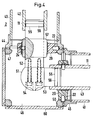
- FIG. 1 shows in a longitudinal section two abutting sections of a jacket tube and an inner conductor.
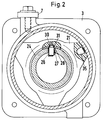
- FIG. 2 shows a cross section through a section of a jacket tube and an inner conductor and a partially cut post insulator.
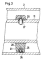
- FIG. 3 shows a longitudinal section through the parts according to FIG. 2.
- FIG. 1 An arrangement for the right-angled connection of two sections of a jacket tube and an inner conductor is shown in section in FIG.
- FIG. 1 shows part of a metal-encapsulated, gas-insulated conduit 1 which has a casing tube 2.
- the casing tube 2 is divided into several sections, of which two sections 3 and 4 are shown in FIG. 1, the ends of which are each provided with a flange 5 and 6, respectively.
- a Cable bridge 7 ensures a low-resistance electrical connection of sections 3 and 4.
- a round cord seal 10 inserted into a groove of flange 6 permits gas-tight connection of sections 3 and 4.
- the conduit 1 also has an inner conductor 11, which is also divided into sections.
- the inner conductor 11 is tubular, wherein there is an axial distance 14 between the sections 12 and 13, which allows an unimpeded relative displacement of the sections 12 and 13 when heated.
- a coupling piece 15, which has two multi-surface sliding contact elements 16 on its circumference, is used for the electrically conductive connection of the sections 12 and 13. This can be any suitable contact element, for example an element shown in DE-B-21 65 389, Figure 4, enlarged. By receiving each in a groove 17, the sliding contact elements 16 are secured against lateral displacement.
- a support insulator 20 is provided, which can be made in a known manner from an insulating plastic.
- the support insulator 20 has three arms 21, the circumferential surface of which is adapted to the inside diameter of the tubular casing 2 or of the sections 3 and 4.
- an electrode body 22 is molded or otherwise fastened, the end of which facing the center of the arrangement is rounded in order to equalize the electric field.
- the electrode body 22 projects beyond the circumferential surface of the associated arm 21 and projects with this protruding part into a groove 23 which is formed by corresponding recesses in the flanges 5 and 6 which abut one another.
- the support insulator 20 is axially fixed in this way with respect to the sections 3 and 4 of the casing tube 1 and is by electrically conductive connection of the electrode body 20 by clamping between the Flanges 5 and 6 are dielectric relieved.
- the support insulator 20 On its inner circumference, the support insulator 20 has a metal sleeve 24 whose inner diameter is adapted to the outer diameter of the sections 12 and 13 of the inner conductor 11.
- the section 13 of the inner conductor 11 is provided with a locking piece 25 near its end.
- the locking piece 25 is pin-shaped or bolt-shaped and is under the action of a helical spring 26, which is supported with a turn with an enlarged diameter in a conical depression 28 of an opening 27 on the circumference of section 13 and at the opposite end with a bent end leg inner end of the locking piece 25 abuts (Fig. 2). This is pressed radially outwards under the action of the spring.
- a pin 30 of the locking piece 25 projecting beyond the peripheral surface of the section 13 engages in an opening 31 in the metal sleeve 24.
- the coupling piece 15 has a recess 32 (FIG. 1) into which the end of the locking piece opposite the pin 30 is immersed. In this way, the coupling piece 15 is also prevented from axially shifting relative to the section 13.
- a resilient and radially projecting contact piece 36 is provided, which ensures the contact between the jacket tube and the electrode body 35 and thus the dielectric relief of the post insulator 20 when the post insulator 20 is inserted into the section of the jacket tube. If the inner conductor is provided at certain intervals with openings 27 which are conically countersunk on the outside, the support insulators 20 can be axially secured by means of the locking pieces 25 described.
- FIG. 4 shows a section 40 and a distance 41 of a jacket tube standing at right angles thereto, and a section 42 and a section 43 of an inner conductor standing at right angles thereto, which are mechanically and electrically connected to one another.
- the sections 40 and 41 of the casing tube are each provided with a flange 44 and 45 in the same way as was explained with reference to FIG. 1.
- a jacket pipe corner piece 46 is connected to these flanges and also has flanges 47 and 50.
- support insulators 20 are provided, the electrode bodies 22 of which are received in recesses or grooves between the flanges mentioned.
- a coupling corner piece 51 is used, which is composed of two sections 52 and 53 connected at right angles by means of screws 54. Each of the sections 52 and 53 is with a groove 55 for Providing a multi-surface sliding contact element 56 of the type already mentioned.
- the section 42 of the inner conductor ends in the arrangement according to FIG. 4 above the support insulator 20 inserted between the flanges 44 and 47.
- An inner conductor replacement piece 57 ensures that the section 52 of the coupling corner piece 51 nevertheless has the desired mechanical hold the post insulator 20 takes place.
- a locking piece 25 provides for the mutual axial securing between the section 52, the inner conductor replacement piece 57 and the support insulator 20 in the manner already described.
- the tubular casing corner piece 46 can be designed such that at least in the direction of the screws 54 free access from Outside after removing a sealing cover (60).
- a line duct can be assembled from the described components in a modular manner with little assembly work. Sections of the casing tube, sections of the inner conductor, bushings and coupling pieces form the most important parts. If two sections of the casing tube are joined together, a post insulator is also installed. An associated section of the inner conductor can be pushed through the metal sleeve of the post insulator until the latching piece 25 engages. This is also a coupling piece attached. The following section of the inner conductor is simply plugged onto the end of the coupling piece and is thereby mechanically centered and electrically connected via the sliding contact elements.
Landscapes
- Installation Of Bus-Bars (AREA)
- Insulating Bodies (AREA)
- Insulators (AREA)
Applications Claiming Priority (2)
| Application Number | Priority Date | Filing Date | Title |
|---|---|---|---|
| DE4034733 | 1990-10-30 | ||
| DE4034733A DE4034733A1 (de) | 1990-10-30 | 1990-10-30 | Einpoliger gasioslierter leitungskanal |
Publications (2)
| Publication Number | Publication Date |
|---|---|
| EP0483934A1 true EP0483934A1 (fr) | 1992-05-06 |
| EP0483934B1 EP0483934B1 (fr) | 1994-07-27 |
Family
ID=6417439
Family Applications (1)
| Application Number | Title | Priority Date | Filing Date |
|---|---|---|---|
| EP91250269A Expired - Lifetime EP0483934B1 (fr) | 1990-10-30 | 1991-10-02 | Caniveau à isolation gazeuse unipolaire |
Country Status (5)
| Country | Link |
|---|---|
| US (1) | US5185497A (fr) |
| EP (1) | EP0483934B1 (fr) |
| JP (1) | JPH04289717A (fr) |
| CA (1) | CA2054359A1 (fr) |
| DE (2) | DE4034733A1 (fr) |
Families Citing this family (8)
| Publication number | Priority date | Publication date | Assignee | Title |
|---|---|---|---|---|
| DE4321162A1 (de) * | 1993-06-25 | 1995-01-05 | Deutsche Aerospace Airbus | Flexible Rohrverbindung |
| DE19544476B4 (de) * | 1995-11-29 | 2007-03-15 | Abb Patent Gmbh | Vorrichtung zum Verbinden wenigstens einer rohrförmigen Stromschiene mit einer weiteren Stromschienenanordnung |
| EP0845844B1 (fr) * | 1996-11-29 | 2003-05-02 | Siemens Aktiengesellschaft | Bus de distribution d'énergie à isolement gazeuse avec un isolateur de support axialement fixe en forme de disque |
| DE10339822A1 (de) * | 2003-08-25 | 2005-04-14 | Siemens Ag | Gasisolierte Hochspannungsanlage |
| CN102369641B (zh) * | 2009-04-24 | 2015-09-30 | 三菱电机株式会社 | 高压电气设备的导体 |
| JP4781493B1 (ja) * | 2011-02-28 | 2011-09-28 | 三菱電機株式会社 | ガス絶縁母線 |
| FR2984617B1 (fr) * | 2011-12-14 | 2014-11-28 | Alstom Technology Ltd | Coude a angles d'orientation multiples pour lignes a haute tension |
| DE102017220050A1 (de) * | 2017-11-10 | 2019-05-16 | Siemens Aktiengesellschaft | Phasenleiter sowie Verfahren zum räumlichen Fixieren eines Armaturkörpers an einem Phasenleitergrundkörper |
Citations (2)
| Publication number | Priority date | Publication date | Assignee | Title |
|---|---|---|---|---|
| DE3240786A1 (de) * | 1982-11-04 | 1984-05-10 | Siemens AG, 1000 Berlin und 8000 München | Elektrische rohrschiene |
| DE8512872U1 (de) * | 1985-05-02 | 1985-08-14 | Ritter Starkstromtechnik GmbH & Co, 4600 Dortmund | SF↓6↓-isolierte einphasig metallgekapselte Rohrgaskabel für Mittelspannung |
Family Cites Families (22)
| Publication number | Priority date | Publication date | Assignee | Title |
|---|---|---|---|---|
| US2355111A (en) * | 1942-05-14 | 1944-08-08 | Gen Electric | Transmission line spacer |
| DE835465C (de) * | 1948-12-22 | 1952-03-31 | Siemens & Halske A G | Luftraumisolierte Hochfrequenzleitung |
| US3319214A (en) * | 1965-07-12 | 1967-05-09 | Dielectric Products Engineerin | Connectors |
| US3391243A (en) * | 1965-07-26 | 1968-07-02 | Westinghouse Electric Corp | Enclosed electric power transmission conductor |
| US3585270A (en) * | 1968-07-31 | 1971-06-15 | John George Trump | Gas-insulated transmission line |
| US3546356A (en) * | 1969-04-03 | 1970-12-08 | Ite Imperial Corp | Elbow construction for high voltage compressed-gas-insulated conductors |
| JPS4791Y1 (fr) * | 1969-10-16 | 1972-01-06 | ||
| DE2036270A1 (de) * | 1970-07-22 | 1972-01-27 | Siemens Ag | Elektrische Dreiphasenleitung mit Druckgasisoherung |
| BE785652A (fr) * | 1971-07-12 | 1973-01-02 | Alsthom Cgee | Dispositif de fixation d'un conducteur electrique creux dans une gaine coaxiale |
| CH536566A (de) * | 1971-09-16 | 1973-04-30 | Bbc Brown Boveri & Cie | Isoliergasgefüllt gekapselte elektrische Hochspannungsleitung |
| DE7141137U (de) * | 1971-10-30 | 1972-02-10 | Licentia | Metallgekapselter, druckgasisolier ter Stromleiter |
| DE2165389C3 (de) * | 1971-12-29 | 1981-03-26 | Multi-Contact AG, Basel | Hochstrompolumschalter |
| DE2313749C2 (de) * | 1973-03-20 | 1975-05-15 | Allgemeine-Elektricitaets-Gesellschaft Aeg-Telefunken, 6000 Frankfurt | Schutzrohr, insbesondere für gasisolierte Hochspannungsrohrleitungen |
| DE7318987U (de) * | 1973-05-19 | 1973-09-06 | Licentia Gmbh | Gekapselte, gasisolierte Hochspannungsleitung |
| DE2401093C2 (de) * | 1974-01-08 | 1982-06-24 | Siemens AG, 1000 Berlin und 8000 München | Isolierstoffkörper für eine metallgekapselte, gasisolierte Hochspannungsleitung |
| SE423942B (sv) * | 1979-10-31 | 1982-06-14 | Asea Ab | Gasisolerad hogspenningsanordning innehallande en stromledare uppburen av minst en stodisolator |
| US4316652A (en) * | 1979-11-05 | 1982-02-23 | General Signal Corporation | Phantom eliminator for signal lights |
| FR2472861A1 (fr) * | 1979-12-28 | 1981-07-03 | Alsthom Cgee | Dispositif de securite contre les arcs electriques |
| JPS5772721U (fr) * | 1980-10-20 | 1982-05-04 | ||
| CH662452A5 (de) * | 1983-08-31 | 1987-09-30 | Bbc Brown Boveri & Cie | Metallgekapselte, gasisolierte hochspannungsleitung. |
| US4556755A (en) * | 1985-04-11 | 1985-12-03 | Westinghouse Electric Corp. | Insulating spacer design for a modular gas-insulated transmission line |
| US4721829A (en) * | 1986-12-08 | 1988-01-26 | Westinghouse Electric Corp. | Gas insulated transmission line with shielded electrical joint assembly |
-
1990
- 1990-10-30 DE DE4034733A patent/DE4034733A1/de not_active Withdrawn
-
1991
- 1991-10-02 DE DE59102347T patent/DE59102347D1/de not_active Expired - Fee Related
- 1991-10-02 EP EP91250269A patent/EP0483934B1/fr not_active Expired - Lifetime
- 1991-10-25 JP JP3307082A patent/JPH04289717A/ja not_active Withdrawn
- 1991-10-28 CA CA002054359A patent/CA2054359A1/fr not_active Abandoned
- 1991-10-29 US US07/783,852 patent/US5185497A/en not_active Expired - Fee Related
Patent Citations (2)
| Publication number | Priority date | Publication date | Assignee | Title |
|---|---|---|---|---|
| DE3240786A1 (de) * | 1982-11-04 | 1984-05-10 | Siemens AG, 1000 Berlin und 8000 München | Elektrische rohrschiene |
| DE8512872U1 (de) * | 1985-05-02 | 1985-08-14 | Ritter Starkstromtechnik GmbH & Co, 4600 Dortmund | SF↓6↓-isolierte einphasig metallgekapselte Rohrgaskabel für Mittelspannung |
Also Published As
| Publication number | Publication date |
|---|---|
| DE4034733A1 (de) | 1992-05-07 |
| DE59102347D1 (de) | 1994-09-01 |
| JPH04289717A (ja) | 1992-10-14 |
| CA2054359A1 (fr) | 1992-05-01 |
| EP0483934B1 (fr) | 1994-07-27 |
| US5185497A (en) | 1993-02-09 |
Similar Documents
| Publication | Publication Date | Title |
|---|---|---|
| DD294376A5 (de) | Steckkupplung fuer hochspannungsplastkabel | |
| DE1490840B2 (de) | Elektrische steckkupplung zur verbindung koaxialer leitungen | |
| DE2132418C2 (de) | Kabelverbinder für Hochspannungskabel | |
| EP1129509B1 (fr) | Dispositif de raccordement | |
| DE2215757A1 (de) | Koaxialsteckverbindung | |
| EP0483934B1 (fr) | Caniveau à isolation gazeuse unipolaire | |
| DE2123549C3 (de) | Vorrichtung zum elektrischen Verbinden eines Stromschienensystems mit einem Anlagenbauteil | |
| DE4312617C2 (de) | Elektrisches Schaltfeld, insbesondere für Mittelspannungsanlagen | |
| EP0888657B1 (fr) | Installation de transmission d'energie a isolement gazeux a conducteurs internes fixes axialement a distance | |
| DE19605979C2 (de) | Strom-tragfähiges Verbindungselement für Rohrleitungen einer gasisolierten Schaltanlage | |
| DE29710984U1 (de) | Elektrische Steckverbindungseinrichtung | |
| EP0164023A2 (fr) | Assemblage pour connecter deux conducteurs | |
| DE4403571C1 (de) | Verbindungsmuffe für kunststoffisolierte Hochspannungsenergieversorgungskabel | |
| DE3507875C2 (de) | Koaxiale elektrische Steckvorrichtung | |
| DE3317202C2 (de) | Kapazitives Trennstück | |
| DE19613026C1 (de) | Winkelstück zur Verbindung zweier Abschnitte einer gasisolierten Rohrleiteranlage | |
| WO1996013087A1 (fr) | Installation electrique de distribution haute tension a sectionneur de puissance, a blindage metallique | |
| DE2707592C3 (de) | Steckverbindung | |
| DE4307728A1 (de) | Steckverbinder | |
| WO2006111338A2 (fr) | Interrupteur-sectionneur et equipement electrique dote de cet interrupteur sectionneur | |
| DE4135390C1 (en) | Current connecting plug for power supply - has rotatable fixing ring on housing allowing connection to housing of cooperating socket | |
| EP0675566B1 (fr) | Connecteur coaxial avec support de conducteur interne | |
| DE2855387C2 (de) | Längsgeteilte Kabelgarnitur aus Halbschalen | |
| DE29614717U1 (de) | Gasisolierte Energieübertragungsanlage mit in Abständen axial fixiertem Innenleiter | |
| DE2643606A1 (de) | Mehrpoliger elektrischer stecker |
Legal Events
| Date | Code | Title | Description |
|---|---|---|---|
| PUAI | Public reference made under article 153(3) epc to a published international application that has entered the european phase |
Free format text: ORIGINAL CODE: 0009012 |
|
| AK | Designated contracting states |
Kind code of ref document: A1 Designated state(s): CH DE FR GB IT LI SE |
|
| 17P | Request for examination filed |
Effective date: 19920521 |
|
| 17Q | First examination report despatched |
Effective date: 19931208 |
|
| GRAA | (expected) grant |
Free format text: ORIGINAL CODE: 0009210 |
|
| AK | Designated contracting states |
Kind code of ref document: B1 Designated state(s): CH DE FR GB IT LI SE |
|
| REF | Corresponds to: |
Ref document number: 59102347 Country of ref document: DE Date of ref document: 19940901 |
|
| GBT | Gb: translation of ep patent filed (gb section 77(6)(a)/1977) |
Effective date: 19940915 |
|
| ITF | It: translation for a ep patent filed | ||
| ET | Fr: translation filed | ||
| EAL | Se: european patent in force in sweden |
Ref document number: 91250269.7 |
|
| PLBE | No opposition filed within time limit |
Free format text: ORIGINAL CODE: 0009261 |
|
| STAA | Information on the status of an ep patent application or granted ep patent |
Free format text: STATUS: NO OPPOSITION FILED WITHIN TIME LIMIT |
|
| 26N | No opposition filed | ||
| PGFP | Annual fee paid to national office [announced via postgrant information from national office to epo] |
Ref country code: GB Payment date: 19970909 Year of fee payment: 7 |
|
| PGFP | Annual fee paid to national office [announced via postgrant information from national office to epo] |
Ref country code: SE Payment date: 19971029 Year of fee payment: 7 Ref country code: FR Payment date: 19971029 Year of fee payment: 7 |
|
| PGFP | Annual fee paid to national office [announced via postgrant information from national office to epo] |
Ref country code: DE Payment date: 19971218 Year of fee payment: 7 |
|
| PGFP | Annual fee paid to national office [announced via postgrant information from national office to epo] |
Ref country code: CH Payment date: 19980120 Year of fee payment: 7 |
|
| PG25 | Lapsed in a contracting state [announced via postgrant information from national office to epo] |
Ref country code: GB Free format text: LAPSE BECAUSE OF NON-PAYMENT OF DUE FEES Effective date: 19981002 |
|
| PG25 | Lapsed in a contracting state [announced via postgrant information from national office to epo] |
Ref country code: SE Free format text: LAPSE BECAUSE OF NON-PAYMENT OF DUE FEES Effective date: 19981003 |
|
| PG25 | Lapsed in a contracting state [announced via postgrant information from national office to epo] |
Ref country code: LI Free format text: LAPSE BECAUSE OF NON-PAYMENT OF DUE FEES Effective date: 19981031 Ref country code: CH Free format text: LAPSE BECAUSE OF NON-PAYMENT OF DUE FEES Effective date: 19981031 |
|
| GBPC | Gb: european patent ceased through non-payment of renewal fee |
Effective date: 19981002 |
|
| REG | Reference to a national code |
Ref country code: CH Ref legal event code: PL |
|
| EUG | Se: european patent has lapsed |
Ref document number: 91250269.7 |
|
| PG25 | Lapsed in a contracting state [announced via postgrant information from national office to epo] |
Ref country code: FR Free format text: LAPSE BECAUSE OF NON-PAYMENT OF DUE FEES Effective date: 19990630 |
|
| REG | Reference to a national code |
Ref country code: FR Ref legal event code: ST |
|
| PG25 | Lapsed in a contracting state [announced via postgrant information from national office to epo] |
Ref country code: DE Free format text: LAPSE BECAUSE OF NON-PAYMENT OF DUE FEES Effective date: 19990803 |
|
| PG25 | Lapsed in a contracting state [announced via postgrant information from national office to epo] |
Ref country code: IT Free format text: LAPSE BECAUSE OF NON-PAYMENT OF DUE FEES;WARNING: LAPSES OF ITALIAN PATENTS WITH EFFECTIVE DATE BEFORE 2007 MAY HAVE OCCURRED AT ANY TIME BEFORE 2007. THE CORRECT EFFECTIVE DATE MAY BE DIFFERENT FROM THE ONE RECORDED. Effective date: 20051002 |