EP0483962A1 - Dispositif de fermeture à pression et méthode - Google Patents
Dispositif de fermeture à pression et méthode Download PDFInfo
- Publication number
- EP0483962A1 EP0483962A1 EP91308193A EP91308193A EP0483962A1 EP 0483962 A1 EP0483962 A1 EP 0483962A1 EP 91308193 A EP91308193 A EP 91308193A EP 91308193 A EP91308193 A EP 91308193A EP 0483962 A1 EP0483962 A1 EP 0483962A1
- Authority
- EP
- European Patent Office
- Prior art keywords
- rollers
- spring
- roller
- pressure
- recited
- Prior art date
- Legal status (The legal status is an assumption and is not a legal conclusion. Google has not performed a legal analysis and makes no representation as to the accuracy of the status listed.)
- Granted
Links
Images


Classifications
-
- B—PERFORMING OPERATIONS; TRANSPORTING
- B43—WRITING OR DRAWING IMPLEMENTS; BUREAU ACCESSORIES
- B43M—BUREAU ACCESSORIES NOT OTHERWISE PROVIDED FOR
- B43M5/00—Devices for closing envelopes
- B43M5/04—Devices for closing envelopes automatic
- B43M5/047—Devices for closing envelopes automatic using pressure-sensitive adhesive
-
- Y—GENERAL TAGGING OF NEW TECHNOLOGICAL DEVELOPMENTS; GENERAL TAGGING OF CROSS-SECTIONAL TECHNOLOGIES SPANNING OVER SEVERAL SECTIONS OF THE IPC; TECHNICAL SUBJECTS COVERED BY FORMER USPC CROSS-REFERENCE ART COLLECTIONS [XRACs] AND DIGESTS
- Y10—TECHNICAL SUBJECTS COVERED BY FORMER USPC
- Y10T—TECHNICAL SUBJECTS COVERED BY FORMER US CLASSIFICATION
- Y10T156/00—Adhesive bonding and miscellaneous chemical manufacture
- Y10T156/17—Surface bonding means and/or assemblymeans with work feeding or handling means
- Y10T156/1702—For plural parts or plural areas of single part
- Y10T156/1712—Indefinite or running length work
- Y10T156/1741—Progressive continuous bonding press [e.g., roll couples]
Definitions
- an extremely simple, inexpensive, and straight forward pressure sealer which is designed to handle business forms on a manual feed or semi-manual feed basis.
- some of the documents may not make it all the way through the sealer. It is impractical to feed those documents through again; however, utilizing the machine according to the invention, those documents can be manually run through to be sealed in a very simple yet effective manner.
- the simple, easy to use machine according to the invention is highly desirable.
- a basic manual feed pressure sealer for sealing adhesive strips of pressure sensitive adhesive associated with business forms.
- the apparatus comprises the following elements: A frame. Conveying means for conveying a business elements: A frame. Conveying means for conveying a business form past the frame, the conveying means consisting essentially of a first narrow width roller rotatable about a first horizontal axis, a second narrow width roller rotatable about a second horizontal axis, a drive motor, and gearing means interconnecting the drive motor to the first and second rollers.
- pressure applying means for applying pressure to the business forms when being conveyed in a first direction along a line tangent to both the first and second rollers, the pressure applying means comprising third and fourth narrow width rollers rotatable about third and fourth axes parallel to and aligned with the first and second axes, respectively, and means for biasing the third and fourth rollers toward contact with the first and second rollers so that as a business form is conveyed by the first and second rollers pressure is applied thereto by the third and fourth rollers.
- the gearing means preferably comprises only three gears, made of Delrin or like plastic, a pinion gear driven by the motor, and meshing with two other gears, one integral with each of the first and second rollers.
- the third and fourth rollers preferably comprise sections of ball bearings.
- the frame includes a platform leading to the first roller, and has a flap to prevent pinching of the operator's fingers.
- Spring pressure is preferably applied to the third and fourth rollers with a mechanism that provides adjustment of the spring pressure, or can be completely disabled to release all spring pressure and moved away to allow easy inspection and/or replacement of the components.
- the invention provides spring biasing means for applying a spring force between a stationary flange and one or more biassed elements comprising a screw threaded opening of a first diameter in said stationery flange; a spring pressure adjusting collar having a screw threaded opening therein of the first diameter; a coil spring; and a spring positioning plate.
- the spring pressure adjusting collar is disposed on the underside of the flange with the screw threaded openings therein in alignment; the spring engaging the adjusting collar at one end thereof, and operatively engaging the plate at the other end thereof.
- a first bolt has external screws with the first diameter and has a length less than the length from the flange to the plate when the spring is in extended position, the spring biasing the plate into operative engagement with the one or more elements to apply a spring pressure thereto.
- the biasing means of the apparatus is preferably of this form.
- the spring positioning plate preferably has a screw threaded opening therein having a second diameter, smaller than the first diameter; and wherein the spring biasing means further comprises a second bolt, interchangeable with the first bolt, and having external threads thereon of the second diameter, and having a length greater than the length from the flange to the plate when the spring is in extended position.
- roller yokes are provided for the third and fourth rollers, each roller yoke operatively attaching a roller to the frame for rotation about its axis and for relative movement toward and away from the first and second rollers.
- Each roller yoke has means for engaging the spring positioning plate so that the bias of the coil spring is applied to the third and fourth rollers through the spring positioning plate and the roller yokes.
- Each of the roller yokes is releasably pivotally mounted to the frame about its own yoke axis so that when the second bolt is fully threaded into the spring positioning plate, the spring is compressed so that the roller yoke may be pivoted about its yoke axis and disconnected from the frame, but when the first bolt is in operative association with the flange the pressure of the spring prevents the yokes from being significantly pivotally movable about the yoke axes.
- the biasing means also preferably comprises a spring button having a through extending opening therein large enough to allow clear passage of the second bolt therethrough, a spring positioning central post, and a rounded head engaging the spring positioning plate.
- the coil spring engages the head on the opposite side thereof from the plate, and surrounds the post, and operatively engages the spring positioning plate through the head.
- the invention also contemplates a method of handling business forms.
- the method comprises the steps of: (a) manually feeding a business form into operative association with the rollers so that the rollers apply pressure to one of the plurality of pressure sensitive adhesive strips to seal the business form together at that strip; and (b) after step (a), repeating manually moving the business form into operative association with each of the other unsealed adhesive strips, in turn, until all desired adhesive strips of the business form have been sealed.
- the force being applied by the rollers is only applied to the approximate area of the predetermined width of adhesive of each strip.
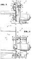
- FIGURES 1 through 4 An exemplary pressure applying apparatus for applying pressure to business forms to activate pressure sensitive adhesive associated with the forms to seal one part of the form to another, is illustrated generally by reference numeral 10 in FIGURES 1 through 4.
- the apparatus 10 is adapted to be mounted on a "table top", being small in size, simple in construction, and readily transportable from place to place. It is designed primarily for manual, or semi-manual, operation, effecting proper pressure sealing of adhesive strips utilizing the same basic force applicating procedure as is disclosed in co-pending application serial number 90302602.9 (and the disclosure of which has been incorporated by reference herein).
- the frame is formed of several different components, and for the exemplary embodiment illustrated in the drawings includes a base (11), a folded metal sheet (12), a lead in platform (13), a main support (14), and a safety and cosmetic outer enclosure (15).
- the frame components typically are made of metal.
- the apparatus (10) also comprises conveying means for conveying a business form past the frame (11-15).
- the conveying means preferably consists of only two narrow width (e.g. having a peripheral surface width of less than about an inch, typically about one-half inch) rollers, namely first roller (17) and second roller (18).
- the rollers are mounted by shaft pins (19, 20) respectively -- which are received by both of the frame components (12, 14) -- for rotation about parallel horizontal axes.
- the conveying means further comprises a drive motor (21) (FIGURES 3 and 4), typically an electric motor (cord and plug not shown) that is operated by a 120 volt AC current and has an integral gear reducing box associated therewith.
- the conveying means further comprises gearing means interconnecting the drive motor (21) to the rollers (17, 18) to effect rotation thereof about the axes defined by their shafts (19, 20).
- the gearing means consists of just three gears, a drive gear (22) connected to the output shaft (23) from the gear reducer associated with the motor (21), and a gear integral with each roller 17, 18, and mounted on the shafts 19, 20, respectively, such as the gear 25 shown in FIGURE 3 mounted to the shaft 20 behind second roller 18, the first roller 17 having a comparable gear 24 (shown in dotted line in FIGURE 2).
- the gears 22, 24, 25, be made of Delrin, or other non-ferrous metals or plastic composites having strength, lubricity, and manufacturability properties suitable for this application.
- the second roller 18 has a diameter enough larger than the diameter of the first roller 17 to effect pull up of a business form feeding from the first roller 17 to the second roller 18 (e.g. a diameter several hundredths of an inch larger).
- a business form is placed on the lead in platform 13 and is moved in the direction of arrow 27 toward the roller 17.
- a safety flap is provided in order to prevent the operator from moving his or her fingers into the dangerous high pressure area at roller 17.
- the safety flap such as a flap of leather or plastic material -- is illustrated schematically in FIGURES 1 and 2 by reference numeral 28, and may be mounted either on the cosmetic housing 15, or the portion 29 of the platform component 13, upstanding from the lead in surface 30 to the roller 17.
- the machine 10 also comprises pressure applying means for applying pressure to the business forms when being conveyed in the direction 27 along the platform surface 30 tangent to the upper surfaces of both rollers 17, 18.
- the pressure applying means comprises third and fourth rollers 32, 33, respectively, which are biased -- preferably by coil spring 34 -- into engagement with the top surfaces of the rollers 17, 18.
- the rollers 32, 33 also have a narrow width, approximately the same as that of the rollers 17, 18. Note that the third and fourth rollers 32, 33 are rotatable about axes defined by shaft stubs 35, 36, which axes are parallel to the axes defined by shafts 19, 20, and are preferably vertically in alignment therewith.
- Each roller 32, 33 may comprise a standard ball bearing, if desired.
- the spring bias provided by the coil spring 34 preferably is adjustable to vary the amount of pressure applied by the rollers 32, 33 to the form adhesive strip passing between the rollers 17, 32 and the rollers 18, 33.
- roller mounting yokes 40 seen most clearly in use in FIGURES 2 through 4 and 8, and in isolation in FIGURES 5 through 6 -- are provided.
- Each yoke 40 is preferably formed by a single piece of metal which is bent into a contoured channel configuration having side walls 41, a top wall 42, and an open bottom.
- the edges 43 defining the bottom include semi-circular recesses 44 therein for a loose receipt of the shaft associated with the third or the fourth roller (e.g. either shaft 35 or 36) to provide a bearing surface for the shaft, a semi-circular opening 44 engaging a portion of the shaft on either side of the roller 32, 33.
- the yoke 40 also includes an extension 45 having an upwardly facing semi-circular openings 46 therein which are adapted to engage a shaft 47 (see FIGURES 2, 3, and 8 in particular) which defines a pivot axis for the yoke 40, and thus allowing relative movement between the rollers 17, 32 and 18, 33 against the pressure of the spring 34.
- the axis of rotation defined by the shafts 47 are horizontally spaced from the axes defined by the shafts 35, 36.
- a collar 48 is preferably mounted on the free end of each shaft 47 to prevent movement of the yoke 40 off the shaft 47 in the direction of elongation thereof.
- the shafts 47 are themselves mounted for ready detachment from the frame component 14, as by removing the block 49 (see FIGURE 3) mounting each shaft 47.
- the block 49 may be adjustable up and down with respect to the frame 14 by Allen screws 50 movable in elongated slots 51 when loosened, and holding the block 49 against the frame 14 when the desired position is reached. Also, the block 49 may be completely detached from the apparatus 10 by unscrewing Allen screws 52.
- Spring pressure from coil spring 34 is actually applied to the yokes 40 -- and thus to the third and fourth rollers 32, 33 -- by the pin 55 associated with each yoke 40, and extending between the side walls 41 thereof opposite the pivot engaging semi-circle 46.
- the pressure of the spring 34 is transmitted to the pins 55 through a spring positioning plate 56, seen in FIGURES 8 through 10.
- FIGURES 8 through 10 The components of the spring biasing force application structure are illustrated most clearly in FIGURES 8 through 10. They include a flange 58 which is welded or otherwise stationarily mounted to the frame component 14 adjacent the top thereof, and has support portions 59. As seen in FIGURE 9, the flange 58 has a through-extending screw threaded opening 60 therein, which has a first diameter. That diameter is the same as the diameter of the external screw threads 61 on a first bolt 62 having a head 63.
- the spring pressure adjusting collar 64 has an internal screw threaded opening 65 which also has the first diameter, and is adapted to cooperate with the external threads 61 of the bolt 62. It has a main body shaft 65 and an upper head 66, the head 66 having a plurality of blind bores 67 formed therein for engagement by a tool to allow rotation of the adjustor collar 64.
- the coil spring 34 is centered by extending around the shaft portion 65 of the collar 64.
- the spring positioning plate 56 On the opposite end of the coil spring 34 from the adjusting collar 64 is the spring positioning plate 56.
- the spring positioning plate 56 also has an internal screw threaded opening 68 (see FIGURE 10) therein, the opening 68 having a second diameter less than the first diameter.
- the opening 68 there preferably is a tubular extension 69 from the bottom of the plate 56 which allows a sufficient length of thread to be provided to perform the necessary functions according to the invention.
- a spring button 70 is provided.
- the spring button 70 has a smooth faced internal opening 71 therein at least of the same diameter as the second diameter 68 (preferably slightly larger), and it has a central post 72 which is adapted to be received within the coils of the spring 34 to center the spring 34. It also has a head 73 having a rounded bottom 74, the rounded bottom 74 engaging the top surface of the plate 56 and pivotal with respect thereto to facilitate proper location of the spring 34 during use.
- the adjustment means also comprises a second bolt 76 (see FIGURE 10) having screw threaded portions 77 thereof of the second diameter to engage the internal screw threaded opening 68 of the plate 56.
- the bolt 76 is much longer than the bolt 62.
- the bolt 62 need have a length only sufficient to attach the collar 64 tightly to the under surface 78 of the stationary flange 58. That is it has a length less than the distance from flange 58 to the bottom of the coil spring 34 in a normal position thereof.
- the bolt 76 on the other hand, must have a length sufficient so that when the head 79 thereof is in engagement with the top face of the flange 58 threads 77 will engage the internal threads 68 and the plate 56.
- the motor 21 rotates the gear 22, which in turn rotates the gears 17 and 18 in the direction illustrated in FIGURE 2, to drive the first and second rollers 17, 18.
- the spring 34 acting between the adjusting collar 64 and the plate 56 --which engages the pins 55 -- biases the rollers 32, 33 into tangential contact with the tops of the rollers 17, 18.
- An operator grabs a business form, pushes an unsealed longitudinal edge thereof against the upright portion 29 of the frame component 13 while laying the form on the platform surface 30, and manually pushes the form in the direction of arrow 27 toward the first roller 17.
- the flap 28 prevents the operator from moving his fingers into engagement with the rollers.
- an appropriately sized tool in an opening 67 (typically four openings are provided around the periphery of the head 66 of the adjusting collar 64) which moves the adjusting collar 64 on the external shaft 61 of the first bolt 62 either downwardly toward the plate 56, or upwardly toward the underside 78 of the flange 58.
- the bolt 62 stays in the position it has been moved with respect to the flange 58 since the thread 61 thereof engages the internal thread of the opening 60 in the flange 58, the head 63 engaging the upper surface of the flange 58.
- the spring pressure must first be relieved. This is accomplished by unscrewing the first bolt 62 completely from the flange 58 and adaptor 64, and then sticking the second, thinner, longer bolt 76 into the opening 60, through the adaptor 64, spring 34, and internal passage 71 in button 70, into engagement with the interiorly threaded opening 68 of the spring positioning plate 56. The second bolt 76 is tightened down into opening 68, and as it is tightened it draws the spring plate 56 closer to it.
- the plate 56 draws closer to the head 79 of the second bolt 76, it finally gets to the point where it no longer presses down on the pins 55 of the yokes 40, and finally when the spring 34 is essentially completely compressed (see FIGURE 8), the pins 55 will no longer engage the plate 56, therefore the yokes 40 may be pivoted about their pivot axes defined by the shafts 47 -- as illustrated in FIGURE 8 -- so that they are moved away from the machine, including the rollers 32, 33 which may be readily detached from the yokes 40 (as illustrated on the right hand side in FIGURE 8).
Landscapes
- Package Closures (AREA)
- Delivering By Means Of Belts And Rollers (AREA)
- Folding Of Thin Sheet-Like Materials, Special Discharging Devices, And Others (AREA)
Applications Claiming Priority (2)
| Application Number | Priority Date | Filing Date | Title |
|---|---|---|---|
| US605797 | 1984-05-01 | ||
| US07/605,797 US5540806A (en) | 1990-10-31 | 1990-10-31 | Tabletop pressure sealer |
Publications (2)
| Publication Number | Publication Date |
|---|---|
| EP0483962A1 true EP0483962A1 (fr) | 1992-05-06 |
| EP0483962B1 EP0483962B1 (fr) | 1995-06-14 |
Family
ID=24425256
Family Applications (1)
| Application Number | Title | Priority Date | Filing Date |
|---|---|---|---|
| EP91308193A Expired - Lifetime EP0483962B1 (fr) | 1990-10-31 | 1991-09-06 | Dispositif de fermeture à pression et méthode |
Country Status (6)
| Country | Link |
|---|---|
| US (2) | US5540806A (fr) |
| EP (1) | EP0483962B1 (fr) |
| AU (1) | AU652782B2 (fr) |
| CA (1) | CA2053379A1 (fr) |
| DE (1) | DE69110405T2 (fr) |
| NZ (1) | NZ239795A (fr) |
Cited By (1)
| Publication number | Priority date | Publication date | Assignee | Title |
|---|---|---|---|---|
| EP1661695A1 (fr) * | 2004-11-24 | 2006-05-31 | GMP Co., Ltd. | Dispositif d'actionnement de rouleaux avec un plateau de chargement d'un dispositif à laminer |
Families Citing this family (18)
| Publication number | Priority date | Publication date | Assignee | Title |
|---|---|---|---|---|
| US5290385A (en) * | 1992-03-25 | 1994-03-01 | Moore Business Forms, Inc. | Multiple set pressure sealer rollers |
| US5772841A (en) * | 1995-12-26 | 1998-06-30 | Bescorp Inc. | In-line pressure sealer |
| US5728257A (en) * | 1996-05-08 | 1998-03-17 | Lee; Seung-Hun | Pouch laminator |
| US5810965A (en) * | 1997-04-07 | 1998-09-22 | Fwu; Jason | Thermal embossing/laminating system of printing machine |
| US6227272B1 (en) | 1998-12-15 | 2001-05-08 | Wayne R. Lindsay | Portable mechanical device for sealing material treated with pressure sensitive glue |
| GB9828608D0 (en) * | 1998-12-23 | 1999-02-17 | Printed Forms Equip | Pressure sealing apparatus & method |
| GB2378413B (en) * | 1998-12-23 | 2003-05-14 | Printed Forms Equip | Apparatus and methods for pressure sealing |
| US6153048A (en) * | 1999-02-05 | 2000-11-28 | The Hedman Company | Pressure sealer roller arrangement |
| US6539379B1 (en) * | 1999-08-23 | 2003-03-25 | Oblix, Inc. | Method and apparatus for implementing a corporate directory and service center |
| US6622767B2 (en) * | 2001-02-16 | 2003-09-23 | Stork Fabricators, Inc. | Multi-stage shrink-wrap sealing and cutting apparatus |
| US6626223B2 (en) | 2001-04-03 | 2003-09-30 | Moore North America, Inc. | Pressure sealer for nested documents |
| US6402015B1 (en) | 2001-05-08 | 2002-06-11 | Winkeler + Dunnebrier, Ag | Envelope having dual function adhesive |
| US6805179B2 (en) * | 2001-05-16 | 2004-10-19 | Xyron, Inc. | Article laminating apparatus with operation-adjusting cartridge detection and/or improved heating and/or improved cutting |
| US20070235142A1 (en) * | 2006-03-29 | 2007-10-11 | Tex Year Industries Inc. | Laminator |
| US8047252B2 (en) * | 2008-12-19 | 2011-11-01 | United Technologies Corporation | Modular component pressure application fixture |
| DE102011002889A1 (de) * | 2011-01-19 | 2012-07-19 | Maping Kommandiittiyhtiö L. Huotari | Auf grafischem Gebiet verwendbares Gerät und Verfahren zur Verwendung des auf grafischem Gebiet geeigneten Geräts |
| TWM448450U (zh) * | 2012-05-30 | 2013-03-11 | yao-zhang Lin | 可作淋膜編織袋貼合包底之全自動製袋機 |
| CN111591062B (zh) * | 2020-05-26 | 2021-08-06 | 浙江华龙机械股份有限公司 | 一种可根据纸张厚度旋转装订的印刷用装订设备 |
Citations (3)
| Publication number | Priority date | Publication date | Assignee | Title |
|---|---|---|---|---|
| US4343129A (en) * | 1976-04-27 | 1982-08-10 | G.B.R., Ltd. | Mechanism of making an envelope |
| US4450037A (en) * | 1983-06-22 | 1984-05-22 | Pitney Bowes Inc. | Envelope flap sealing device |
| US4926787A (en) * | 1989-05-19 | 1990-05-22 | Pitney Bowes Inc. | Envelope flap moistening apparatus |
Family Cites Families (16)
| Publication number | Priority date | Publication date | Assignee | Title |
|---|---|---|---|---|
| US426728A (en) * | 1890-04-29 | Envelope moistener and sealer | ||
| US2944587A (en) * | 1960-07-12 | Laminating machines | ||
| US891701A (en) * | 1906-06-05 | 1908-06-23 | Charles T Wright | Stamp-affixer. |
| US2381054A (en) * | 1943-07-31 | 1945-08-07 | Whiting Corp | Vehicle washing apparatus |
| US2893468A (en) * | 1955-08-31 | 1959-07-07 | William R Fieroh | Plastic heat-sealing apparatus |
| US3163352A (en) * | 1962-05-07 | 1964-12-29 | Studley Paper Company Inc | Paper bags |
| US3749631A (en) * | 1971-04-26 | 1973-07-31 | Dapak Systems Inc | Method and apparatus for preparing and assembling communications for mass distribution |
| US3770550A (en) * | 1971-09-03 | 1973-11-06 | M Levitan | Packet-type laminating machine |
| US4347219A (en) * | 1979-12-29 | 1982-08-31 | Honda Giken Kogyo Kabushiki Kaisha | Catalytic converter for exhaust-gas cleaning use and method of assembling same |
| US4426035A (en) * | 1980-03-13 | 1984-01-17 | Hammex Machines Ltd. | Packaging |
| US4451320A (en) * | 1982-01-11 | 1984-05-29 | Marvel Fred D | Packet-type laminator |
| SE8505242L (sv) * | 1985-11-06 | 1987-05-07 | Stralfors Ab Th | Forslutningsmaskin for arkat, limbelagt material |
| US5019203A (en) * | 1986-02-19 | 1991-05-28 | D&K Custom Machine Design, Inc. | Double sided laminating machine |
| US4721502A (en) * | 1986-09-08 | 1988-01-26 | Mobil Oil Corporation | Apparatus for sealing a hem in a moving web of film |
| US4721501A (en) * | 1986-09-08 | 1988-01-26 | Mobil Oil Corporation | Apparatus for producing a machine-direction heat seal |
| US5397427A (en) * | 1989-10-06 | 1995-03-14 | Moore Business Forms, Inc. | Pressure seal adhesive system with rollers |
-
1990
- 1990-10-31 US US07/605,797 patent/US5540806A/en not_active Expired - Fee Related
-
1991
- 1991-09-06 DE DE69110405T patent/DE69110405T2/de not_active Expired - Fee Related
- 1991-09-06 EP EP91308193A patent/EP0483962B1/fr not_active Expired - Lifetime
- 1991-09-13 NZ NZ239795A patent/NZ239795A/xx unknown
- 1991-10-11 CA CA002053379A patent/CA2053379A1/fr not_active Abandoned
- 1991-10-30 AU AU86832/91A patent/AU652782B2/en not_active Ceased
-
1995
- 1995-01-30 US US08/380,408 patent/US5656118A/en not_active Expired - Lifetime
Patent Citations (3)
| Publication number | Priority date | Publication date | Assignee | Title |
|---|---|---|---|---|
| US4343129A (en) * | 1976-04-27 | 1982-08-10 | G.B.R., Ltd. | Mechanism of making an envelope |
| US4450037A (en) * | 1983-06-22 | 1984-05-22 | Pitney Bowes Inc. | Envelope flap sealing device |
| US4926787A (en) * | 1989-05-19 | 1990-05-22 | Pitney Bowes Inc. | Envelope flap moistening apparatus |
Cited By (1)
| Publication number | Priority date | Publication date | Assignee | Title |
|---|---|---|---|---|
| EP1661695A1 (fr) * | 2004-11-24 | 2006-05-31 | GMP Co., Ltd. | Dispositif d'actionnement de rouleaux avec un plateau de chargement d'un dispositif à laminer |
Also Published As
| Publication number | Publication date |
|---|---|
| AU8683291A (en) | 1992-05-07 |
| DE69110405T2 (de) | 1995-11-09 |
| US5656118A (en) | 1997-08-12 |
| NZ239795A (en) | 1993-08-26 |
| EP0483962B1 (fr) | 1995-06-14 |
| CA2053379A1 (fr) | 1992-05-01 |
| DE69110405D1 (de) | 1995-07-20 |
| AU652782B2 (en) | 1994-09-08 |
| US5540806A (en) | 1996-07-30 |
Similar Documents
| Publication | Publication Date | Title |
|---|---|---|
| US5540806A (en) | Tabletop pressure sealer | |
| DE69014529T2 (de) | Zuführvorrichtung für eine Druckmaschine. | |
| EP3212550A1 (fr) | Procédé et dispositif de manipulation d'un matériau plat et/ou en feuille enroulé sur des rouleaux | |
| DE69316457T2 (de) | Blattzuführvorrichtung | |
| DE4444877C2 (de) | Kuvertiermaschine mit einer Einrichtung zur Steuerung der Position eines Umschlags | |
| DE2344031A1 (de) | Verfahren und vorrichtung zum selbsttaetigen transportieren von drucktraegern | |
| DE69013058T2 (de) | Einstellbare Schneidvorrichtung für eine Folienbahn. | |
| DE3872708T2 (de) | Blatttrennungsapparat. | |
| JP4782920B2 (ja) | シートを案内するためのガイド装置およびガイド装置を運転する方法 | |
| DE60214800T2 (de) | Klebevorrichtung für die Buchbinderei | |
| GB2319767A (en) | Sheet feeding apparatus | |
| US4526356A (en) | Insert mechanism for flexible multiple sheet tabloid and advertising publications | |
| US20050092440A1 (en) | Automated fold and seal apparatus | |
| DE2737196B2 (de) | Vorrichtung zum Einbringen von Bandkassetten o.dgl. und Beilagen in Klappboxen | |
| US7175738B2 (en) | Automated fold and seal apparatus | |
| KR100562995B1 (ko) | 라미네이터 | |
| CH378158A (de) | Maschine zum Herstellen photographischer Abzüge aus Originalkarten auf Duplikatkarten | |
| CN109484056B (zh) | 一种自动皮壳圆角成型机 | |
| DE4126546C1 (fr) | ||
| DE69325399T2 (de) | Verfahren und Vorrichtung für die Spannungskontrolle eines Beutelbandes in einer Verpackungsmaschine | |
| CN209987611U (zh) | 用于糊壳机的调规装置和包括该调规装置的糊壳机 | |
| US6209433B1 (en) | Single revolution die cutter | |
| CN112122479A (zh) | 一种新型金属送料机送料机构 | |
| CN119659200B (zh) | 一种书芯包边机构 | |
| CN216609313U (zh) | 一种单座模切机 |
Legal Events
| Date | Code | Title | Description |
|---|---|---|---|
| PUAI | Public reference made under article 153(3) epc to a published international application that has entered the european phase |
Free format text: ORIGINAL CODE: 0009012 |
|
| AK | Designated contracting states |
Kind code of ref document: A1 Designated state(s): DE FR GB NL |
|
| 17P | Request for examination filed |
Effective date: 19920416 |
|
| 17Q | First examination report despatched |
Effective date: 19931112 |
|
| GRAA | (expected) grant |
Free format text: ORIGINAL CODE: 0009210 |
|
| AK | Designated contracting states |
Kind code of ref document: B1 Designated state(s): DE FR GB NL |
|
| REF | Corresponds to: |
Ref document number: 69110405 Country of ref document: DE Date of ref document: 19950720 |
|
| ET | Fr: translation filed | ||
| PLBE | No opposition filed within time limit |
Free format text: ORIGINAL CODE: 0009261 |
|
| STAA | Information on the status of an ep patent application or granted ep patent |
Free format text: STATUS: NO OPPOSITION FILED WITHIN TIME LIMIT |
|
| 26N | No opposition filed | ||
| PGFP | Annual fee paid to national office [announced via postgrant information from national office to epo] |
Ref country code: FR Payment date: 20010817 Year of fee payment: 11 |
|
| PGFP | Annual fee paid to national office [announced via postgrant information from national office to epo] |
Ref country code: DE Payment date: 20010820 Year of fee payment: 11 |
|
| PGFP | Annual fee paid to national office [announced via postgrant information from national office to epo] |
Ref country code: NL Payment date: 20010821 Year of fee payment: 11 Ref country code: GB Payment date: 20010821 Year of fee payment: 11 |
|
| REG | Reference to a national code |
Ref country code: GB Ref legal event code: IF02 |
|
| PG25 | Lapsed in a contracting state [announced via postgrant information from national office to epo] |
Ref country code: GB Free format text: LAPSE BECAUSE OF NON-PAYMENT OF DUE FEES Effective date: 20020906 |
|
| PG25 | Lapsed in a contracting state [announced via postgrant information from national office to epo] |
Ref country code: NL Free format text: LAPSE BECAUSE OF NON-PAYMENT OF DUE FEES Effective date: 20030401 Ref country code: DE Free format text: LAPSE BECAUSE OF NON-PAYMENT OF DUE FEES Effective date: 20030401 |
|
| GBPC | Gb: european patent ceased through non-payment of renewal fee |
Effective date: 20020906 |
|
| PG25 | Lapsed in a contracting state [announced via postgrant information from national office to epo] |
Ref country code: FR Free format text: LAPSE BECAUSE OF NON-PAYMENT OF DUE FEES Effective date: 20030603 |
|
| REG | Reference to a national code |
Ref country code: FR Ref legal event code: ST |