EP0484049A1 - Flow loading unloader valve - Google Patents
Flow loading unloader valve Download PDFInfo
- Publication number
- EP0484049A1 EP0484049A1 EP19910309834 EP91309834A EP0484049A1 EP 0484049 A1 EP0484049 A1 EP 0484049A1 EP 19910309834 EP19910309834 EP 19910309834 EP 91309834 A EP91309834 A EP 91309834A EP 0484049 A1 EP0484049 A1 EP 0484049A1
- Authority
- EP
- European Patent Office
- Prior art keywords
- valve
- flow
- valve operator
- bypass port
- bypass
- Prior art date
- Legal status (The legal status is an assumption and is not a legal conclusion. Google has not performed a legal analysis and makes no representation as to the accuracy of the status listed.)
- Withdrawn
Links
- 239000012530 fluid Substances 0.000 claims abstract description 61
- 238000000034 method Methods 0.000 claims description 6
- 238000005086 pumping Methods 0.000 claims description 6
- 230000008878 coupling Effects 0.000 claims 3
- 238000010168 coupling process Methods 0.000 claims 3
- 238000005859 coupling reaction Methods 0.000 claims 3
- 238000013016 damping Methods 0.000 description 5
- 125000004122 cyclic group Chemical group 0.000 description 3
- 230000035939 shock Effects 0.000 description 3
- 230000009471 action Effects 0.000 description 2
- 238000006073 displacement reaction Methods 0.000 description 2
- 239000012535 impurity Substances 0.000 description 2
- 238000009434 installation Methods 0.000 description 2
- 238000004519 manufacturing process Methods 0.000 description 2
- 125000006850 spacer group Chemical group 0.000 description 2
- 239000006096 absorbing agent Substances 0.000 description 1
- 230000003213 activating effect Effects 0.000 description 1
- 230000000712 assembly Effects 0.000 description 1
- 238000000429 assembly Methods 0.000 description 1
- 230000000903 blocking effect Effects 0.000 description 1
- 238000006243 chemical reaction Methods 0.000 description 1
- 238000010367 cloning Methods 0.000 description 1
- 230000001419 dependent effect Effects 0.000 description 1
- 238000001914 filtration Methods 0.000 description 1
- 238000010438 heat treatment Methods 0.000 description 1
- 230000002452 interceptive effect Effects 0.000 description 1
- 230000007257 malfunction Effects 0.000 description 1
- 238000012986 modification Methods 0.000 description 1
- 230000004048 modification Effects 0.000 description 1
- 230000000750 progressive effect Effects 0.000 description 1
- 230000008439 repair process Effects 0.000 description 1
- 230000000630 rising effect Effects 0.000 description 1
Images




Classifications
-
- F—MECHANICAL ENGINEERING; LIGHTING; HEATING; WEAPONS; BLASTING
- F15—FLUID-PRESSURE ACTUATORS; HYDRAULICS OR PNEUMATICS IN GENERAL
- F15B—SYSTEMS ACTING BY MEANS OF FLUIDS IN GENERAL; FLUID-PRESSURE ACTUATORS, e.g. SERVOMOTORS; DETAILS OF FLUID-PRESSURE SYSTEMS, NOT OTHERWISE PROVIDED FOR
- F15B1/00—Installations or systems with accumulators; Supply reservoir or sump assemblies
- F15B1/02—Installations or systems with accumulators
- F15B1/027—Installations or systems with accumulators having accumulator charging devices
-
- F—MECHANICAL ENGINEERING; LIGHTING; HEATING; WEAPONS; BLASTING
- F04—POSITIVE - DISPLACEMENT MACHINES FOR LIQUIDS; PUMPS FOR LIQUIDS OR ELASTIC FLUIDS
- F04B—POSITIVE-DISPLACEMENT MACHINES FOR LIQUIDS; PUMPS
- F04B49/00—Control, e.g. of pump delivery, or pump pressure of, or safety measures for, machines, pumps, or pumping installations, not otherwise provided for, or of interest apart from, groups F04B1/00 - F04B47/00
- F04B49/22—Control, e.g. of pump delivery, or pump pressure of, or safety measures for, machines, pumps, or pumping installations, not otherwise provided for, or of interest apart from, groups F04B1/00 - F04B47/00 by means of valves
- F04B49/24—Bypassing
-
- Y—GENERAL TAGGING OF NEW TECHNOLOGICAL DEVELOPMENTS; GENERAL TAGGING OF CROSS-SECTIONAL TECHNOLOGIES SPANNING OVER SEVERAL SECTIONS OF THE IPC; TECHNICAL SUBJECTS COVERED BY FORMER USPC CROSS-REFERENCE ART COLLECTIONS [XRACs] AND DIGESTS
- Y10—TECHNICAL SUBJECTS COVERED BY FORMER USPC
- Y10T—TECHNICAL SUBJECTS COVERED BY FORMER US CLASSIFICATION
- Y10T137/00—Fluid handling
- Y10T137/0318—Processes
- Y10T137/0324—With control of flow by a condition or characteristic of a fluid
- Y10T137/0379—By fluid pressure
-
- Y—GENERAL TAGGING OF NEW TECHNOLOGICAL DEVELOPMENTS; GENERAL TAGGING OF CROSS-SECTIONAL TECHNOLOGIES SPANNING OVER SEVERAL SECTIONS OF THE IPC; TECHNICAL SUBJECTS COVERED BY FORMER USPC CROSS-REFERENCE ART COLLECTIONS [XRACs] AND DIGESTS
- Y10—TECHNICAL SUBJECTS COVERED BY FORMER USPC
- Y10T—TECHNICAL SUBJECTS COVERED BY FORMER US CLASSIFICATION
- Y10T137/00—Fluid handling
- Y10T137/8593—Systems
- Y10T137/85978—With pump
- Y10T137/86171—With pump bypass
-
- Y—GENERAL TAGGING OF NEW TECHNOLOGICAL DEVELOPMENTS; GENERAL TAGGING OF CROSS-SECTIONAL TECHNOLOGIES SPANNING OVER SEVERAL SECTIONS OF THE IPC; TECHNICAL SUBJECTS COVERED BY FORMER USPC CROSS-REFERENCE ART COLLECTIONS [XRACs] AND DIGESTS
- Y10—TECHNICAL SUBJECTS COVERED BY FORMER USPC
- Y10T—TECHNICAL SUBJECTS COVERED BY FORMER US CLASSIFICATION
- Y10T137/00—Fluid handling
- Y10T137/8593—Systems
- Y10T137/86493—Multi-way valve unit
- Y10T137/86879—Reciprocating valve unit
Definitions
- the invention relates generally to hydraulic systems, and more particularly to unloading valves.
- unloading valves In high pressure hydraulic systems, pumps are often required to intermittently supply high pressure fluid to loads, such as accumulators, when the system requires replenishing.
- loads such as accumulators
- unloading valves In order to allow the pump to come up to speed at light loads before the load of the high pressure accumulator is placed on the system, unloading valves are utilized. These valves controllably impose the hydraulic load on the pump at start-up and controllably release the load before the pump shuts down. Unloading valves require a source of motive power for their operation, and it has been conventional to utilize pressure taken from the high pressure system itself. This type of operation requires one or more lines from the high pressure system through a filter and a solenoid valve in order to supply adequate pressure to operate the unloading valve.
- a primary object of the invention is to provide an uncomplicated, reliable hydraulic loading system. Another object is to provide an unloading valve, the operation of which does not rely on indirect logic. A related object is to eliminate the need for separate high pressure supply lines to operate the unloading valve.
- a further object is to provide an adjustable unloading valve, the major structural elements of which may be adapted to accommodate a range of flow rates and operating pressures in various applications.
- a related object is to provide a valve that is adjustable with only minor changes in the initial set up of the valve.
- Another object is to provide an unloading valve that will operate effectively and reliably, and may be easily installed and maintained.
- Yet another object is to provide a valve and hydraulic loading system that operates smoothly and quietly, and provides smooth, shock-free transitional loading and unloading.
- an unloading valve that is interposed between a fluid supply and a high pressure load, such as an accumulator.
- the valve comprises a valve body having an inlet, a working outlet, and a bypass outlet, and a valve operator, which controls the direction of flow through the body. Movement of the valve operator is achieved by applying to the valve operator an operating force created by the flow through the valve; during operation, the valve operator moves from an unloaded to a loaded position as the operating force increases as a result of the progressively reduced area of the bypass outlet path through the valve.
- the invention eliminates the need for high pressure pilot piping and reliance on indirect logic.
- the valve may be utilized by simply installing it in the appropriate location in the supply piping.
- the valve may be set up differently from a group of common parts for use in a range of applications. This results in certain economies in both manufacture and stock keeping.
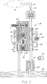
- Figure 1 is a schematic of the hydraulic fluid supply system in an unloaded position, with the directional control valve in the first position.
- FIG. 2 is the schematic of the system of FIG. 1 in an unloaded position with the directional control valve in the second position.
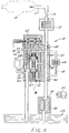
- FIG. 3 is the schematic of the system of FIG. 1 in a loaded position with the directional control valve in the second position.
- FIG. 4 is the schematic of the system of FIG. 1 in a loaded position with the directional control valve in the first position.
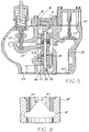
- FIG. 5 is a cross-sectional view of the unloading valve of the invention.
- FIG. 6 is an enlarged, fragmentary, cross-sectional view of the orifice assembly that provides piston damping.
- FIG. 7 is an enlarged, fragmentary, cross-sectional view of an alternate design for providing piston damping.
- FIG. 8 is fragmentary view of the bypass port taken along line 8-8 in FIG. 5.
- FIG. 9 is a fragmentary view of the unloading valve taken along line 9-9 in FIG. 5, wherein the valve is set up for relatively low flow rates.
- FIG. 10 is a fragmentary view of the unloading valve taken along line 10-10 in FIG. 5, wherein the valve is set up for relatively high flow rates.
- FIG. 11 is a chart of flow related settings for set up of the unloading valve.
- FIG. 1 shows a schematic of a hydraulic fluid supply system 18 exemplifying the present invention.
- the supply system 18 shown may be one of a number of such systems in a hydraulic fluid control system.
- An oil pump 20 which is usually powered by a motor 22, supplies high pressure hydraulic fluid from a fluid supply source, such as a sump 24, to a high pressure outlet 25.
- the outlet furnishes hydraulic fluid under pressure to a load, such as an accumulator (shown in dotted lines and designated as 26 in FIGS. 1-4).
- One or more filters 32 may be interposed in the line between the sump 24 and the high pressure load 26 to insure that the hydraulic fluid contains no impurities that would damage the hydraulic system or cause it to malfunction.
- a valve 34 which is in a normally open position when the particular supply system is in use, disposed between the one-way check valve 28 and the high pressure load 26 may be closed when the particular supply system 18 is not being utilized.
- the system 18 may utilize a fixed or variable displacement pump 20 that comes up to speed in a finite time with fluid flow impelled by the pump 20 also increasing during that interval.
- a variable displacement pump 20 is utilized.
- an unloading valve 36 is interposed between the pump 20 and the load 26. While in this example, the one-way check valve 28 is an integral part of the valve 36, it is not necessarily a requirement of the invention.
- the valve 36 includes a valve body 38 having an inlet 40, a working outlet 42, and a bypass outlet 44.
- valve operator 48 such as a piston type valve having a spool 49
- bypass outlet 44 to the sump 24.
- the spool 49 is caused to move axially to close off the bypass port 50 and prevent flow from exiting the valve 36 through the bypass outlet 44, as shown in FIGS. 3 and 4.
- flow entering the valve 36 is forced to exit through the working outlet 42 and the one-way check valve 28 to the high pressure outlet 25.
- the spool 49 is caused to slide axially in the opposite direction, moving the valve operator 48 from the loaded condition shown in FIGS. 3 and 4 to the unloaded position shown in FIGS. 1 and 2, once again allowing flow through the valve 36 via the bypass outlet 44 to the sump 24.
- the pump motor 22 and pump 20 may be stopped without shock to the system. Alternately, the pump 20 may continue to run to circulate the fluid through the unloader valve 36.
- a hydraulic loading system wherein the valve operator is actuated as a result of the flow produced by the pumping system being loaded.
- flow through the unloading valve serves as the activating force for operation of the valve operator.
- the valve could be described accurately as a flow loading unloader valve, but for the sake of simplicity, the invention will be disclosed in terms of an unloading valve.
- the force created due to the flow through the valve to the bypass outlet is derived by a system of passages and controllably applied across the valve operator to move the valve operator from an unloaded to a loaded condition, directing flow to the working outlet.
- the valve may also be designed to unload by appropriately applying the operating force across the valve operator.
- the operating load is redirected to the opposite end of the valve operator so that the high pressure at the inlet causes the spool to return to its unloaded position such that the flow is re-established through the bypass outlet.
- the operating force may also be described in terms of pressure created by the flow from the pump. All other forces being substantially equal, when this pressure, which is applied to one end of the valve operator, is greater than the pressure applied to the opposite end of the valve operator, the valve will move from either the unloaded to the loaded condition, or the loaded to the unloaded condition. While the invention may be described in terms of pressure, it will be appreciated that the invention could likewise be described in terms of forces applied to the valve operator.
- a directional control valve 62 is provided in order to provide a flow connection between the lines 52, 54, 56, 58.
- a solenoid operated four-way valve 62 is utilized to direct the flow to the ends of the valve operator 48. As shown in FIG.
- the solenoid operated valve 62 is in its de-energized position, directing pressure from the inlet 40 through the lines 52 and 54 to the upper end of the spool 49, and also connecting an outlet path from the bypass outlet 44 through the lines 56 and 58 to the lower end of the spool 49.
- a filter 64 is interposed in line 52.
- Line 52 is also provided with a valve 66 that is normally set in the open position.
- valve 36 can likewise operate in a continuous mode, continuously circulating the fluid through the unloading valve 36.
- automatic controls (not shown) sense a low pressure condition in the accumulator tank 26, the controls begin the pumping cycle by energizing the motor 22, which rotates the pump 20 to begin pumping fluid from the sump 24 to the unloading valve 36.
- the electrical solenoid valve 62 is likewise energized to move the valve 62 to its alternate condition, as shown in FIG. 2. It will be appreciated that circuitry may be provided to energize the solenoid valve 62 at approximately the same time as power is supplied to the pump 20.
- the solenoid valve 62 connects the bypass outlet 44 to the upper end of spool 49 by way of lines 56 and 54, and connects the valve inlet 40, and, therefore, the pump outlet 30 to the lower end of the spool 49 by way of lines 52 and 58.
- the spool 49 While the spool 49 travels through a range of positions during operation, it has three equilibrium positions, as illustrated in FIGS. 1-5.
- the spool 49 may be stationary when it is in its extreme downward position, as shown in FIGS. 1 and 2, when it is in its extreme upward, loaded position, as shown in FIGS. 3 and 4, or when it is in its "spring-biased" position, as shown in FIG. 5.
- both of the positions shown in FIGS. 1, 2, and 5, wherein the bypass port 50 is at least partially open may be considered unloaded.
- the spool 49 When the motor 22 first is energized, the spool 49 will be in a spring-biased quiescent condition (as shown in the cross-sectional view of the valve 36 in FIG.
- the load on the pump 20 is greatly reduced and the motor 22 can be stopped to shut down the pump 20.
- the pump 20 can continue to run at a light load until it is indicated that another cycle is required.
- FIG. 5 A cross-sectional view of the unloading valve 36 is shown in more detail in FIG. 5 wherein the components of the valve 36 correspond to those discussed above with reference to the schematics of FIGS. 1-4. While the lines 52, 54, 56, 58 that apply the pressure or operating force across the valve operator 48 are not illustrated in FIG. 5, those connections would be the same as in the schematics of FIGS. 1 through 4.
- the spool 49 is shown in a spring-biased quiescent position, as when there is no flow through the loading valve 36, as before the start of a pumping cycle. When the pumping cycle is initiated and as the pump 20 comes up to speed, the spool 49 rises to block the bypass port 50 to prevent flow to the bypass outlet 44.
- the fluid flows through the working outlet 42 to the high pressure load 26 (not shown in FIG. 5).
- the solenoid operated valve 62 (not shown in FIG. 5) reverses the pressure or operating force across the valve operator 48, the spool 49 moves downward to again allow flow to the bypass outlet 44, which reduces the load on the pump 20 so that it may be de-energized.
- the unloading valve 36 allows smooth transitional loading and unloading by providing smooth, shock-free action during operation.
- One feature that contributes to the safe operation of the unloading valve 36 is a relief valve 66 provided along the outlet side of the valve operator 48. While the relief valve 66 may be set to allow fluid passage at any appropriate pressure, in a preferred embodiment of the invention, the pressure at which the relief valve 66 allows fluid passage may be set in a range between around 200 to 1650 psi. In one unit embodying the invention, the relief valve 66 pressure was preset at 590 psi.
- the spool 49 progressively blocks the bypass flow path through the bypass port 50.
- the pressure of the fluid in the valve 36 increases rapidly as the opening of the bypass port 50 gets progressively smaller. If for some reason the pump outlet pressure rises to a level that is higher than normal (for example, if the valve 34 were inadvertently left closed), and then the valve 36 was loaded, the relief valve 66 would open at a safe level, by passing the fluid to the outlet passage 44.
- the relief valve 66 will continue to allow the passage of fluid to the bypass outlet after the bypass port 50 has been completely blocked by the piston 48, so long as the pressure differential exceeds the preset level of the relief valve 66. In this way, the relief valve 66 provides a safety feature by preventing pressure within the valve 36 from exceeding desired operating levels.
- an orifice assembly 68 is provided.
- an orifice assembly 68 is disposed to control the flow of fluid to and from the upper end of the valve operator 48 as directed by the solenoid operated directional valve 62.
- the orifice assembly 68 includes a first relatively large orifice 70 and a second relatively small orifice 72 to control the rate at which fluid flows from or is supplied to the upper end of the valve operator 48. While the orifice assembly 68 is not shown in FIG.
- the assembly 68 is disposed to regulate flow to and from the chamber at the upper end of the valve operator 48.
- the orifice assembly 68 lies in a plane approximately 30° from the front plane of the cross-sectional view shown in FIG. 5, although the orifice assembly 68 may be disposed at any appropriate angle to facilitate the required hydraulic connections.
- the small orifice 72 is disposed such that it opens at one end into the lip 74 in the valve body 38 in which an o-ring 76 is seated and at the other end to the large orifice 70, although the small orifice 72 could likewise be disposed parallel to the large orifice 70, opening into the line 54 as shown schematically in FIGS. 1-4.
- the large orifice 70 provides flow from the chamber above the valve operator 48 directly to the line 54.
- the spool 49 moves from the unloaded to the loaded position, fluid flows out of the chamber above the valve operator 48 substantially through the large orifice 70 to line 54 to the directional valve 62 and on to the sump 24.
- the spool 49 moves upward in the chamber, it eventually blocks the opening of the large orifice 70 to prevent flow therethrough.
- the additional fluid displaced by the rising spool 49 must flow through the small orifice 72.
- the orifice assembly 68 functions similar to a shock absorber to prevent rapid movement of the spool 49.
- the spool 49 moves about one third of its travel distance before closing off the large orifice 70 opening.
- the orifice assembly 68 provides smooth loading and unloading of the valve 36 by a damping feature.
- an alternate design such as the orifice 70a and valve operator 48a design shown in FIG. 7, may likewise provide multi-stage damping movement of the spool 49a. Similar to the embodiment shown in FIG. 6, substantial flow of fluid to and from the chamber at the upper end of the valve operator 48a is provided by a relatively large orifice 70a. In this embodiment, the slower, more controlled flow of fluid and movement of the spool 49a is provided by a series of smaller orifices 72a and grooves 73 provided in the spool 49a. These smaller orifices 72a and grooves 73 provide additional damping during the final movement of the spool 49a.
- the difference in pressure across the valve operator 48, or differential pressure, at which the spool 49 begins to move is 50 psi, although the valve may be adjusted to provide movement at an alternate pressure.
- This differential pressure is dependant upon the flow rate from the pump 20, as well as the area of the open portion of the bypass port 50.
- ⁇ P the differential pressure in pounds per square inch (lbs/in2)
- Q the flow rate from the pump 20 in cubic inches per second (in3/sec)
- A the area of the open portion of the port 50 in square inches (in2)
- C a constant flow related coefficient that is experimentally determined and is dependent upon the dimensions of the valve 36 and the unloading port 50, among other things:
- Q C
- the value of the constant C is 100.
- the spool 49 will begin to move immediately when the pump 20 is energized to produce a flow of 400 gpm.
- the unloading valve 36 may be adjusted to accommodate a wide range of flow capacities and pressures, and still provide movement of the spool 49 at the requisite 50 psi differential pressure, or at a different pressure for a different flow rate if so desired.
- the flow capacity for the valve 36 is the range between 10 gallons per minute and 400 gallons per minute.
- the same valve 36 can be configured to be fully functional in a small system where design flow rates are only 10 gpm, or in a substantially larger system where flow rates of 400 gpm are accommodated.
- the valve 36 can accommodate a corresponding wide range of pressures.
- the valve 36 can accommodate pressures ranging from about 150 psi to 1100 psi, or, in some cases, as high as 1650 psi. In accomplishing these features such that a single valve 36 may be configured to operate over a range of pressures and flow rates, no major mechanical changes in the valve body 38 itself as well as changes in various components utilized in the valve 36 are required. Rather, in order to configure a valve 36 that operates over a particular range of flow rates or pressures, the valve 36 has a number of possible initial setups.
- the valve 36 may be set up so that the open area of the port 50 is of the appropriate size, as determined by solving for A in the above equation, to result in spool 49 movement at 50 psi or other desired differential pressure for a given flow rate.
- the invention provides a particularly shaped port 50 design as well as means to adjust the extent to which the bypass port 50 will open during maximum flow through the unloading valve 36.
- the port 50 has a shape that is particularly suited for passing a range of flows.
- the bypass port 50 which is shown in FIG. 8 has a large, substantially rectangular-shaped lower portion 80, and a substantially triangular-shaped upper portion 82. It will be appreciated that the level of fluid flow from the pump 20, along with the differential pressure desired will determine how much of the port 50 will open to bypass flow when the piston 48 is in the spring-biased position. For example, at high flow levels, substantial fluid flow will be provided through both the large lower portion 80 and the shaped upper portion 82.
- bypass port 50 provides smooth, shock-free transitional loading and unloading operations. It will be appreciated that this particular port 50 shape is given by way of example, and that the port 50 may be of an alternate shape that likewise provides smooth transitional loading and unloading.
- the distance that the unloader spool 49 is permitted to travel is limited by a system of centering springs 84, 86 and spacers 88, 90.
- the number of spacers, in this embodiment washers 88, 90 are used, and the spring 84, 86 biased gap A may be adjusted at initial setup of the valve 36.
- the initial, adjustable start-up differential pressure for a given flow rate is determined by the set up of the springs 84, 86 and washers 88, 90.
- a differential pressure of approximately 50 psi provides for fast initial loading action from a pump 20 unloaded condition, although it will be appreciated that the valve 36 may be set up to operate at an alternate differential pressure as desired.
- the adjustability of the unloader valve operator spool 49 biasing along with the particular shape of the bypass port 50 combine to provide a valve 36 that will operate over a wide flow range and pressure range.
- the range of flow rates may be adjusted by the extent to which the bypass port 50 is uncovered by the spool 49.
- the unloader valve operator spool 49 may be set up to close off all of the large rectangular portion 80 of the bypass port 50, as shown in FIG. 9. In this way, the bypass flow is restricted to the triangular portion 82 of the port 50, which will generate the requisite pressure drop across the unloader valve operator 48 at a low flow rate.
- the spool 49 may be set up to allow the opening of a large portion of the rectangular-shaped port 80 as shown in FIG. 10. This allows a higher bypass flow rate to generate the same pressure drop across the valve 36.
- FIG. 11 A chart of representative flow related settings for the setup of the valve 36 in a preferred embodiment are shown in the chart identified as FIG. 11. It will be appreciated that the values given are by way of representation and not limitation. As shown in the chart, for a given flow rate in gallons per minute (gpm), a specified number of washers 88, 90 may be assembled with the unloader piston to achieve the specified gap identified as A in FIG. 5. Gap A represents the distance between the lower surface of the unloader valve operator spool 49 in its quiescent spring-biased position and a reference point, which is the lower surface of the valve body 38 in this embodiment. As shown in the chart of the FIG. 11, for low flow rate, such as 10-50 gallons per minute, the gap A is relatively large.
- valve 36 may be set up to provide a desired differential pressure across the valve 36 for either high or low flow rates, as shown in the chart.
- Each of the representative flow related setups shown in FIG. 11 will provide a 50 psi differential pressure for the given flow rates.
- the valve 36 may be adjusted to provide a second differential pressure by adjusting a stop to establish a minimum lower position for the unloader valve operator spool 49 when the valve 36 is operating in an unloaded condition.
- This stop includes a threaded rod 94, which extends through the spool 49.
- the lower bolt head 96 on the threaded rod 94 may be rotated to thread the rod 94 through the spool 49 and the upper bolt 98.
- the downward movement of the spool 49 will be limited when the lower bolt head 96 and the threaded rod 94 reach the base plate 86 of the valve 36, as shown in FIG. 5.
- This second differential pressure is especially useful to avoid oil heating problems when the pump 20 is being run continuously, for example in flow ranges of 10-400 gallons per minute. In this way, a low but controlled pressure drop may be established across the valve 36 when the pump 20 is running substantially unloaded during much of a continuous operating mode. Operation of the valve 36 using this second differential pressure as a temperature and viscosity control device is disclosed in more detail in the copending application serial no. 602,712.
- the invention provides an unloading valve 36 that is interposed between the pump 20 and a high pressure load 26.
- the valve controllably imposes a hydraulic load on the pump 20 at start up and releases the load before the pump 20 shuts down at the end of a cycle.
- the valve 36 includes an inlet 40, a working outlet 42, a bypass outlet 44, and a valve operator 48, which controls the direction of flow through the valve 36.
- the movement of the valve operator spool 49 which is interposed between the inlet 40 and the bypass outlet 44, is achieved by applying the differential pressure created across the valve 36 to the spool 49.
- valve 36 is suitable for a wide range of flow rates and pressures, and may be adjusted to provide a desired pressure differential across the valve 36 by adjusting the degree to which the valve operator 48 allows flow through the bypass port 50 when the valve 36 is in the unloaded condition.
- the valve 36 further includes a pressure relief valve 66, which operates to prevent an over pressure situation.
- the invention provides a valve 36 having hydraulic connections to only the sump 24, the high pressure load 26, and a source of fluid, such as the pump 20, wherein the valve 36 may be operated in both cyclic and continuous modes, and further prevents a situation in which there is excessive pressure build up in the system 18.
Landscapes
- Engineering & Computer Science (AREA)
- Mechanical Engineering (AREA)
- General Engineering & Computer Science (AREA)
- Physics & Mathematics (AREA)
- Fluid Mechanics (AREA)
- Safety Valves (AREA)
- Fluid-Pressure Circuits (AREA)
Applications Claiming Priority (2)
| Application Number | Priority Date | Filing Date | Title |
|---|---|---|---|
| US07/602,717 US5156177A (en) | 1990-10-24 | 1990-10-24 | Flow loading unloader valve |
| US602717 | 1990-10-24 |
Publications (1)
| Publication Number | Publication Date |
|---|---|
| EP0484049A1 true EP0484049A1 (en) | 1992-05-06 |
Family
ID=24412521
Family Applications (1)
| Application Number | Title | Priority Date | Filing Date |
|---|---|---|---|
| EP19910309834 Withdrawn EP0484049A1 (en) | 1990-10-24 | 1991-10-24 | Flow loading unloader valve |
Country Status (3)
| Country | Link |
|---|---|
| US (1) | US5156177A (no) |
| EP (1) | EP0484049A1 (no) |
| NO (1) | NO914168L (no) |
Families Citing this family (8)
| Publication number | Priority date | Publication date | Assignee | Title |
|---|---|---|---|---|
| US5348450A (en) * | 1993-06-09 | 1994-09-20 | Ingersoll-Rand Company | Bootstrap method of loading a compressor having a spring loaded blowoff valve |
| US5535773A (en) * | 1994-09-28 | 1996-07-16 | Hr Textron Inc. | Hydromechanical differentiating apparatus |
| US6604910B1 (en) | 2001-04-24 | 2003-08-12 | Cdx Gas, Llc | Fluid controlled pumping system and method |
| US6497556B2 (en) * | 2001-04-24 | 2002-12-24 | Cdx Gas, Llc | Fluid level control for a downhole well pumping system |
| KR100451651B1 (ko) * | 2001-12-13 | 2004-10-08 | 엘지전자 주식회사 | 원심형 압축기의 역회전 방지구조 |
| US6769880B1 (en) * | 2002-09-19 | 2004-08-03 | Mangonel Corporation | Pressure blowdown system for oil injected rotary screw air compressor |
| US8607559B2 (en) * | 2009-12-29 | 2013-12-17 | Eaton Corporation | Fluid bypass system |
| US10041506B2 (en) | 2015-06-30 | 2018-08-07 | General Electric Company | System for discharging compressed air from a compressor |
Citations (3)
| Publication number | Priority date | Publication date | Assignee | Title |
|---|---|---|---|---|
| FR2231250A5 (no) * | 1973-05-25 | 1974-12-20 | Bosch Gmbh Robert | |
| JPS5551104A (en) * | 1978-10-02 | 1980-04-14 | Diesel Kiki Co Ltd | Solenoid operated selector valve |
| GB2056628A (en) * | 1979-08-10 | 1981-03-18 | Bosch Gmbh Robert | Pressure valve |
Family Cites Families (27)
| Publication number | Priority date | Publication date | Assignee | Title |
|---|---|---|---|---|
| GB229147A (en) * | 1924-05-03 | 1925-02-19 | Babcock & Wilcox Ltd | Improvements relating to safety valves |
| US2125949A (en) * | 1934-11-08 | 1938-08-09 | Smoot Engineering Corp | Regulator |
| US2135949A (en) | 1937-06-17 | 1938-11-08 | Rca Corp | Noise suppressor circuit |
| US2982217A (en) * | 1956-12-26 | 1961-05-02 | Thompson Ramo Wooldridge Inc | Pump and accumulator unloader assembly |
| US3024732A (en) * | 1957-02-01 | 1962-03-13 | Sargent Engineering Corp | Regulating valve |
| US3119550A (en) * | 1961-02-09 | 1964-01-28 | Carrier Corp | Compressor capacity control |
| DE1154320B (de) * | 1961-08-02 | 1963-09-12 | Teves Kg Alfred | Ventil zum Aufladen hydraulischer oder pneumatischer Speicher im Nebenschluss |
| US3524465A (en) * | 1968-09-03 | 1970-08-18 | Hypro Inc | Unloader valve assembly |
| US3723025A (en) * | 1970-10-23 | 1973-03-27 | Abex Corp | Variable bypass for fluid power transfer systems |
| US3692038A (en) * | 1971-04-08 | 1972-09-19 | Danfoss As | Device for venting oil pumps |
| US3884253A (en) * | 1971-12-29 | 1975-05-20 | Kayaba Industry Co Ltd | Hydraulic control valve |
| US4276810A (en) * | 1972-11-08 | 1981-07-07 | Control Concepts, Inc. | Programmed valve system used for positioning control |
| US4202250A (en) * | 1975-05-16 | 1980-05-13 | Control Concepts, Inc. | Programmed unbalanced load valve system |
| US3942548A (en) * | 1972-12-29 | 1976-03-09 | Kayabakogyokabushikikaisha | Fluid control valve |
| US3955396A (en) * | 1974-10-11 | 1976-05-11 | Gulf & Western Manufacturing Company | Press overload protection system |
| US4015620A (en) * | 1974-10-11 | 1977-04-05 | Gulf & Western Manufacturing Company | High response unloading valve |
| DE2533164C3 (de) * | 1975-07-24 | 1982-02-11 | International Harvester Company Mbh, 4040 Neuss | Hydraulische Steuereinrichtung für ein Hydrauliksystem |
| US3977102A (en) * | 1975-10-31 | 1976-08-31 | Caterpillar Tractor Co. | Load ejection improvement for auger scrapers |
| USRE30127E (en) * | 1975-10-31 | 1979-10-30 | Caterpillar Tractor Co. | Load ejection improvement for self-loading scrapers |
| JPS5393265A (en) * | 1977-01-26 | 1978-08-16 | Girling Ltd | System of hydraulic pressure |
| US4171708A (en) * | 1977-04-25 | 1979-10-23 | Lear Siegler, Inc. | Bypass and unloader valve |
| US4172466A (en) * | 1977-07-01 | 1979-10-30 | Target Rock Corporation | Self-actuated pilot-controlled safety valve |
| US4292990A (en) * | 1980-02-07 | 1981-10-06 | Lear Siegler, Inc. | High pressure unloader valve |
| DE3272593D1 (en) * | 1981-09-26 | 1986-09-18 | Barmag Barmer Maschf | Electro-hydraulic pilot-operated proportional throttle valve |
| US4418709A (en) * | 1981-11-19 | 1983-12-06 | J. I. Case Company | Unloading valve for hi-lo-hydraulic system |
| US4569372A (en) * | 1984-08-28 | 1986-02-11 | Commercial Shearing, Inc. | Remote valve operators |
| US4730543A (en) * | 1985-06-17 | 1988-03-15 | Hi-Ranger, Inc. | Closed center hydraulic valve control system for aerial lift |
-
1990
- 1990-10-24 US US07/602,717 patent/US5156177A/en not_active Expired - Lifetime
-
1991
- 1991-10-23 NO NO91914168A patent/NO914168L/no unknown
- 1991-10-24 EP EP19910309834 patent/EP0484049A1/en not_active Withdrawn
Patent Citations (3)
| Publication number | Priority date | Publication date | Assignee | Title |
|---|---|---|---|---|
| FR2231250A5 (no) * | 1973-05-25 | 1974-12-20 | Bosch Gmbh Robert | |
| JPS5551104A (en) * | 1978-10-02 | 1980-04-14 | Diesel Kiki Co Ltd | Solenoid operated selector valve |
| GB2056628A (en) * | 1979-08-10 | 1981-03-18 | Bosch Gmbh Robert | Pressure valve |
Non-Patent Citations (1)
| Title |
|---|
| PATENT ABSTRACTS OF JAPAN vol. 4, no. 94 (M-19)8 July 1980 & JP-A-55 051 104 ( KAWASAKI ) 14 April 1980 * |
Also Published As
| Publication number | Publication date |
|---|---|
| US5156177A (en) | 1992-10-20 |
| NO914168D0 (no) | 1991-10-23 |
| NO914168L (no) | 1992-04-27 |
Similar Documents
| Publication | Publication Date | Title |
|---|---|---|
| JP2923379B2 (ja) | 水圧モータ制御装置 | |
| EP0249154B1 (en) | Hydraulic pressure system | |
| US4401009A (en) | Closed center programmed valve system with load sense | |
| CN100447466C (zh) | 压力补油阀 | |
| US4383412A (en) | Multiple pump load sensing system | |
| KR20090074059A (ko) | 펌프 출력 압력 제어용 제어 시스템 및 제어 방법 | |
| US2489435A (en) | Power transmission | |
| CA2963197A1 (en) | Three-way pressure control and flow regulator valve | |
| US5156177A (en) | Flow loading unloader valve | |
| US5490539A (en) | Pressure regulator for maintaining a stable flow level of a fluid | |
| US5215444A (en) | System for controlling oil viscosity and cleanliness | |
| US4119016A (en) | Hydraulic control device | |
| SE443409B (sv) | Ventilanordning for styrning av funktionen hos en hydraulmotor | |
| CZ280875B6 (cs) | Regulační systém hydraulického výtahu | |
| DE4136396A1 (de) | Hydrauliksystem fuer ein fahrzeug | |
| EP0109220B1 (en) | Improvements in or relating to the control of fluid pressure circuits | |
| US3091929A (en) | Regenerative hydraulic circuit | |
| JPS63282071A (ja) | 油圧式エレベータ駆動制御系 | |
| JP4088606B2 (ja) | 建設重装備用流量制御装置 | |
| US4345736A (en) | Solenoid operated valve and dashpot assembly | |
| US3597921A (en) | Priority flow control valve | |
| US4609330A (en) | Modular unloading sequencing switching valve assembly for hydraulic system | |
| EP4148014B1 (en) | Device for controlled re-entry of a cylinder | |
| US5097745A (en) | Speed control valve for a hydraulic motor speed controlled by pressure between throttle and motor | |
| KR102938365B1 (ko) | 유압 시스템의 압력 한도 제어를 위한 동적 논리 소자 |
Legal Events
| Date | Code | Title | Description |
|---|---|---|---|
| PUAI | Public reference made under article 153(3) epc to a published international application that has entered the european phase |
Free format text: ORIGINAL CODE: 0009012 |
|
| AK | Designated contracting states |
Kind code of ref document: A1 Designated state(s): AT DE ES FR GB IT |
|
| STAA | Information on the status of an ep patent application or granted ep patent |
Free format text: STATUS: THE APPLICATION IS DEEMED TO BE WITHDRAWN |
|
| 18D | Application deemed to be withdrawn |
Effective date: 19921107 |