EP0484052A1 - Datenübertragungseinheit mit mehreren Auschlussstellen - Google Patents
Datenübertragungseinheit mit mehreren Auschlussstellen Download PDFInfo
- Publication number
- EP0484052A1 EP0484052A1 EP91309844A EP91309844A EP0484052A1 EP 0484052 A1 EP0484052 A1 EP 0484052A1 EP 91309844 A EP91309844 A EP 91309844A EP 91309844 A EP91309844 A EP 91309844A EP 0484052 A1 EP0484052 A1 EP 0484052A1
- Authority
- EP
- European Patent Office
- Prior art keywords
- data transmission
- ports
- transmission unit
- data
- received
- Prior art date
- Legal status (The legal status is an assumption and is not a legal conclusion. Google has not performed a legal analysis and makes no representation as to the accuracy of the status listed.)
- Granted
Links
Images



Classifications
-
- H—ELECTRICITY
- H04—ELECTRIC COMMUNICATION TECHNIQUE
- H04M—TELEPHONIC COMMUNICATION
- H04M11/00—Telephonic communication systems specially adapted for combination with other electrical systems
- H04M11/06—Simultaneous speech and data transmission, e.g. telegraphic transmission over the same conductors
Definitions
- the present invention generally relates to data transmission units, and more particularly to a data transmission unit which enables the use of one line by a plurality of terminals.
- the switched line may employ the 2-wire half duplex communication system or the 2-wire full duplex communication system. Regardless of which one of these communication systems is employed, there is an increased demand to support a plurality of terminals by a single data transmission unit.
- FIG.1 shows an example of a conventional switched line modem.
- a modem 3 only has one terminal connection port. For this reason, a plurality of terminals, that is, two terminals 2a and 2b in this case, cannot be connected directly to the modem 3.
- a switch 4 is coupled between the modem 3 and the terminals 2a and 2b. This switch 4 is used to switch the modem interface manually.
- each terminal must be coupled to an independent modem as shown in FIG.2.
- the terminal 2a is coupled to the switch 4 via a modem 3a
- the terminal 2b is coupled to the switch via a modem 3b which employs a transmission mode different from that employed by the modem 3a.
- the switch 4 must be switched manually and it is troublesome to carry out such a manual switching.
- the modem 3 has a plurality of transmission modes such as the 2-wire full duplex and 2-wire half duplex communication modes, it is necessary not only to switch the modem interface but also recognize the set transmission mode of the modem 3 so that the modem setting may be changed to the appropriate transmission mode if necessary.
- the switch 4 must be switched manually and it is troublesome to carry out such a manual switching.
- Another and more specific object of the present invention is to provide a data transmission unit comprising a plurality of ports, where each of the ports is connected to one of a plurality of terminals, data transmission controller means, connected to a line, for controlling a data transmission, and control means, coupled between the data transmission controller and the ports, for exchanging data between one of the ports and the data transmission controller means in response to a call out command which is received from one of the terminals via the one of the ports.
- the data transmission unit of the present invention it is possible to use a single data transmission controller means in common by a plurality if terminals, and the transmission mode of the data transmission controller means can be set automatically even if the data transmission controller means has a plurality of transmission modes, without the need for a manual switching operation.
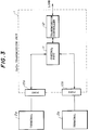
- a data transmission unit 1 includes a plurality of ports 10a and 10b, a control part 11 and a data transmission controller 12 which are connected as shown.
- a terminal 2a is coupled to the port 10a, and a terminal 2b is coupled to the port 10b.
- the data transmission controller 12 is connected to a line.
- the data transmission controller 12 controls the data transmission.
- the control part 11 exchanges data between one of the terminals 10a and 10b and the data transmission controller 12 in response to a call command from one of the terminals 10a and 10b.
- the control part 11 may send a busy answer to the terminal 2a which generated the call command.
- the plurality of ports 10a and 10b are automatically switched by the control part 11 in response to the call command. For this reason, the troublesome manual switching of the modem interface is unnecessary, and the single data transmission controller 12 may be used in common by the plurality of terminals 10a and 10b.
- the terminal 2a receives the busy answer even when the terminal 2a makes an automatic calling. Hence, the terminal 2a will not hang up and may carry out a next process such as a redialing process.
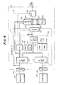
- FIG.4 a description will be given of a first embodiment of a data transmission unit according to the present invention, by referring to FIG.4.
- FIG.4 those parts which are the same as those corresponding parts in FIG.3 are designated by the same reference numerals, and a description thereof will be omitted.
- the ports 10a and 10b are modem interfaces for respectively coupling to the terminals 2a and 2b.
- the port 10a is coupled to a serial interface circuit 110 and a switching circuit 11b
- the port 10b is coupled to a serial interface circuit 111 and the switching circuit 11b.
- a connection controller 11a analyzes commands from the ports 10a and 10b, and controls the switching circuit 11b and the like.
- the connection controller 11a and the switching circuit 11b form the control part 11.
- the connection controller 11a includes the serial interface circuits 110 and 111, a central processing unit (CPU) 112, a read only memory (ROM) 113, a random access memory (RAM) 114, a memory 115 and a serial interface circuit 116 which are coupled via a bus 119.
- the serial interface circuits 110 and 111 respectively receive the serial data from the ports 10a and 10b and supply the data to the CPU 112 in the form of parallel data.
- the serial interface circuits 110 and 111 respectively convert parallel data received from the CPU 112 into serial data and supply the serial data to the ports 10a and 10b.
- the serial interface circuits 110 and 111 operate independently of each other. Hence, the serial interface circuits 110 and 111 may operate at mutually different transmission speeds and with mutually different data formats. For example, it is possible to operate the port 10a in an asynchronous mode at 2400 dps and operate the port 10b in a synchronous mode at 4800 dps.
- the CPU 112 carries out analysis and setting of the commands received from the ports 10a and 10b, and controls the serial interface circuits 110, 111 and 116. In addition, the CPU 112 controls a network control unit (NCU) 12b and controls the switching of the switching circuit 11b. During a data communication, the CPU 112 can also make a data error correction and a data compression.
- NCU network control unit
- the ROM 113 stores programs of the CPU 112, tables and the like.
- the RAM 114 stores various data.
- the memory 115 is made up of a memory part 115a which is provided with respect to the port 10a and a memory part 115b which is provided with respect to the port 10b.
- the memory part 115a stores data transfer mode setting information from the terminal 2a
- the memory part 115b stores data transfer mode setting information from the terminal 2b.
- the serial interface circuit 116 converts the parallel data from the CPU 112 into serial data, and transmits the serial data to a modem 12a.
- the serial interface circuit 116 also converts serial data from the modem 12a into parallel data and supplies the parallel data to the CPU 112. In a mode in which the error correction and the data compression are made during the data communication, the serial interface circuit 116 functions as the interface between the CPU 112 and the modem 12a.
- the switching circuit 11b switches the interfaces with respect to the modem 12a.
- the switching circuit 11b couples one of the interfaces of the ports 10a and 10b and the CPU 112 to the modem 12a under the control of the CPU 112.
- the modem 12a includes a digital signal processor (DSP) 120 for carrying out the modulation and demodulation digitally, a digital-to-analog (D/A) converter 121 which is used for the transmission, an analog-to-digital (A/D) converter 122 which is used for the reception, and filters 123 and 124 for controlling the band.
- the modem 12a can operate at any one of a plurality of modes.
- the plurality of modes may include the CCITT Recommendations V22bis 2-wire full duplex mode at 2400 bps, the V22 2-wire full duplex mode at 1200 bps, the V.27ter 2-wire half duplex mode at 4800 bps, the V.26bis 2-wire half duplex mode at 2400 bps and the like.
- the NCU 12b is connected to a telephone line, and carries out call out operation and a call in operation.
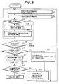
- FIG.5 shows the operations of the CPU 112.
- the CPU 112 constantly monitors the commands from the terminals 2a and 2b in a step S1, and the received command is analyzed in a step S2.
- a step S3 decides whether or not the command received from the terminal is a set command which does not operate the modem 12a and the NCU 12b. If the decision result in the step S3 is YES, a step S4 writes the setting information in the memory 115, and a step S5 returns an indication to the terminal to notify the terminal that the setting information has been written. The process returns to the step S1 after the step S5.
- the ports 10a and 10b may be set independently of each other.
- the modem 12a when viewed from the terminals 2a and 2b, the modem 12a can be made to appear as if the modem 12a is provided exclusively for each of the terminals 2a and 2b.
- a step S6 decides whether or not the command received from the terminal is a call out command. If the decision result is YES, a step S7 decides whether or not at least one of the modem 12a and the NCU 12b is in use. If at least one of the NCU 12b and the modem 12a is used by the port which is other than the port from which the call out command is received and the decision result in the step S7 is YES, a step S8 returns a busy answer to the port from which the call out command is received so as to notify the terminal that the modem 12a is in use. The process returns to the step S1 after the step S8.
- the busy answer may be BUSY in the case of the AT command and CFIAB in the case of the CCITT Recommendations V25bis.
- the decision result in the step S7 is NO, it is judged that an error has occurred and the process returns to the step S1.
- a step S9 supplies the setting information stored in the memory 115 to the modem 12a via the bus 119, so as to set the mode of the modem 12a. Then, a step S10 instructs the NCU 12b to carry out a call out operation, and a step S11 decides whether or not a connection is completed. If the decision result in the step S11 is NO, a step S12 an indication such as the busy answer is returned to the port from which the call out command was received, and the process returns to the step S1.
- a step S13 controls the switching circuit 11b so as to connect the interface of the port from which the call out command was received to the modem 12a and realize an online mode.
- the CPU 112 carries out the error correction and the data compression during the online mode. If this mode is set, the CPU 112 connects the switching circuit 11b to the serial interface circuit 116. Hence, the data from the port 10a or 10b is processed and transmitted to the modem 12a via the serial interface circuit 116.
- a mode may be set from the terminal by a command or the like.
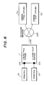
- the single data transmission unit 1 has a 2-wire full duplex mode and a 2-wire half duplex mode.
- the terminal 2a is connected to the port 10a of the data transmission unit 1, and the terminal 2b is connected to the port 10b of the data transmission unit 1.
- the data transmission unit 1 is coupled to a full duplex center 5a and a half duplex center 5b via a line which connects to a switching network 500. Accordingly, the terminals 2a and 2b can communicate with either one of the centers 5a and 5b via the data transmission unit 1 and the switching network 500.
- FIG.7 a description will be given of a second embodiment of the data transmission unit according to the present invention, by referring to FIG.7.
- those parts which are the same as those corresponding parts in FIG.4 are designated by the same reference numerals, and a description thereof will be omitted.
- This embodiment differs from the first embodiment in that no serial interface circuit 116 is provided and that the CPU 112 is not provided with the relay transmission and reception function by error correction and data compression.
- the terminals 2a and 2b are coupled directly to the modem 12a from the respective ports 10a and 10b in the online mode.
- FIG.8 a description will be given of a third embodiment of the data transmission unit according to the present invention, by referring to FIG.8.
- FIG.8 those parts which are the same as those corresponding parts in FIG.4 are designated by the same reference numerals, and a description thereof will be omitted.
- This embodiment differs from the first embodiment in that no switching circuit 11b is provided and that the serial interface circuit 116 is connected directly to the modem 12a.
- the control part 11 is made up solely of the modem interface 11a.
- the mode for each of the ports 10a and 10b and the mode of the modem 12a are preset.
- the terminals 2a and 2b respectively assume the online mode always via the CPU 112.
- the operations of the CPU 112 in the second and third embodiments are basically the same as that shown in FIG.5, and a description thereof will be omitted.
- FIG.9 a description will be given of a fourth embodiment of the data transmission unit according to the present invention, by referring to FIG.9.
- those parts which are the same as those corresponding parts in FIG.8 are designated by the same reference numerals, and a description thereof will be omitted.
- the modes of the ports 10a and 10b and the mode of the modem 12a are preset from an operation panel 900 which is provided on the data transmission unit 1, and the preset information from the operation panel 900 are supplied to the CPU 112.
- the CPU 112 sets the modes of the ports 10a and 10b and the mode of the modem 12a.
- FIG.10 shows an essential part of the operation panel 900.
- FIG.10 shows a display part of the operation panel 900 together with selection buttons 900A, 900B and 900C.
- the selection button 900A is used to select the mode of a port A, a port B or both ports A and B, and one of displays "A", “B” and “A&B” is turned ON when selected. The selection changes from top to bottom every time the selection button 900A is pushed once. The selection is made similarly by the selection buttons 900B and 900C.
- the selection button 900B is used to select one of full duplex mode with 2400 bps, full duplex mode with 1200 bps, half duplex mode with 4800 bps and half duplex mode with 2400 bps.
- the selection button 900C is used to select with the synchronous or asynchronous mode for each of the full and half duplex mode selected by the selection button 900B.
- the terminals 2a and 2b have mutually different modes, namely, the 2-wire full duplex mode and the 2-wire half duplex mode.
- the terminals 2a and 2b may both have the 2-wire full duplex mode or the 2-wire half duplex mode.
- more than two terminals may be connected to the single data communication unit.
Landscapes
- Engineering & Computer Science (AREA)
- Computer Networks & Wireless Communication (AREA)
- Signal Processing (AREA)
- Communication Control (AREA)
Applications Claiming Priority (2)
| Application Number | Priority Date | Filing Date | Title |
|---|---|---|---|
| JP291078/90 | 1990-10-29 | ||
| JP2291078A JPH04167648A (ja) | 1990-10-29 | 1990-10-29 | データ伝送装置 |
Publications (2)
| Publication Number | Publication Date |
|---|---|
| EP0484052A1 true EP0484052A1 (de) | 1992-05-06 |
| EP0484052B1 EP0484052B1 (de) | 1996-08-28 |
Family
ID=17764150
Family Applications (1)
| Application Number | Title | Priority Date | Filing Date |
|---|---|---|---|
| EP91309844A Expired - Lifetime EP0484052B1 (de) | 1990-10-29 | 1991-10-24 | Datenübertragungseinheit mit mehreren Auschlussstellen |
Country Status (4)
| Country | Link |
|---|---|
| US (1) | US5404351A (de) |
| EP (1) | EP0484052B1 (de) |
| JP (1) | JPH04167648A (de) |
| DE (1) | DE69121667D1 (de) |
Cited By (1)
| Publication number | Priority date | Publication date | Assignee | Title |
|---|---|---|---|---|
| EP1143343A3 (de) * | 1994-09-01 | 2004-10-06 | Fujitsu Limited | Verfahren und Vorrichtung zur Ein-/Ausgabeanforderungsverarbeitung mit einer Mehrzahl von Kanalbussen |
Families Citing this family (7)
| Publication number | Priority date | Publication date | Assignee | Title |
|---|---|---|---|---|
| US5511069A (en) * | 1994-06-30 | 1996-04-23 | Intel Corporation | Method and apparatus for controlling a communication device through a modem processor |
| US5561666A (en) * | 1995-03-06 | 1996-10-01 | International Business Machines Corporation | Apparatus and method for determining operational mode for a station entering a network |
| US6084885A (en) * | 1997-02-26 | 2000-07-04 | Paradyne Corporation | Apparatus and method for DSP sharing using statistical properties of data |
| US6134609A (en) * | 1998-03-31 | 2000-10-17 | Micron Electronics, Inc. | Method for using computer system memory as a modem data buffer by transferring modem I/O data directly to system controller and transferring corresponding system controller data directly to main memory |
| US20050025153A1 (en) * | 2002-05-06 | 2005-02-03 | Gordon Bremer | Apparatus and method for asynchronous transfer mode (atm) adaptive time domain duplex (atdd) communication |
| US20040213170A1 (en) * | 2003-04-22 | 2004-10-28 | Gordon Bremer | Extended-performance echo-canceled duplex (EP ECD) communication |
| JP2011145386A (ja) * | 2010-01-13 | 2011-07-28 | Fuji Xerox Co Ltd | 表示制御装置、表示装置及びプログラム |
Citations (3)
| Publication number | Priority date | Publication date | Assignee | Title |
|---|---|---|---|---|
| EP0142302A2 (de) * | 1983-11-03 | 1985-05-22 | AT&T Corp. | Programmierbarer Mehrtyp-Datenmodem |
| GB2187609A (en) * | 1985-12-16 | 1987-09-09 | British Telecomm | Interfacing data units to a telephone line |
| US4718082A (en) * | 1985-09-18 | 1988-01-05 | Ark Electronics | Modem for effecting full duplex asynchronous/synchronous digital data communications over voice grade telephone link |
Family Cites Families (7)
| Publication number | Priority date | Publication date | Assignee | Title |
|---|---|---|---|---|
| JPS5440021A (en) * | 1977-09-06 | 1979-03-28 | Fujitsu Ltd | Multi-port system |
| CA1200036A (en) * | 1978-03-13 | 1986-01-28 | Guido Panizzon | Partyline subscriber interface circuit |
| JPS58204662A (ja) * | 1982-05-24 | 1983-11-29 | Toshiba Corp | デ−タ端末インタ−フエ−ス装置 |
| JPS61140238A (ja) * | 1984-12-13 | 1986-06-27 | Fujitsu Ltd | 通信回線切換方式 |
| JPH01149666A (ja) * | 1987-12-07 | 1989-06-12 | Nippon Telegr & Teleph Corp <Ntt> | セレクタブルマルチポートモデム |
| US4924492A (en) * | 1988-03-22 | 1990-05-08 | American Telephone And Telegraph Company | Method and apparatus for wideband transmission of digital signals between, for example, a telephone central office and customer premises |
| US4893305A (en) * | 1988-03-31 | 1990-01-09 | Racal Data Communications Inc. | Inband dynamic port allocation |
-
1990
- 1990-10-29 JP JP2291078A patent/JPH04167648A/ja active Pending
-
1991
- 1991-10-24 EP EP91309844A patent/EP0484052B1/de not_active Expired - Lifetime
- 1991-10-24 DE DE69121667T patent/DE69121667D1/de not_active Expired - Lifetime
-
1994
- 1994-03-18 US US08/210,721 patent/US5404351A/en not_active Expired - Fee Related
Patent Citations (3)
| Publication number | Priority date | Publication date | Assignee | Title |
|---|---|---|---|---|
| EP0142302A2 (de) * | 1983-11-03 | 1985-05-22 | AT&T Corp. | Programmierbarer Mehrtyp-Datenmodem |
| US4718082A (en) * | 1985-09-18 | 1988-01-05 | Ark Electronics | Modem for effecting full duplex asynchronous/synchronous digital data communications over voice grade telephone link |
| GB2187609A (en) * | 1985-12-16 | 1987-09-09 | British Telecomm | Interfacing data units to a telephone line |
Non-Patent Citations (1)
| Title |
|---|
| PATENT ABSTRACTS OF JAPAN vol. 13, no. 410 (E-819)(3758) 11 September 1989 & JP-1 149 666 ( NTT ) 12 June 1989 * |
Cited By (1)
| Publication number | Priority date | Publication date | Assignee | Title |
|---|---|---|---|---|
| EP1143343A3 (de) * | 1994-09-01 | 2004-10-06 | Fujitsu Limited | Verfahren und Vorrichtung zur Ein-/Ausgabeanforderungsverarbeitung mit einer Mehrzahl von Kanalbussen |
Also Published As
| Publication number | Publication date |
|---|---|
| US5404351A (en) | 1995-04-04 |
| DE69121667D1 (de) | 1996-10-02 |
| JPH04167648A (ja) | 1992-06-15 |
| EP0484052B1 (de) | 1996-08-28 |
Similar Documents
| Publication | Publication Date | Title |
|---|---|---|
| US4991200A (en) | Interface device for the intercommunication of a computer and a fax machine | |
| US4974097A (en) | Data communication apparatus | |
| AU628402B2 (en) | Method of matching operation mode of a modem | |
| AU623939B2 (en) | Modem mode matching by pbx inward dialling | |
| US5003580A (en) | Adapter for interfacing a work station terminal to a key telephone system | |
| US5255312A (en) | Facsimile machine connectable to various communication equipments | |
| US5216705A (en) | Data communication apparatus with an abbreviated dial key having a plurality of dial data and capable of selecting one of two communication functions | |
| US5367564A (en) | Storage-and-forward apparatus | |
| EP0429262B1 (de) | ISDN-Endgerät wirksam mit Durchschaltvermittlungsbetrieb und mit Paketvermittlungsbetrieb | |
| US5404351A (en) | Data transmission unit having a plurality of ports | |
| EP0602948A2 (de) | Verwendung von einer Schnittstelle einer Datenübertragungseinrichtung zum Melden von Halbdaplex- oder Vollduplex-Betrieb | |
| EP0600466B1 (de) | Kommunikationsvorrichtung zum Verbinden von verschiedenen Kommunikationsleitungen | |
| US5410591A (en) | Private branch exchange with resumption of interrupted communication | |
| JPS61200763A (ja) | 複合フアクシミリ装置 | |
| US5166975A (en) | Communication terminal equipment | |
| EP0539964B1 (de) | Modemvorrichtung | |
| KR0149713B1 (ko) | 음성 및 메시지정보 송수신용 통신기기의 모드절환 방법 및 그 장치 | |
| JPH02272856A (ja) | 通信装置 | |
| JPS63128859A (ja) | デ−タ通信装置 | |
| JP2597555B2 (ja) | ディジタル交換システム | |
| US5923442A (en) | Facsimile which controls received data destination and stores or prints the data if the destination is unavailable | |
| JP2513334B2 (ja) | ボタン電話システム | |
| JP2845442B2 (ja) | Dssコンソール装置 | |
| JP2507717B2 (ja) | 電話端末装置 | |
| JP2925680B2 (ja) | Isdn通信装置 |
Legal Events
| Date | Code | Title | Description |
|---|---|---|---|
| PUAI | Public reference made under article 153(3) epc to a published international application that has entered the european phase |
Free format text: ORIGINAL CODE: 0009012 |
|
| AK | Designated contracting states |
Kind code of ref document: A1 Designated state(s): DE FR GB |
|
| 17P | Request for examination filed |
Effective date: 19920527 |
|
| 17Q | First examination report despatched |
Effective date: 19940607 |
|
| GRAG | Despatch of communication of intention to grant |
Free format text: ORIGINAL CODE: EPIDOS AGRA |
|
| GRAH | Despatch of communication of intention to grant a patent |
Free format text: ORIGINAL CODE: EPIDOS IGRA |
|
| GRAH | Despatch of communication of intention to grant a patent |
Free format text: ORIGINAL CODE: EPIDOS IGRA |
|
| GRAA | (expected) grant |
Free format text: ORIGINAL CODE: 0009210 |
|
| AK | Designated contracting states |
Kind code of ref document: B1 Designated state(s): DE FR GB |
|
| PG25 | Lapsed in a contracting state [announced via postgrant information from national office to epo] |
Ref country code: FR Effective date: 19960828 |
|
| REF | Corresponds to: |
Ref document number: 69121667 Country of ref document: DE Date of ref document: 19961002 |
|
| PG25 | Lapsed in a contracting state [announced via postgrant information from national office to epo] |
Ref country code: DE Effective date: 19961129 |
|
| EN | Fr: translation not filed | ||
| PLBE | No opposition filed within time limit |
Free format text: ORIGINAL CODE: 0009261 |
|
| 26N | No opposition filed | ||
| PGFP | Annual fee paid to national office [announced via postgrant information from national office to epo] |
Ref country code: GB Payment date: 19991020 Year of fee payment: 9 |
|
| PG25 | Lapsed in a contracting state [announced via postgrant information from national office to epo] |
Ref country code: GB Free format text: LAPSE BECAUSE OF NON-PAYMENT OF DUE FEES Effective date: 20001024 |
|
| GBPC | Gb: european patent ceased through non-payment of renewal fee |
Effective date: 20001024 |