EP0484193A1 - Reifgeschützte Wasserzähleranlage - Google Patents
Reifgeschützte Wasserzähleranlage Download PDFInfo
- Publication number
- EP0484193A1 EP0484193A1 EP91402720A EP91402720A EP0484193A1 EP 0484193 A1 EP0484193 A1 EP 0484193A1 EP 91402720 A EP91402720 A EP 91402720A EP 91402720 A EP91402720 A EP 91402720A EP 0484193 A1 EP0484193 A1 EP 0484193A1
- Authority
- EP
- European Patent Office
- Prior art keywords
- insulating material
- envelope
- installation according
- meter
- base
- Prior art date
- Legal status (The legal status is an assumption and is not a legal conclusion. Google has not performed a legal analysis and makes no representation as to the accuracy of the status listed.)
- Granted
Links
- 238000009434 installation Methods 0.000 title claims abstract description 57
- XLYOFNOQVPJJNP-UHFFFAOYSA-N water Substances O XLYOFNOQVPJJNP-UHFFFAOYSA-N 0.000 title claims abstract description 48
- 239000011810 insulating material Substances 0.000 claims abstract description 34
- 239000004033 plastic Substances 0.000 claims description 6
- 229920003023 plastic Polymers 0.000 claims description 6
- 239000000463 material Substances 0.000 claims description 5
- 230000000295 complement effect Effects 0.000 claims description 3
- 230000000717 retained effect Effects 0.000 claims description 2
- 238000007710 freezing Methods 0.000 abstract description 7
- 230000008014 freezing Effects 0.000 abstract description 7
- 238000000034 method Methods 0.000 description 4
- 230000000694 effects Effects 0.000 description 3
- 229920005830 Polyurethane Foam Polymers 0.000 description 2
- 238000004519 manufacturing process Methods 0.000 description 2
- 239000002184 metal Substances 0.000 description 2
- 239000011496 polyurethane foam Substances 0.000 description 2
- 229910001369 Brass Inorganic materials 0.000 description 1
- 241000238631 Hexapoda Species 0.000 description 1
- 241001508691 Martes zibellina Species 0.000 description 1
- 241001465754 Metazoa Species 0.000 description 1
- 239000004698 Polyethylene Substances 0.000 description 1
- 238000004873 anchoring Methods 0.000 description 1
- 230000004323 axial length Effects 0.000 description 1
- 238000009412 basement excavation Methods 0.000 description 1
- 239000010951 brass Substances 0.000 description 1
- 238000009933 burial Methods 0.000 description 1
- 230000003749 cleanliness Effects 0.000 description 1
- 239000004794 expanded polystyrene Substances 0.000 description 1
- 238000002513 implantation Methods 0.000 description 1
- 239000012212 insulator Substances 0.000 description 1
- 239000007769 metal material Substances 0.000 description 1
- 238000005192 partition Methods 0.000 description 1
- 230000035515 penetration Effects 0.000 description 1
- -1 polyethylene Polymers 0.000 description 1
- 229920000573 polyethylene Polymers 0.000 description 1
- 239000004576 sand Substances 0.000 description 1
- 230000035939 shock Effects 0.000 description 1
- 210000001550 testis Anatomy 0.000 description 1
Images

Classifications
-
- G—PHYSICS
- G01—MEASURING; TESTING
- G01F—MEASURING VOLUME, VOLUME FLOW, MASS FLOW OR LIQUID LEVEL; METERING BY VOLUME
- G01F15/00—Details of, or accessories for, apparatus of groups G01F1/00 - G01F13/00 insofar as such details or appliances are not adapted to particular types of such apparatus
- G01F15/10—Preventing damage by freezing or excess pressure or insufficient pressure
-
- E—FIXED CONSTRUCTIONS
- E03—WATER SUPPLY; SEWERAGE
- E03B—INSTALLATIONS OR METHODS FOR OBTAINING, COLLECTING, OR DISTRIBUTING WATER
- E03B7/00—Water main or service pipe systems
- E03B7/09—Component parts or accessories
- E03B7/10—Devices preventing bursting of pipes by freezing
- E03B7/12—Devices preventing bursting of pipes by freezing by preventing freezing
Definitions
- the present invention relates to a water metering installation protected against the risk of frost.
- the water meter In water metering installations, the water meter is connected to a water inlet pipe and a water outlet pipe buried in the ground.
- the water meter is located either above ground level or in a well, preferably closed at its upper part by a removable buffer allowing access to the meter.
- the meter In the first case, that is to say when the meter is above ground level, it can be protected externally by a housing, tank, or the like which also allows access to the meter.
- thermal bridges remain between the meter and the outside, so that protection against freezing is not total.
- French patent 87 03453 in the name of the applicant describes a water meter pivotally mounted on a base comprising two water passages connected respectively to the water inlet and outlet pipes.
- the opening and closing of the water supply is controlled by rotating the meter with respect to the base to bring the water passages from the base in coincidence with those of the meter or for set them aside.
- the aim of the present invention is to remedy the drawbacks of known embodiments, by proposing a water metering installation which is both convenient to use, easy to install in the ground and effectively protected against the risk of frost. .
- the invention thus relates to a water metering installation protected against the risk of frost, comprising a water meter connected to a water inlet pipe and to a water departure pipe, this water meter being mounted on a base in which open said water inlet and outlet pipes, these pipes extending in a trench made in the ground, this installation comprising a casing, essentially of thermally insulating material which surrounds the pipes and is open down.
- this installation is characterized in that the upper part of this envelope has a vertical passage in which is engaged the base of the meter, the latter being fixed directly to the insulating material by means avoiding the creation of a thermal bridge between the base and the exterior, the water meter being situated above the envelope and in that the meter is capped by a cap made of insulating material, the lower edge of which is in contact with the upper part of the insulating material of said envelope .
- the envelope is made essentially of thermally insulating material which continuously surrounds the pipes and the base and thus protects them from freezing.
- the downward opening is made in an area not exposed to frost and at a substantially constant temperature, so that the envelope is maintained by heat exchange through said opening at a substantially constant interior temperature, the temperature at which they are also maintained. the pipes and the base.
- fixing the base directly in the thermally insulating material eliminates the thermal bridges encountered in conventional installations. This makes it possible, for the same efficiency, to reduce the thicknesses of thermally insulating material and thus to reduce the external volume of the installation.
- the water metering installation comprises a water meter 1 connected to a water inlet pipe 2 and to a water outlet pipe 3, for example made of polyethylene .
- the water meter 1 is mounted on a base 4 into which the said water inlet and outlet pipes 2, 3 open.
- These pipes 2, 3 extend into a trench made in the ground and penetrate into the ground at the bottom 5 of this trench.
- the installation comprises an envelope 6 of thermally insulating material forming the base of the installation which surrounds the pipes 2, 3 and is open downwards.
- the upper part 7 of this envelope 6 has a vertical passage 8 in which the base 4 of the meter is engaged.
- This base 4 is fixed directly to the insulating material of the casing 6 by means which will be detailed below avoiding the creation of a thermal bridge between the base 4 and the outside.
- the thickness of insulating material which surrounds the base 4 is greater than the thickness of insulating material which surrounds the pipes 2 and 3.
- the thickness of insulating material which surrounds the means for fixing the base 4 in the insulating material is at least equal to the thickness of insulating material which surrounds the pipes 2 and 3.
- the envelope 6 of thermally insulating material comprises an outer shell 9 molded of rigid plastic material covered on its inner face with a thermally insulating material 10.
- This thermally insulating material 10 is preferably an expanded plastic material, such as a polyurethane foam.
- the counter 1 is capped by a cap 11 made of thermally insulating material of the same kind as that of the envelope 6.
- the lower edge of this cap 11 is in contact with the upper part of the thermally insulating material of the envelope 6.
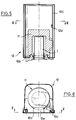
- the insulating cap 11 is itself contained inside a plastic tank 12, the lower edge 12a of which is secured to the upper edge of the insulating envelope 6.
- This tank 12 has a side door 12b.
- the air space 13 surrounding the pipes 2, 3 communicates with the air space 14 between the insulating cap 11 and the counter 1 by air passages 15 formed in the upper wall 7 of the insulating jacket 6.
- the counter 1 is rotatably mounted on the base 4 between an open and closed position of the water inlet.
- This arrangement is known from French patent 87 03453. Consequently, the connection between the insulating cap 11 and the upper part of the insulating casing 6 is adapted to allow rotation of the counter 1 between the two aforementioned positions as well as to allow a disassembly and exchange of said counter 1.
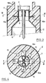
- the attachment between the base 4 and the opening 8 formed in the upper part 7 of the insulating envelope 6 is provided by metal tabs 16a sealed in the insulating material 10 of this envelope.
- the ends of these legs 16a are located at a sufficient distance from the outer face of the envelope 6 to avoid the creation of thermal bridges between the base 4 and the outside.
- the base 4 is made of molded metallic material, for example brass.
- the base includes a central annular tube cooperating with a heat pipe 18 to provide heat transfer. Said tube is integral with two vertical partitions oriented along a diameter and ensuring the mechanical rigidity of the base.
- the lower edge of said flared part 9a has two diametrically opposite openings 17a, 17b for the passage of the water inlet and outlet pipes 2, 3.
- the insulating envelope 6 also surrounds a heat pipe 18 extending vertically between the base 4 and the bottom 5 of the trench dug in the ground.
- This heat pipe 18 penetrates a certain depth into the ground to take calories therefrom and thus maintain the base 4 and the meter at a temperature which minimizes the risk of freezing.
- cap 11 is shaped so as to be able to pivot around an axis 12c, which also allows the opening and pivoting of the door 12b.
- the door 12b opens and pivots 180 ° around the axis 12c.
- Means for retaining the cap 11 in the high position comprise an elastic metal blade 12d.
- the cap 11 When the cap 11 is dislodged by lifting it above the conformations 16b, it can be lifted to a higher position where it will be retained by the flexible blade 12d.
- the blade 12d is pressed so as to allow the cap 11 to slide and descend along the axis 12c.
- the door 12b comprises a means 12e cooperating with the cap 11 to ensure the correct positioning and fitting of the cap 11 on the conformations 16b when the door is closed.
- the means 12e comprises a horizontal rib located just above the upper face of the insulating cap 11 when the cap is fitted and the door closed.
- the rib 12e comes to bear on the top of the cap 11 and prevents the door 12b from closing.
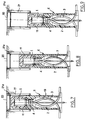
- the installation is completely contained in a well 19 made in the ground, the depth of which is variable.
- the well 19 is closed at its upper part by a buffer 20 allowing access to the meter 1.
- the upper part of the well comprises a sleeve-shaped riser 21 whose upper edge 21a receives the buffer 20.
- the inner surface of the riser 21 is adapted to the outer surface of the casing 6 forming a foot to allow relative sliding between this riser 21 and the casing 6. It is thus possible, as shown in Figures 7, 8 and 9 , to install the installation at variable depths without having to modify the length of the casing 6. It is sufficient for this purpose that the axial length of the riser corresponds at least to the difference between the maximum and minimum depths of the well 19 .
- the continuous insulating material of the casing 6 delimits with the fitted insulating cap 11 a volume of substantially isothermal air without thermal bridge which protects the entire internal hydraulic circuit of the installation from freezing.
- the opening in the lower part of the casing 6 forming a foot in fact allows the exchange with the ground by air convection in the interior volume at the foot and with the interior volume at the cap by the passage 15 provided for this purpose.
- the temperature of said interior volume therefore becomes substantially equal to that prevailing at the depth of burial in the ground, which is constant and generally between 4 ° C and 12 ° C.
- the heat pipe 18 connected to the base 4 reinforces this frost protection effect, by carrying out a heat transfer from a greater depth, therefore at a higher temperature.
- the flaring down of the casing 6 ensures the stability of the installation in the ground by providing good support for the foot and also better resistance to tearing.
- This grid is preferably integral with the installation and mounted in the factory.
Landscapes
- Hydrology & Water Resources (AREA)
- Physics & Mathematics (AREA)
- General Physics & Mathematics (AREA)
- Health & Medical Sciences (AREA)
- Life Sciences & Earth Sciences (AREA)
- Engineering & Computer Science (AREA)
- Water Supply & Treatment (AREA)
- Public Health (AREA)
- Fluid Mechanics (AREA)
- Measuring Volume Flow (AREA)
- Investigating Or Analysing Materials By Optical Means (AREA)
- Pharmaceuticals Containing Other Organic And Inorganic Compounds (AREA)
- Structure And Mechanism Of Cameras (AREA)
- Road Signs Or Road Markings (AREA)
Applications Claiming Priority (2)
| Application Number | Priority Date | Filing Date | Title |
|---|---|---|---|
| FR9013542 | 1990-10-31 | ||
| FR9013542A FR2668594B1 (fr) | 1990-10-31 | 1990-10-31 | Installation de comptage d'eau protegee contre le gel. |
Publications (2)
| Publication Number | Publication Date |
|---|---|
| EP0484193A1 true EP0484193A1 (de) | 1992-05-06 |
| EP0484193B1 EP0484193B1 (de) | 1995-02-22 |
Family
ID=9401756
Family Applications (1)
| Application Number | Title | Priority Date | Filing Date |
|---|---|---|---|
| EP91402720A Expired - Lifetime EP0484193B1 (de) | 1990-10-31 | 1991-10-11 | Reifgeschützte Wasserzähleranlage |
Country Status (7)
| Country | Link |
|---|---|
| EP (1) | EP0484193B1 (de) |
| AT (1) | ATE118877T1 (de) |
| CA (1) | CA2054538A1 (de) |
| DE (2) | DE69107573T2 (de) |
| ES (1) | ES2033593T3 (de) |
| FR (1) | FR2668594B1 (de) |
| GR (1) | GR920300105T1 (de) |
Cited By (3)
| Publication number | Priority date | Publication date | Assignee | Title |
|---|---|---|---|---|
| EP1260799A1 (de) * | 2001-05-23 | 2002-11-27 | Atherm | Abtauvorrichtung für Wasserzähler mit einem Wärmerohr |
| GB2482060A (en) * | 2010-07-13 | 2012-01-18 | John Anthony O'brien | A thermal insulation cover for protecting a stopcock from freezing in the winter |
| CN108894281A (zh) * | 2017-12-19 | 2018-11-27 | 上海熊猫机械(集团)有限公司 | 一种下进出水防冻型智慧集成泵站 |
Families Citing this family (1)
| Publication number | Priority date | Publication date | Assignee | Title |
|---|---|---|---|---|
| DE102017005012A1 (de) * | 2017-05-24 | 2018-11-29 | Linde Aktiengesellschaft | Einfriersicherung |
Citations (2)
| Publication number | Priority date | Publication date | Assignee | Title |
|---|---|---|---|---|
| FR2499293A1 (fr) * | 1981-02-02 | 1982-08-06 | Seperef | Coffret enterre pour la protection d'un compteur |
| FR2606052A1 (fr) * | 1986-10-31 | 1988-05-06 | Cahors App Elec | Dispositif pour supporter et proteger un compteur d'eau a l'egard du gel et son procede d'installation |
-
1990
- 1990-10-31 FR FR9013542A patent/FR2668594B1/fr not_active Expired - Fee Related
-
1991
- 1991-10-11 DE DE69107573T patent/DE69107573T2/de not_active Expired - Fee Related
- 1991-10-11 AT AT91402720T patent/ATE118877T1/de not_active IP Right Cessation
- 1991-10-11 DE DE199191402720T patent/DE484193T1/de active Pending
- 1991-10-11 EP EP91402720A patent/EP0484193B1/de not_active Expired - Lifetime
- 1991-10-11 ES ES91402720T patent/ES2033593T3/es not_active Expired - Lifetime
- 1991-10-30 CA CA002054538A patent/CA2054538A1/en not_active Abandoned
-
1993
- 1993-02-17 GR GR920300105T patent/GR920300105T1/el unknown
Patent Citations (2)
| Publication number | Priority date | Publication date | Assignee | Title |
|---|---|---|---|---|
| FR2499293A1 (fr) * | 1981-02-02 | 1982-08-06 | Seperef | Coffret enterre pour la protection d'un compteur |
| FR2606052A1 (fr) * | 1986-10-31 | 1988-05-06 | Cahors App Elec | Dispositif pour supporter et proteger un compteur d'eau a l'egard du gel et son procede d'installation |
Cited By (5)
| Publication number | Priority date | Publication date | Assignee | Title |
|---|---|---|---|---|
| EP1260799A1 (de) * | 2001-05-23 | 2002-11-27 | Atherm | Abtauvorrichtung für Wasserzähler mit einem Wärmerohr |
| FR2825148A1 (fr) * | 2001-05-23 | 2002-11-29 | Atherm | Dispositif de mise hors gel des compteurs d'eau par caloduc |
| GB2482060A (en) * | 2010-07-13 | 2012-01-18 | John Anthony O'brien | A thermal insulation cover for protecting a stopcock from freezing in the winter |
| GB2482060B (en) * | 2010-07-13 | 2015-08-26 | John Anthony O'brien | An insulating device |
| CN108894281A (zh) * | 2017-12-19 | 2018-11-27 | 上海熊猫机械(集团)有限公司 | 一种下进出水防冻型智慧集成泵站 |
Also Published As
| Publication number | Publication date |
|---|---|
| FR2668594B1 (fr) | 1993-02-12 |
| DE69107573D1 (de) | 1995-03-30 |
| CA2054538A1 (en) | 1992-05-01 |
| DE484193T1 (de) | 1992-11-26 |
| EP0484193B1 (de) | 1995-02-22 |
| FR2668594A1 (fr) | 1992-04-30 |
| DE69107573T2 (de) | 1995-08-03 |
| ES2033593T3 (es) | 1995-05-01 |
| ATE118877T1 (de) | 1995-03-15 |
| ES2033593T1 (es) | 1993-04-01 |
| GR920300105T1 (en) | 1993-02-17 |
Similar Documents
| Publication | Publication Date | Title |
|---|---|---|
| CA1239849A (fr) | Dispositif de protection contre le gel d'installations de stockage ou fourniture de liquide gelif notamment de l'eau | |
| EP0894430B1 (de) | FrostsichereTränke mit gleichbleibendem Flüssigkeitsstand zur Aussenverwendung | |
| EP0484193B1 (de) | Reifgeschützte Wasserzähleranlage | |
| EP0287407B1 (de) | Apparat zur Verbindung und zum Stützen eines Wasserzählers | |
| FR2606052A1 (fr) | Dispositif pour supporter et proteger un compteur d'eau a l'egard du gel et son procede d'installation | |
| CA1270138A (fr) | Couvercle de trou d'homme mobile | |
| FR2483980A1 (fr) | Procede pour la construction d'une maison et maison s'y rapportant | |
| BE1016948A6 (fr) | Siphon de cour (sterfput). | |
| FR2693320A1 (fr) | Boîtier étanche pour protéger les installations électriques. | |
| CA1145572A (fr) | Bague d'egouttage amovible pour puits d'acces ou boyau de ventilation | |
| FR2627664A1 (fr) | Abreuvoir pour animaux | |
| EP3815523B1 (de) | Tiertränke | |
| FR2880239A1 (fr) | Bac a plantes sur pilotis | |
| FR2490449A1 (fr) | Installation modulaire de recuperation de gaz a partir de dechets vegetaux | |
| FR2678969A1 (fr) | Dispositif de protection d'une tuyauterie d'evacuation d'eaux usees d'une habitation contre la penetration des rats d'egout. | |
| FR2732380A1 (fr) | Procede et dispositif pour maintenir en service un drainage d'evacuation pendant une construction de canalisation | |
| FR2601847A1 (fr) | Dispositif de distribution d'eau temperee pour les porcs. | |
| EP0927847A1 (de) | Entlüftung für ein unterirdisches Gehäuse | |
| CH658279A5 (en) | Odour-seal device for a pipeline manhole | |
| FR3060621A1 (fr) | Regard avaloir a tubulure coudee | |
| FR2888592A1 (fr) | Borne d'exterieur abritant un ensemble de comptage | |
| WO2008145887A2 (fr) | Installation d'enneigement et logette pour une telle installation | |
| FR2548544A1 (fr) | Bouche d'incendie a clapet anti-retour | |
| FR3143653A1 (fr) | Dispositif de couverture d'une tête et station de pompage d'un puits de forage | |
| FR2719613A1 (fr) | Dispositif préfabriqué de comptage et de disconnexion destiné à permettre l'installation sur le terrain d'une distribution d'eau et à la raccorder au réseau public. |
Legal Events
| Date | Code | Title | Description |
|---|---|---|---|
| PUAI | Public reference made under article 153(3) epc to a published international application that has entered the european phase |
Free format text: ORIGINAL CODE: 0009012 |
|
| 17P | Request for examination filed |
Effective date: 19911019 |
|
| AK | Designated contracting states |
Kind code of ref document: A1 Designated state(s): AT BE CH DE DK ES FR GB GR IT LI LU NL SE |
|
| GBC | Gb: translation of claims filed (gb section 78(7)/1977) | ||
| ITCL | It: translation for ep claims filed |
Representative=s name: BARZANO' E ZANARDO ROMA S.P.A. |
|
| TCNL | Nl: translation of patent claims filed | ||
| TCAT | At: translation of patent claims filed | ||
| DET | De: translation of patent claims | ||
| 17Q | First examination report despatched |
Effective date: 19940309 |
|
| GRAA | (expected) grant |
Free format text: ORIGINAL CODE: 0009210 |
|
| AK | Designated contracting states |
Kind code of ref document: B1 Designated state(s): AT BE CH DE DK ES FR GB GR IT LI LU NL SE |
|
| PG25 | Lapsed in a contracting state [announced via postgrant information from national office to epo] |
Ref country code: NL Free format text: LAPSE BECAUSE OF NON-PAYMENT OF DUE FEES Effective date: 19950222 Ref country code: GR Free format text: LAPSE BECAUSE OF FAILURE TO SUBMIT A TRANSLATION OF THE DESCRIPTION OR TO PAY THE FEE WITHIN THE PRESCRIBED TIME-LIMIT Effective date: 19950222 Ref country code: DK Effective date: 19950222 |
|
| REF | Corresponds to: |
Ref document number: 118877 Country of ref document: AT Date of ref document: 19950315 Kind code of ref document: T |
|
| REF | Corresponds to: |
Ref document number: 69107573 Country of ref document: DE Date of ref document: 19950330 |
|
| ITF | It: translation for a ep patent filed | ||
| REG | Reference to a national code |
Ref country code: ES Ref legal event code: FG2A Ref document number: 2033593 Country of ref document: ES Kind code of ref document: T3 |
|
| GBT | Gb: translation of ep patent filed (gb section 77(6)(a)/1977) |
Effective date: 19950413 |
|
| PG25 | Lapsed in a contracting state [announced via postgrant information from national office to epo] |
Ref country code: SE Effective date: 19950522 |
|
| NLV1 | Nl: lapsed or annulled due to failure to fulfill the requirements of art. 29p and 29m of the patents act | ||
| PG25 | Lapsed in a contracting state [announced via postgrant information from national office to epo] |
Ref country code: LU Free format text: LAPSE BECAUSE OF NON-PAYMENT OF DUE FEES Effective date: 19951031 |
|
| PLBE | No opposition filed within time limit |
Free format text: ORIGINAL CODE: 0009261 |
|
| STAA | Information on the status of an ep patent application or granted ep patent |
Free format text: STATUS: NO OPPOSITION FILED WITHIN TIME LIMIT |
|
| 26N | No opposition filed | ||
| REG | Reference to a national code |
Ref country code: CH Ref legal event code: NV Representative=s name: BOVARD AG PATENTANWAELTE |
|
| REG | Reference to a national code |
Ref country code: GB Ref legal event code: IF02 |
|
| PGFP | Annual fee paid to national office [announced via postgrant information from national office to epo] |
Ref country code: ES Payment date: 20041116 Year of fee payment: 14 |
|
| PGFP | Annual fee paid to national office [announced via postgrant information from national office to epo] |
Ref country code: BE Payment date: 20050415 Year of fee payment: 14 |
|
| PG25 | Lapsed in a contracting state [announced via postgrant information from national office to epo] |
Ref country code: ES Free format text: LAPSE BECAUSE OF NON-PAYMENT OF DUE FEES Effective date: 20051013 |
|
| PG25 | Lapsed in a contracting state [announced via postgrant information from national office to epo] |
Ref country code: BE Free format text: LAPSE BECAUSE OF NON-PAYMENT OF DUE FEES Effective date: 20051031 |
|
| REG | Reference to a national code |
Ref country code: FR Ref legal event code: TP |
|
| REG | Reference to a national code |
Ref country code: GB Ref legal event code: 732E |
|
| REG | Reference to a national code |
Ref country code: CH Ref legal event code: PUE Owner name: MANUFACTURE D'APPAREILLAGE ELECTRIQUE DE CAHORS S Free format text: MANUFACTURE D'APPAREILLAGE ELECTRIQUE DE CAHORS#BOITE POSTALE 149#CAHORS (FR) -TRANSFER TO- MANUFACTURE D'APPAREILLAGE ELECTRIQUE DE CAHORS SOCIETE PAR ACTIONS SIMPLIFIEE#ZONE INDUSTRIELLE DE REGOURD#46000 CAHORS (FR) |
|
| PGFP | Annual fee paid to national office [announced via postgrant information from national office to epo] |
Ref country code: GB Payment date: 20061011 Year of fee payment: 16 Ref country code: AT Payment date: 20061011 Year of fee payment: 16 |
|
| PGFP | Annual fee paid to national office [announced via postgrant information from national office to epo] |
Ref country code: IT Payment date: 20061031 Year of fee payment: 16 |
|
| REG | Reference to a national code |
Ref country code: ES Ref legal event code: FD2A Effective date: 20051013 |
|
| BERE | Be: lapsed |
Owner name: *MANUFACTURE D'APPAREILLAGE ELECTRIQUE DE CAHORS Effective date: 20051031 |
|
| PGFP | Annual fee paid to national office [announced via postgrant information from national office to epo] |
Ref country code: DE Payment date: 20071004 Year of fee payment: 17 |
|
| PGFP | Annual fee paid to national office [announced via postgrant information from national office to epo] |
Ref country code: CH Payment date: 20071029 Year of fee payment: 17 |
|
| GBPC | Gb: european patent ceased through non-payment of renewal fee |
Effective date: 20071011 |
|
| PG25 | Lapsed in a contracting state [announced via postgrant information from national office to epo] |
Ref country code: AT Free format text: LAPSE BECAUSE OF NON-PAYMENT OF DUE FEES Effective date: 20071011 |
|
| PG25 | Lapsed in a contracting state [announced via postgrant information from national office to epo] |
Ref country code: GB Free format text: LAPSE BECAUSE OF NON-PAYMENT OF DUE FEES Effective date: 20071011 |
|
| REG | Reference to a national code |
Ref country code: CH Ref legal event code: PL |
|
| PG25 | Lapsed in a contracting state [announced via postgrant information from national office to epo] |
Ref country code: DE Free format text: LAPSE BECAUSE OF NON-PAYMENT OF DUE FEES Effective date: 20090501 Ref country code: IT Free format text: LAPSE BECAUSE OF NON-PAYMENT OF DUE FEES Effective date: 20071011 |
|
| PG25 | Lapsed in a contracting state [announced via postgrant information from national office to epo] |
Ref country code: CH Free format text: LAPSE BECAUSE OF NON-PAYMENT OF DUE FEES Effective date: 20081031 Ref country code: LI Free format text: LAPSE BECAUSE OF NON-PAYMENT OF DUE FEES Effective date: 20081031 |
|
| PGFP | Annual fee paid to national office [announced via postgrant information from national office to epo] |
Ref country code: FR Payment date: 20091113 Year of fee payment: 19 |
|
| PG25 | Lapsed in a contracting state [announced via postgrant information from national office to epo] |
Ref country code: FR Free format text: LAPSE BECAUSE OF NON-PAYMENT OF DUE FEES Effective date: 20101102 |
|
| REG | Reference to a national code |
Ref country code: FR Ref legal event code: ST Effective date: 20110630 |