EP0484211A1 - Verfahren und Vorrichtung zum Herstellen von Glasfasern mittels Zentrifugieren un Anwendung von bestimmtem Glas zum Zerfasern - Google Patents
Verfahren und Vorrichtung zum Herstellen von Glasfasern mittels Zentrifugieren un Anwendung von bestimmtem Glas zum Zerfasern Download PDFInfo
- Publication number
- EP0484211A1 EP0484211A1 EP91402850A EP91402850A EP0484211A1 EP 0484211 A1 EP0484211 A1 EP 0484211A1 EP 91402850 A EP91402850 A EP 91402850A EP 91402850 A EP91402850 A EP 91402850A EP 0484211 A1 EP0484211 A1 EP 0484211A1
- Authority
- EP
- European Patent Office
- Prior art keywords
- centrifuge
- fiberizing
- temperature
- fibers
- glass
- Prior art date
- Legal status (The legal status is an assumption and is not a legal conclusion. Google has not performed a legal analysis and makes no representation as to the accuracy of the status listed.)
- Granted
Links
Images
Classifications
-
- C—CHEMISTRY; METALLURGY
- C03—GLASS; MINERAL OR SLAG WOOL
- C03B—MANUFACTURE, SHAPING, OR SUPPLEMENTARY PROCESSES
- C03B37/00—Manufacture or treatment of flakes, fibres, or filaments from softened glass, minerals, or slags
- C03B37/01—Manufacture of glass fibres or filaments
- C03B37/02—Manufacture of glass fibres or filaments by drawing or extruding, e.g. direct drawing of molten glass from nozzles; Cooling fins therefor
- C03B37/03—Drawing means, e.g. drawing drums ; Traction or tensioning devices
-
- C—CHEMISTRY; METALLURGY
- C03—GLASS; MINERAL OR SLAG WOOL
- C03B—MANUFACTURE, SHAPING, OR SUPPLEMENTARY PROCESSES
- C03B37/00—Manufacture or treatment of flakes, fibres, or filaments from softened glass, minerals, or slags
- C03B37/01—Manufacture of glass fibres or filaments
- C03B37/04—Manufacture of glass fibres or filaments by using centrifugal force, e.g. spinning through radial orifices; Construction of the spinner cups therefor
- C03B37/045—Construction of the spinner cups
-
- C—CHEMISTRY; METALLURGY
- C03—GLASS; MINERAL OR SLAG WOOL
- C03B—MANUFACTURE, SHAPING, OR SUPPLEMENTARY PROCESSES
- C03B37/00—Manufacture or treatment of flakes, fibres, or filaments from softened glass, minerals, or slags
- C03B37/01—Manufacture of glass fibres or filaments
- C03B37/04—Manufacture of glass fibres or filaments by using centrifugal force, e.g. spinning through radial orifices; Construction of the spinner cups therefor
- C03B37/047—Selection of materials for the spinner cups
Definitions
- the present invention relates to techniques for producing fibers from a thermoplastic material with a high melting point, for example of the glass or basalt type. More particularly the invention relates to a development in the so-called internal centrifugation fiberizing processes in which the material in the molten state is poured into a centrifuge rotating at high speed, the peripheral of which is pierced with a very large number of orifices through from which the material escapes in the form of filaments, which are then broken and possibly drawn by concentric gas streams emitted parallel to the axis of rotation of the centrifuge.
- the invention also relates to an application of said process for fiberizing relatively hard glasses for which the temperature corresponding to the viscosity suitable for fiberizing is closer to their devitrification temperature.
- the packaging of the molten glass may not be very elaborate, in other words this process admits a fusion without refining or even, if necessary, with some unfounded and with a composition that is not strictly constant over time.
- this freedom is at the cost of a deterioration in the quality of the fibers and that it cannot therefore be used as widely as would be desired.
- the flow of molten material which falls on the centrifuge disturbs the drawing conditions so that the treatment undergone by two neighboring filaments can vary greatly which of course is reflected in the final appearance of the product which has a great diversity fiber.
- the fiberizing techniques by internal centrifugation exposed above are systematically used, which advantageously leads to a virtual absence of fiber, longer fibers giving the final product increased resilience due to better entanglement of fibers and at a better precision as to the diameter of the fibers produced.
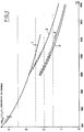
- the glass in order to carry out such an internal centrifugation, it is essential that the glass exhibit adequate rheological behavior. Firstly, the glass must be able to be presented in a state such that it is stretchable, the diameter of the orifices of the centrifuge being of the order of a millimeter or at most a few tenths of a millimeter while that of the fibers produced must be on the order of a few microns. The filaments which escape from the centrifuge must therefore be thinned by at least a factor of one hundred. If the temperature of the glass is too high, or in other words if the glass is too fluid, there will be no stretching and it will eventually form, due to the surface tension, the droplets and not the fibers (resolution temperature in drops).
- the formation stage is added the problem of devitrification, the glass not having to be placed in conditions where it crystallizes at a sufficiently high speed taking into account its residence time in the centrifuge, time without common measurement with the contact time between the glass and the rotating member of a fiber drawing by external centrifugation.
- the field of working temperatures is therefore also limited by the liquidus temperature (temperature corresponding to a zero speed of crystallization for a glass in thermal equilibrium), or rather in accordance with the use of this art by the upper devitrification temperature (temperature corresponding to the complete dissolution of the crystals in 30 minutes, measured from a previously devitrified glass).
- the devitrification temperature is much higher than this temperature corresponding to the highest viscosity so that the working range is limited by the devitrification temperatures and resolution in drops. And in addition, the difference between these two temperatures is often much less than a hundred degrees or even 50 ° C while a soft glass has a working range of more than 200-250 ° C.
- the glass is melted at a temperature higher than the working temperatures, with an even greater difference the harder the glass, which goes in the direction of a greater complication of the problem, it must therefore be cool during the operations which take it from the oven to the peripheral wall of the centrifuge. Because of this, it is practically impossible to operate with a glass very exactly at a given temperature, during all its residence time in the centrifuge, it has so far not been possible to replace for this type of glass with an internal centrifugation technique the external centrifugation technique, the drawbacks of which have been indicated above have been known for a long time.
- these glasses are particularly corrosive and it is therefore necessary to find a material for the manufacture of the centrifuge which resists chemical attack all the more rapid as the temperature and the flow rates are particularly high; in addition the size of the centrifuges, generally between 200 and 1000 mm in diameter, the large number of outlet orifices and the shape studied in order to withstand the intense mechanical forces due to rotation and creep during long durations of use do not allow to consider the realization of centrifuge in refractory alloys for example platinum.
- the present invention aims at improving the techniques for producing mineral fibers by the internal centrifugation process with a view to widening the range of glasses capable of being drawn in this way under satisfactory industrial conditions.
- the object of the invention is also a new centrifuge for implementing the method according to the invention.
- the method according to the invention consists in pouring the material in the molten state inside a centrifuge whose peripheral band is pierced with a very large number of outlet orifices, the wall internal of the peripheral band being at a temperature significantly higher than the external wall.
- the method according to the invention thus proceeds with a large temperature gradient from the inside to the outside.
- the temperature difference will advantageously be chosen between 50 and 300 ° C and preferably between 100 and 200 ° C, this for a wall thickness of a few millimeters, and generally around 5mm.
- This temperature gradient is advantageously such that the internal temperature is much higher than the temperature at which the material to be fiberized begins to devitrify while the external temperature is low enough for the viscosity of the glass to be high enough at the time of drawing.
- the drawing of the filaments is carried out just at the periphery of the centrifuge, therefore at a time when the adequate viscosity is obtained. So we can stretch any kind of glass even if their field of work is almost nonexistent, and this without fear that a plug will form inside the centrifuge by a solidification of the glass which devitrifies and it matters little that the viscosity of the glass suddenly increases just after the emergence of the filament.
- An advantage of the process according to the invention is also probably linked to the fact that in most of its path through the orifices, the glass is still very fluid and therefore has a high flow rate and is kept high for all this time. path. Therefore, not only is there any danger of devitrification inside the centrifuge, but in addition, the residence times of the glass in the orifices are anyway very short, which again is favorable from the point of view of devitrification.
- the invention makes it possible, for example, to work with natural rocks, in particular basalts which do not require the addition of fluxes and therefore a cost price lower than that of a soda glass and which moreover are advantageously refractory and lead to the production of a wool whose resistance to high temperature is improved which can be used for insulation at high temperature or as fire-resistant products.
- the stretching can be purely centrifugal and in this case the centrifuge is surrounded by a gaseous current flowing at low speed, serving for the thermal conditioning of the external peripheral band and of the filaments to which are possibly added at greater distance. currents produced by an annular ring and intended to break the fibers and entrain them towards the hood fiberizing. It is also possible to operate with a gaseous drawing, added to the centrifugal force, due to the action of a gaseous current flowing at very high speed, this gaseous current then playing, in addition to its role of thermal conditioning, that of drawing by fluid.
- the authors of the present invention have also developed a centrifuge for the implementation of the invention, that is to say a centrifuge capable of working with a temperature gradient depending on the thickness of the wall of the peripheral strip.
- This first objective is satisfied with a centrifuge whose peripheral band is made of a material such that the thermal conductivity, measured parallel to a radius of the centrifuge is at least less than 20 Wm ⁇ 1C ⁇ 1, at 1000 ° C and preferably less at 10 Wm ⁇ 1C ⁇ 1 and whose thermal diffusivity always measured parallel to a radius and at 1000 ° C is preferably less than 5 10 ⁇ 6 M2s ⁇ 1, this material must also be able to withstand an interior temperature particularly high compatible with the melting temperatures of glasses such as for example natural basalts. These temperatures being above 1000 ° C., that is to say at the current limit of use of refractory steels, the authors of the present invention have turned to ceramic materials.
- the ceramic is not corroded due to oxidation by the molten material whatever it is and therefore especially even if it is a particularly corrosive material of the basalt glass type and / or blast furnace slag.
- the the mechanical resistance of the part should also be as high as possible, even if it is well known that ceramics generally have a tenacity approximately ten times lower than the tenacity of metals.
- the resistance to thermal shock must be high, in other words the coefficient of expansion of the part must be as low as possible.
- silicon nitrides can also be used.
- the part is obtained for example by sintering.
- non-porous ceramics are used, the apparent density of which is as close as possible to their theoretical maximum density, which leads to parts which are less easily corroded.
- Such a ceramic resists oxidation by oxygen in the air very well. This good behavior is explained by the formation of a protective layer of silica on the surface of the ceramic part due to surface oxidation.
- molten glasses it is more particularly advantageous to work with a molten material whose composition is relatively acid, that is to say with a content of acid elements such as alumina, boron, silica, phosphorus relatively high , so as to limit corrosion phenomena.
- Ceramic materials studied are that of ceramic matrix composites and fibrous reinforcements which have a significantly increased toughness compared to that of monolithic ceramics.
- the choice is more particularly focused on SiC-SiC or SiC-C ceramics, comprising a matrix of silicon carbide reinforced by fibers themselves of silicon carbide (SiC-SiC) or carbon (SiC-C).
- SiC-SiC silicon carbide reinforced by fibers themselves of silicon carbide
- SiC-C-C silicon carbide
- SiC-C-C carbon
- the part is produced by impregnation by cracking of a gaseous precursor ceramized during deposition in a preform obtained by stacking in contact with layers of fabric made of fibers of silicon carbide or carbon. Technologies similar to those developed for polymer composites allow the industrial manufacture of such parts, including according to relatively large diameters and for example greater than 600 mm.
- the ceramic material used having a very low tendency to creep compared to that of metallic materials at the temperatures used here, the shape of the centrifuge can be somewhat simplified and more rounded because even with a high rotational speed it generally remains at stress levels not exceeding the elastic limit of the material.
- the reinforcing fibers make it possible to generate an energy absorbing mechanism which limits the propagation of micro-cracks and allows a certain elastic deformation.
- Such a ceramic can operate under non-oxidizing conditions at a temperature above 1200 ° C for SiC-SiC, and at 1400 ° C for SiC-C.
- the holes through which the glass escapes can be obtained by laser drilling.
- the material is particularly remarkable for its toughness of the order of 30 MPa ⁇ m which gives it good resistance to thermal shock.
- the silicon carbide oxidizes and, as in the case of silicon nitride, a passive protective layer of silica is formed.
- SiC-SiC ceramics Another remarkable characteristic of SiC-SiC ceramics is their much lower thermal conductivity than that of refractory steels, to which is added a very low diffusivity coefficient which accompanies a fairly low thermal inertia due to a density which is only order of 2.5.
- a thermal conductivity of the order of 4 to 5 Wm ⁇ 1C ⁇ 1 while for the same temperature of 1000 ° C this thermal conductivity is of the order of 22 Wm ⁇ 1C ⁇ 1 for a refractory steel used for traditional centrifuges, refractory steels which are however very poor thermal conductors compared to ordinary steels.
- this low density means that the centrifuges thus produced are remarkably light, hence less efforts to be made at the level of the motor shaft and the mounting members.
- a SiC-SiC ceramic is particularly suitable for implementing the method according to the invention insofar as it is not really inclined to homogenize its temperature, even after a relatively long time. It is therefore possible to operate with a temperature gradient which changes little and which can therefore be maintained without having to overheat the internal part of the centrifuge.
- a more negative aspect of this particular thermal behavior is that it is particularly difficult to preheat the centrifuge when starting the fiberizing process; it has been found, however, that isothermal heating over the entire height of the peripheral strip, but not according to the thickness, can be obtained by means of an annular burner preferably with several divergent jets directed towards the internal wall of the strip peripheral and external burners possibly supplemented by one or more oxyacetylene torches, the heating having to be controlled continuously for example by means of an optical pyrometer so as to avoid any overheating. Preheating by internal burner makes it possible to reduce the number of zones being in traction, more particularly at the level of all the drilling orifices.
- Ceramics with a silicon carbide matrix reinforced with carbon fibers are also very particularly advantageous, their performance from the point of view of their resistance to high temperature, their tenacity, their thermal conductivity and their use being very comparable, even slightly superior to those of ceramics reinforced with silicon carbide fibers.
- These ceramics reinforced with carbon fibers are also good electrical conductors which optionally allows heating by electromagnetic induction.
- a last point studied is that of the connection between the ceramic part and the essential metal parts of the centrifuge which must in one way or another be connected to its motor shaft.
- This connection can for example be ensured by blocking the flat edge of the ceramic part between two metal flanges fixed to one another, metal against metal, and by interposing, between the ceramic part and the metal flanges, flexible joints for example in the form of felt in alumina fibers or other refractory fibers or in the form of exfoliated graphite papers.
- This flexible fixing allows relative sliding between the metal parts which expand enormously and the ceramic part which it hardly expands.
- connection device is completed by a centering device which can advantageously consist of a set of 3 ceramic studs carried by one of the metal flanges, studs which are positioned in oblong radial housings formed on the edge of the part. ceramic and regularly spaced at 120 °.
- the second type of product is rock wool, so called because it is often produced from natural rocks of the basalt type, although other compositions, in particular products derived from the steel industry such as slag from blast furnaces, are also used.
- silica content As a corollary to this still relatively low silica content, it is possible to employ a low content of alkalis, that is to say of fluxes. Furthermore, the content of oxidants such as ferric or even ferrous oxides and sulfur must be as low as possible so as to have a glass as reducing and acidic as possible, therefore having on the one hand a low tendency to dissolve silica due to its weak basic character and on the other hand not promoting oxidation to silicon carbide which is certainly useful when it comes to forming a protective layer on the surface but which is all the same the result of a attack of the centrifuge which must not progress towards the core thereof.
- oxidants such as ferric or even ferrous oxides and sulfur
- this limit is really only one with regard to the residence of the glass in the centrifuge because the speed of drawing - and of cooling which then takes place on the fiber - is such that it is perfectly possible to stretch without devitrification can occur.
- the fiberizing takes place on a glass being cooled while the upper devitrification temperature is measured from a devitrified glass. There is therefore no perfect coincidence of the limit temperatures but, however, the closer the working temperature is to the upper devitrification temperature, the greater the risk of being unable to operate. In any case, it is imperative that the appropriate viscosity is obtained at the time of fiberizing and that the glass is not at a temperature below the upper devitrification temperature inside the centrifuge.
- Meilleraie basalt is the preferred according to the invention, because in addition to its more favorable rheological behavior, it is less aggressive for ceramic centrifuges.
- the method according to the invention allows the fiberizing of a very large number of glasses whose rheological behavior is particularly critical due to the narrowness of their field of work, that is to say that this is limited by problems of devitrification as in the case of basaltic glasses, either because it is only due to viscosity problems when the latter decreases very greatly with temperature.
- narrow for example means a deviation of less than 100 ° C or even 50 ° C.
- the authors have been led to develop a new type of centrifuge capable of operating with a gradient of temperature can for example reach 200 ° C between the inner and outer walls, although it should be understood that the centrifuge according to the present invention is not limited to the case of the implementation of the aforementioned fiberizing process and that can also be used in more isothermal conditions, with less refractory glass compositions, and nevertheless provide a series of advantages which will be listed below.
- the first type of material selected is silicon nitride, for example of the RBSN type (Reaction Bonded Silicum Nitride, obtained by sintering-reaction under nitrogen of a silicon powder) of the Si3N4 type, or of the SIALON type, sintered material having good thermal properties up to temperatures in the region of 1300 ° C. and which is advantageously relatively easy to machine. Its mechanical resistance at 1000 ° C is 450 MPa and its coefficient of linear expansion between 20 and 1000 ° C is 3 10 ⁇ 6 C ⁇ 1. The thermal conductivity of this material is 20 Wm ⁇ 1 ° C ⁇ 1 at 1000 ° C which makes it a very good insulator.
- RBSN type Reaction Bonded Silicum Nitride, obtained by sintering-reaction under nitrogen of a silicon powder
- SIALON type sintered material having good thermal properties up to temperatures in the region of 1300 ° C. and which is advantageously relatively easy to machine. Its mechanical resistance at 1000 ° C is 450 MPa and its coefficient
- this material has a density of around 3.2, a very low density associated with low diffusivity.
- the sintering technique allows the production of parts even of fairly complex shapes, the orifices being able to be prepared from the start, raw by materializing them with rods removed once the part is shaped, the diameter of the orifices being possibly rectified with diamond.
- the ceramic material used has a very low porosity, its apparent density preferably being greater than 97% of the maximum theoretical density. This condition which it is quite simple to verify experimentally if it is met constitutes a non-destructive test of the quality of the part and is the sign of an almost total absence of defects authorizing a good resistance to creep and a good resistance to bending .
- silicon nitride Very satisfactory from the point of view of its resistance to thermal shock and its hardness, silicon nitride nevertheless has a relatively low tenacity (of the order of 5.4 MPa ⁇ m) which makes it difficult to produce large centrifuges. diameters, for example of a diameter of 400 mm or more, the centrifuges being by definition driven at high speed, with centrifugal accelerations for example between 4000 and 20,000 m / s2 if one takes place under the advantageous conditions of the point of view of the quality of the fibers proposed by the European patent EP-B1- 91 381.
- composite ceramics are preferably used with a silicon carbide matrix reinforced by silicon carbide fibers or carbon fibers, ceramics with toughness values of 25-30 and 45-52 respectively. MPa ⁇ m, these latter values are very close to those of metals. These composite ceramics therefore practically no longer exhibit the brittle nature normally characteristic of this type of material.
- composites are obtained by the preparation of preforms by forming stacks as compact as possible of fabric layers made of silicon carbide or carbon fibers.
- the network of fibers then undergoes one or preferably a series of impregnation by vapor phase infiltration, at high temperature to obtain a pyrolitic cracking of the precursor; the precursor gas used being typically trichloro-methoxy-silane.
- the blank is optionally machined for finishing and the orifices are formed for example by laser drilling.
- the mechanical performance is as follows: tensile strength 200 MPa at 1000 ° C, this resistance being limited to 150 MPa at 1400 ° C, hence in practice a temperature limit of use between 1200-1300 ° C, Young's modulus 200 GPa at 1000 ° C, 170 GPa at 1400 ° C, compressive strength in the thickness (perpendicular to the fabric layers) 380-250 MPa, in the plane of the fabric layers 480- 300 MPa.
- the composite ceramic parts are not isotropic, their properties being different depending on whether they are measured parallel or perpendicular to the layers of tissue, these being arranged parallel to the peripheral wall of the centrifuge, which is all the more advantageous in within the framework of the implementation of the method according to the invention that it is precisely in the thickness, perpendicular to the layers of fabric, that the thermal conductivity of the material is greatest, the fibrous network not being able to play the role of conductor thermal.
- the greater thermal conductivity in the plane of the fabric layers is rather advantageous since it helps in the non-formation of thermal gradients according to the height of the strip.
- a SiC-SiC ceramic has, for a temperature between 1000 and 1400 ° C., a constant thermal diffusivity of 5 10 ⁇ 6 M2 s ⁇ 1 in the plane parallel to the layers of the fabric and in the direction perpendicular to this plane of 2 10 ⁇ 6 M2 s ⁇ 1.
- the phenomenon is even more accentuated with a ceramic reinforced with conductive carbon fibers where the thermal diffusivity between 1000 and 1400 ° C is respectively 7-8 10 ⁇ 6 M2 s ⁇ 1 in the parallel plane and 2 10 ⁇ 6 M2 s ⁇ 1 in the thickness, the thermal conductivity being 17 WmK in the thickness and 33 WmK in the plane.
- This very low diffusivity is accompanied, as with silicon nitride, with a very low density and respectively 2.5 for an SiC-SiC ceramic and 2.1 for an SiC-C ceramic, density which leads to the production of very light which are therefore easier to rotate.
- SiC-C ceramics have better performance than SiC-SiC ceramics.
- the realization of centrifuges in ceramic all silicon carbide is simpler, the SiC fibers exposed during the drilling of the orifices can be brought into contact with the molten glass which is not the case of carbon fibers which would be transformed into carbon dioxide while the fibers of silicon carbide are eroded like the matrix, with however a kinetics of degradation reaction can be a little faster due to the fineness of the fibers, the silicon carbide being transformed into silicon which then constitutes a protective layer.
- a protective treatment of the orifices drilled through the wall for example by ceramization with silicon carbide or other ceramic deposited in a thin layer resistant to corrosion by glasses.
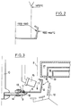
- FIG. 3 A complete assembly of a centrifuge according to the invention has been shown diagrammatically in FIG. 3, in this particular case produced in an SiC-SiC ceramic.
- ceramic centrifuge is simply meant the part of the centrifuge capable of being in contact with the molten glass or directly engaged with the gaseous environment at high temperature. All the other parts are preferably metallic for reasons of cost and feasibility.
- the ceramic part itself is therefore constituted by an O-section 5, sub divided into three parts: the peripheral band proper 6, pierced with for example 20,000 orifices whose diameter is for example between 0.2-0.7 mm and preferably around 0.5 for a centrifuge with a diameter of 400 mm, for a strip height of the order of 50 mm.
- the toroidal section 5 also includes a reverse 7 which gives good mechanical rigidity to the part and a flat portion 8 which receives the stream of molten glass 9 and where possibly a reserve of molten glass is formed.
- This portion 8 which therefore constitutes the bottom of the centrifuge is fixed to a metal hub 9 according to a method of fixing detailed below.
- the proposed scheme is not entirely in accordance with an actual part, the angles of which are preferably more slightly rounded, but already makes it possible to observe that the parts according to the invention are with fairly pure lines, elements of local reinforcements not being here. not necessary due to the practically zero expansion of the ceramic part. In particular, it is not necessary to provide, as in the case of metal centrifuges, an inclined part in the shape of a "tulip", the creep phenomena not being observed, or at least not leading to significant deformations.
- This aspect of the ceramic centrifuges according to the invention is independent of the way in which the fiberizing is carried out and of the glass composition used and explains the advantage of this new type of centrifuge even with a fiberizing and a conventional composition. It is known in fact that the creep of the metal centrifuge causes a modification of the conditions of fiber formation, the filaments being for example emitted at a closer distance from the stretch burner; however, any modification in the conditions of fiber formation is accompanied by a slight modification in the quality of the fibers, for example a variation in their diameter, which is considered by the manufacturer to be negative because its objective is generally perfect consistency of the quality.
- centrifuges according to the invention being able to withstand higher temperatures than metal centrifuges, one can also choose to work with glasses of ordinary composition but slightly warmer therefore smoother, requiring less energy during gaseous drawing and thus increasing the share of centrifugation in drawing.
- At least three oblong housings 11 regularly spaced are provided on the underside of the bottom 8. These oblong housings are occupied by studs 12 also made of ceramic, heat shrunk in the metal hub 9, the shrinking allowing extremely rigorous positioning. These pads move radially when the hub 9 expands and thus ensure proper centering of the centrifuge.
- the bottom 8 is trapped by a circular metal flange 13, fixed to the hub 9 for example by bolts 14, in a metal against metal fixing.
- the clearance between the bottom 8 and the flange 13 on the one hand, and the hub 9 on the other hand is filled by a refractory joint which maintains the ceramic part by pinching without clamping, the force being thus distributed over a very large surface .
- a felt in alumina fibers or other refractory fibers graphite seals are however preferred, in particular in exfoliated graphite paper which are elastic and can thus reversibly deform the parts, the graphite can be used here because enclosed in a closed volume without renewal of the air.
- the centrifuge is surrounded by burners used for preheating, maintaining the temperature and creating a hot atmosphere and / or gaseous drawing currents along the peripheral wall.
- the internal wall of the peripheral strip is heated by internal burners 15 mounted in a crown, these internal burners preferably being with diverging jets so as to cover the entire height of the wall.
- the outer wall is heated by the lip 16 of an annular burner 17.
- the preheating is carried out by respecting a temperature rise curve taking into account the resistance to thermal shocks of the ceramic, a wall temperature at least greater than 1000 ° C. having for example to be reached before the casting begins if one chooses to fiberizing with a centrifuge temperature between 1200 and 1300 ° C.
- this preheating must be carried out under as isothermal conditions as possible, seen in sections cut according to the thickness (therefore parallel to the layers of fabric in the case of a composite ceramic); the problem posed here is linked to the very low thermal diffusivity of ceramics which practically do not transmit the heat received at one point to neighboring parts.
- the external annular burner 17 should preferably be able to emit gas streams whose temperature corresponds to the desired temperature for the external wall of the peripheral strip and the speed is at least equal to the peripheral speed of the centrifuge, or to use the above example at least equal to 50 ms ⁇ 1, these currents emitted essentially perpendicular to the glass filaments thus contribute to their drawing and entrain them towards the fiber receiving device.
- the fiberizing device is further completed by a blowing ring 18 emitting through an opening 19 of the jets relatively more veloces, at a temperature lower than the temperature required for a gaseous stretching and which, in a manner well known in this art, breaks the filaments into fibers and impels their fall towards reception.
- the centrifuge according to the invention can operate with a temperature gradient depending on the thickness (therefore perpendicular to the layers of fabric) which can reach, for example, 200 ° C., such a difference making it possible to establish without difficulty the recommended temperature profile.
- this temperature profile thus made it possible to fiberize in good conditions the Meilleraie basalt, the composition of which was given above.
- the fibers of larger diameters (30 and 35 microns) were obtained with a pull of 30 kg per day and per orifice, this with a practically zero content of fiber which is particularly remarkable for a basalt glass.
Landscapes
- Engineering & Computer Science (AREA)
- Chemical & Material Sciences (AREA)
- Life Sciences & Earth Sciences (AREA)
- General Life Sciences & Earth Sciences (AREA)
- Geochemistry & Mineralogy (AREA)
- Manufacturing & Machinery (AREA)
- Materials Engineering (AREA)
- Organic Chemistry (AREA)
- Glass Compositions (AREA)
- Manufacture, Treatment Of Glass Fibers (AREA)
- Yarns And Mechanical Finishing Of Yarns Or Ropes (AREA)
- Inorganic Fibers (AREA)
- Spinning Methods And Devices For Manufacturing Artificial Fibers (AREA)
- Preliminary Treatment Of Fibers (AREA)
- Paper (AREA)
- Manufacture Of Alloys Or Alloy Compounds (AREA)
- Seasonings (AREA)
- Reinforced Plastic Materials (AREA)
- Adornments (AREA)
- Surface Treatment Of Glass Fibres Or Filaments (AREA)
Applications Claiming Priority (2)
| Application Number | Priority Date | Filing Date | Title |
|---|---|---|---|
| FR9013354 | 1990-10-29 | ||
| FR9013354A FR2668470B1 (fr) | 1990-10-29 | 1990-10-29 | Procede et dispositif de production de fibres par centrifugation interne et application au fibrage de certains verres. |
Publications (2)
| Publication Number | Publication Date |
|---|---|
| EP0484211A1 true EP0484211A1 (de) | 1992-05-06 |
| EP0484211B1 EP0484211B1 (de) | 1995-07-26 |
Family
ID=9401639
Family Applications (1)
| Application Number | Title | Priority Date | Filing Date |
|---|---|---|---|
| EP91402850A Revoked EP0484211B1 (de) | 1990-10-29 | 1991-10-25 | Verfahren und Vorrichtung zum Herstellen von Glasfasern mittels Zentrifugieren un Anwendung von bestimmtem Glas zum Zerfasern |
Country Status (26)
| Country | Link |
|---|---|
| US (1) | US5176729A (de) |
| EP (1) | EP0484211B1 (de) |
| JP (1) | JPH04265247A (de) |
| KR (1) | KR920007938A (de) |
| CN (1) | CN1062127A (de) |
| AT (1) | ATE125521T1 (de) |
| AU (1) | AU648831B2 (de) |
| BR (1) | BR9104665A (de) |
| CA (1) | CA2054326A1 (de) |
| CZ (1) | CZ280908B6 (de) |
| DE (1) | DE69111567T2 (de) |
| DK (1) | DK0484211T3 (de) |
| ES (1) | ES2078475T3 (de) |
| FI (1) | FI94749C (de) |
| FR (1) | FR2668470B1 (de) |
| HU (1) | HUT66662A (de) |
| IE (1) | IE70330B1 (de) |
| IS (1) | IS3771A7 (de) |
| MX (1) | MX174325B (de) |
| NO (1) | NO914143L (de) |
| NZ (1) | NZ240336A (de) |
| PL (1) | PL168379B1 (de) |
| RU (1) | RU2053207C1 (de) |
| TR (1) | TR25519A (de) |
| YU (1) | YU48062B (de) |
| ZA (1) | ZA918561B (de) |
Cited By (6)
| Publication number | Priority date | Publication date | Assignee | Title |
|---|---|---|---|---|
| EP0525816A1 (de) * | 1991-08-02 | 1993-02-03 | Isover Saint-Gobain | Verfahren und Vorrichtung zum Herstellen von Mineralfasern und so hergestellte Mineralfasern |
| EP0583792A1 (de) * | 1992-08-20 | 1994-02-23 | Isover Saint-Gobain | Verfahren und Vorrichtung zum Herstellen von Mineralwolle und Mineralwolle daraus hergestellt |
| EP0583791A1 (de) * | 1992-08-20 | 1994-02-23 | Isover Saint-Gobain | Verfahren zum Herstellen von Mineralwolle und Mineralwolle mittels dieses Verfahren hergestellt |
| EP1182177A1 (de) | 2000-08-24 | 2002-02-27 | Deutsche Rockwool Mineralwoll GmbH & Co. OHG | Dämmstoffelement sowie Verfahren und Vorrichtung zur Herstellung eines Dämmstoffelements, insbesondere einer roll- und/oder wickelbaren Dämmstoffbahn aus Mineralfasern |
| WO2016022762A1 (en) * | 2014-08-07 | 2016-02-11 | Knauf Insulation, Inc. | Multi-component rotary spinner apparatuses, systems and methods for producing fiber from molten material |
| WO2018111198A1 (en) | 2016-12-12 | 2018-06-21 | Izoteh D.O.O. | Coated rotating wheel for mineral melt fiberization and method for coating of a rotating wheel for mineral melt fiberization |
Families Citing this family (12)
| Publication number | Priority date | Publication date | Assignee | Title |
|---|---|---|---|---|
| DE19730996A1 (de) * | 1997-07-18 | 1999-01-21 | Klaus Rennebeck | Verfahren zur Herstellung von keramischen Fasern, die danach hergestellten keramischen Fasern und deren Verwendung |
| FR2783516B1 (fr) * | 1998-09-17 | 2000-11-10 | Saint Gobain Isover | Composition de laine minerale |
| FR2809387B1 (fr) * | 2000-05-23 | 2002-12-20 | Saint Gobain Isover | Procede de fabrication de laine minerale, alliages a base de cobalt pour le procede et autres utilisations |
| FR2811661B1 (fr) * | 2000-07-13 | 2003-05-02 | Saint Gobain Isover | Produit d'isolation thermique/phonique a base de laine minerale et son procede de fabrication |
| EP1495859B1 (de) * | 2003-07-08 | 2008-09-03 | Airbus Deutschland GmbH | Leichtbaustruktur |
| ITMI20031877A1 (it) * | 2003-09-30 | 2005-04-01 | Saint Gobain Isover Italia S P A | Pannello isolante a base di fibre minerali e relativo metodo di produzione. |
| BRPI0415028A (pt) * | 2003-10-06 | 2006-12-12 | Saint Gobain Isover | canal de ventilação e/ou ar condicionado e respectivo revestimento interno/externo |
| US20070000286A1 (en) * | 2005-07-01 | 2007-01-04 | Gavin Patrick M | Fiberizing spinner for the manufacture of low diameter, high quality fibers |
| US7635521B2 (en) * | 2006-02-10 | 2009-12-22 | Corning Incorporated | Glass compositions for protecting glass and methods of making and using thereof |
| US8104311B2 (en) * | 2006-05-09 | 2012-01-31 | Johns Manville | Rotary fiberization process for making glass fibers, an insulation mat, and pipe insulation |
| US20120144869A1 (en) * | 2010-12-10 | 2012-06-14 | Schott Corporation | Glass optical waveguides incorporating materials of interest and methods of fabricating the same |
| AU2022387695A1 (en) * | 2021-11-15 | 2024-05-23 | Blasch Precision Ceramics, Inc. | Ceramic article with holes and method of making the same |
Citations (3)
| Publication number | Priority date | Publication date | Assignee | Title |
|---|---|---|---|---|
| FR2012546A1 (de) * | 1968-07-09 | 1970-03-20 | Owens Corning Fiberglass Corp | |
| US4185980A (en) * | 1978-09-15 | 1980-01-29 | Owens-Corning Fiberglas Corporation | Manufacturing glass with improved silicon carbide bushing operation |
| FR2536385A1 (fr) * | 1982-11-22 | 1984-05-25 | Spafi | Centrifugeur poreux pour le fibrage de matieres thermoplastiques, notamment de verre |
Family Cites Families (11)
| Publication number | Priority date | Publication date | Assignee | Title |
|---|---|---|---|---|
| US2624912A (en) * | 1946-05-31 | 1953-01-13 | Saint Gobain | Process and apparatus for the production of fibers from thermoplastics |
| US3227536A (en) * | 1962-01-18 | 1966-01-04 | Miles S Firnhaber | Apparatus for manufacturing fibers of thermoplastic material |
| US3928009A (en) * | 1972-03-02 | 1975-12-23 | Walter Merton Perry | Rotary forming unit for fine mineral fibers |
| US3785791A (en) * | 1972-03-02 | 1974-01-15 | W Perry | Forming unit for fine mineral fibers |
| US4058386A (en) * | 1972-12-22 | 1977-11-15 | Johns-Manville Corporation | Method and apparatus for eliminating external hot gas attenuation in the rotary fiberization of glass |
| DE2911510A1 (de) * | 1978-12-08 | 1980-06-19 | Saint Gobain | Verfahren, vorrichtung und glaeser zum herstellen von glasfasern und damit hergestellte glasfasern |
| US4756732A (en) * | 1982-04-06 | 1988-07-12 | Isover Saint-Gobain | Glass fiberization method |
| US4534779A (en) * | 1982-12-22 | 1985-08-13 | Owens-Corning Fiberglas Corporation | Method and apparatus for heating a mineral fiber forming spinner |
| US4627868A (en) * | 1985-08-19 | 1986-12-09 | Owens-Corning Fiberglas Corporation | Method and apparatus for producing mineral fibers |
| US4689061A (en) * | 1986-05-20 | 1987-08-25 | Owens-Corning Fiberglas Corporation | Method and apparatus for producing fine fibers |
| US5015278A (en) * | 1990-03-12 | 1991-05-14 | Owens-Corning Fiberglas Corporation | Open bottomed spinner for mineral fibers |
-
1990
- 1990-10-29 FR FR9013354A patent/FR2668470B1/fr not_active Expired - Lifetime
-
1991
- 1991-10-17 IS IS3771A patent/IS3771A7/is unknown
- 1991-10-22 NO NO91914143A patent/NO914143L/no unknown
- 1991-10-23 AU AU86058/91A patent/AU648831B2/en not_active Ceased
- 1991-10-23 YU YU169691A patent/YU48062B/sh unknown
- 1991-10-24 IE IE372191A patent/IE70330B1/en not_active IP Right Cessation
- 1991-10-24 NZ NZ240336A patent/NZ240336A/xx unknown
- 1991-10-25 CZ CS913246A patent/CZ280908B6/cs unknown
- 1991-10-25 EP EP91402850A patent/EP0484211B1/de not_active Revoked
- 1991-10-25 DE DE69111567T patent/DE69111567T2/de not_active Revoked
- 1991-10-25 AT AT91402850T patent/ATE125521T1/de not_active IP Right Cessation
- 1991-10-25 DK DK91402850.1T patent/DK0484211T3/da active
- 1991-10-25 TR TR91/1057A patent/TR25519A/xx unknown
- 1991-10-25 ES ES91402850T patent/ES2078475T3/es not_active Expired - Lifetime
- 1991-10-28 CA CA002054326A patent/CA2054326A1/fr not_active Abandoned
- 1991-10-28 PL PL91292204A patent/PL168379B1/pl unknown
- 1991-10-28 RU SU915001966A patent/RU2053207C1/ru active
- 1991-10-28 ZA ZA918561A patent/ZA918561B/xx unknown
- 1991-10-28 HU HU913382A patent/HUT66662A/hu unknown
- 1991-10-28 FI FI915072A patent/FI94749C/fi not_active IP Right Cessation
- 1991-10-28 CN CN91111133A patent/CN1062127A/zh active Pending
- 1991-10-28 BR BR919104665A patent/BR9104665A/pt not_active Application Discontinuation
- 1991-10-29 JP JP3283348A patent/JPH04265247A/ja active Pending
- 1991-10-29 KR KR1019910019030A patent/KR920007938A/ko not_active Ceased
- 1991-10-29 MX MX9101827A patent/MX174325B/es not_active IP Right Cessation
- 1991-10-29 US US07/783,894 patent/US5176729A/en not_active Expired - Fee Related
Patent Citations (3)
| Publication number | Priority date | Publication date | Assignee | Title |
|---|---|---|---|---|
| FR2012546A1 (de) * | 1968-07-09 | 1970-03-20 | Owens Corning Fiberglass Corp | |
| US4185980A (en) * | 1978-09-15 | 1980-01-29 | Owens-Corning Fiberglas Corporation | Manufacturing glass with improved silicon carbide bushing operation |
| FR2536385A1 (fr) * | 1982-11-22 | 1984-05-25 | Spafi | Centrifugeur poreux pour le fibrage de matieres thermoplastiques, notamment de verre |
Cited By (16)
| Publication number | Priority date | Publication date | Assignee | Title |
|---|---|---|---|---|
| TR27648A (tr) * | 1991-08-02 | 1995-06-14 | Saint Gobain Isover | Mineral yününün üretilmesine mahsus usul ve tertibat ile bunun yardimiyla üretilmis mineral yün. |
| WO1993002977A1 (en) * | 1991-08-02 | 1993-02-18 | Isover Saint-Gobain | Method and apparatus for manufacturing mineral wood, and mineral wool produced thereby |
| US6158249A (en) * | 1991-08-02 | 2000-12-12 | Isover Saint-Gobain | Apparatus for manufacturing mineral wool |
| EP0525816A1 (de) * | 1991-08-02 | 1993-02-03 | Isover Saint-Gobain | Verfahren und Vorrichtung zum Herstellen von Mineralfasern und so hergestellte Mineralfasern |
| AU668878B2 (en) * | 1992-08-20 | 1996-05-23 | Isover Saint-Gobain | Method for producing mineral wool, and mineral wool produced thereby |
| WO1994004469A1 (en) * | 1992-08-20 | 1994-03-03 | Isover Saint-Gobain | Method and apparatus for the production of mineral wool, and mineral wool thereby produced |
| WO1994004468A1 (en) * | 1992-08-20 | 1994-03-03 | Isover Saint-Gobain | Method for producing mineral wool, and mineral wool produced thereby |
| TR28303A (tr) * | 1992-08-20 | 1996-04-09 | Saint Gobain Isover | Maden pamugu üretme yöntemi ve cihazi ve bu sekilde üretilen maden pamugu. |
| EP0583791A1 (de) * | 1992-08-20 | 1994-02-23 | Isover Saint-Gobain | Verfahren zum Herstellen von Mineralwolle und Mineralwolle mittels dieses Verfahren hergestellt |
| EP0583792A1 (de) * | 1992-08-20 | 1994-02-23 | Isover Saint-Gobain | Verfahren und Vorrichtung zum Herstellen von Mineralwolle und Mineralwolle daraus hergestellt |
| EP1182177A1 (de) | 2000-08-24 | 2002-02-27 | Deutsche Rockwool Mineralwoll GmbH & Co. OHG | Dämmstoffelement sowie Verfahren und Vorrichtung zur Herstellung eines Dämmstoffelements, insbesondere einer roll- und/oder wickelbaren Dämmstoffbahn aus Mineralfasern |
| DE10041481A1 (de) * | 2000-08-24 | 2002-03-21 | Rockwool Mineralwolle | Dämmstoffelement sowie Verfahren und Vorrichtung zur Herstellung eines Dämmstoffelementes, insbesondere einer roll- und/oder wickelbaren Dämmstoffbahn aus Mineralfasern |
| DE10041481B4 (de) * | 2000-08-24 | 2006-01-19 | Deutsche Rockwool Mineralwoll Gmbh & Co. Ohg | Dämmstoffelement sowie Verfahren und Vorrichtung zur Herstellung eines Dämmstoffelementes, insbesondere einer roll- und/oder wickelbaren Dämmstoffbahn aus Mineralfasern |
| WO2016022762A1 (en) * | 2014-08-07 | 2016-02-11 | Knauf Insulation, Inc. | Multi-component rotary spinner apparatuses, systems and methods for producing fiber from molten material |
| US9624123B2 (en) | 2014-08-07 | 2017-04-18 | Knauf Insulation, Inc. | Multi-component rotary spinner apparatuses systems and methods for producing fiber from molten material |
| WO2018111198A1 (en) | 2016-12-12 | 2018-06-21 | Izoteh D.O.O. | Coated rotating wheel for mineral melt fiberization and method for coating of a rotating wheel for mineral melt fiberization |
Also Published As
Similar Documents
| Publication | Publication Date | Title |
|---|---|---|
| EP0484211B1 (de) | Verfahren und Vorrichtung zum Herstellen von Glasfasern mittels Zentrifugieren un Anwendung von bestimmtem Glas zum Zerfasern | |
| JP3234224B2 (ja) | ミネラルウールおよびその製造方法並びに装置 | |
| US4363878A (en) | Alkali- and heat-resistant inorganic fiber | |
| EP4330203B1 (de) | Verfahren zur herstellung von glasfasern aus unbehandelten mineralmaterialien | |
| CN1087611A (zh) | 生产矿物棉的方法和以该法生产的矿物棉 | |
| EP2807124B1 (de) | Verfahren zur herstellung von mineralwolle | |
| FR2723583A1 (fr) | Refractaires fondus a haute teneur en zircone | |
| EP1753698A1 (de) | Verfahren und vorrichtung zur läuterung und homogenisierung von glas sowie mit diesem verfahren hergestellte produkte | |
| Stewart et al. | Fracture of SiC fiber/glass-ceramic composites as a function of temperature | |
| Guo et al. | C/C–SiC composite fabricated via PCS–Si slurry reactive melt infiltration | |
| EP0404631B1 (de) | Verbundwerkstoffe mit einer verstärkten Glasmatrix und Verfahren für ihre Herstellung | |
| JP6598961B1 (ja) | 無機繊維質成形体 | |
| FR2924442A1 (fr) | Alliage refracaire, assiette de fibrage et procede de fabrication de laine minerale | |
| CA2210510C (fr) | Materiau composite a matrice vitroceramique renforce par des fibres et procede d'obtention | |
| FR2509716A1 (fr) | Composition de verre convenant a la fabrication de fibres | |
| FR3164457A1 (fr) | Procede de fabrication de fibres de verre a partir de calcin de verre bouteille | |
| FR3160693A1 (fr) | Procede de fabrication de fibres de verre a partir de matieres minerales incluant de l’hydroxyde de sodium anhydre | |
| BE474776A (de) |
Legal Events
| Date | Code | Title | Description |
|---|---|---|---|
| PUAI | Public reference made under article 153(3) epc to a published international application that has entered the european phase |
Free format text: ORIGINAL CODE: 0009012 |
|
| AK | Designated contracting states |
Kind code of ref document: A1 Designated state(s): AT BE CH DE DK ES FR GB IT LI LU NL SE |
|
| 17P | Request for examination filed |
Effective date: 19921009 |
|
| 17Q | First examination report despatched |
Effective date: 19940524 |
|
| GRAA | (expected) grant |
Free format text: ORIGINAL CODE: 0009210 |
|
| AK | Designated contracting states |
Kind code of ref document: B1 Designated state(s): AT BE CH DE DK ES FR GB IT LI LU NL SE |
|
| REF | Corresponds to: |
Ref document number: 125521 Country of ref document: AT Date of ref document: 19950815 Kind code of ref document: T |
|
| REF | Corresponds to: |
Ref document number: 69111567 Country of ref document: DE Date of ref document: 19950831 |
|
| ITF | It: translation for a ep patent filed | ||
| GBT | Gb: translation of ep patent filed (gb section 77(6)(a)/1977) |
Effective date: 19951103 |
|
| REG | Reference to a national code |
Ref country code: ES Ref legal event code: FG2A Ref document number: 2078475 Country of ref document: ES Kind code of ref document: T3 |
|
| REG | Reference to a national code |
Ref country code: DK Ref legal event code: T3 |
|
| PLBQ | Unpublished change to opponent data |
Free format text: ORIGINAL CODE: EPIDOS OPPO |
|
| PLBI | Opposition filed |
Free format text: ORIGINAL CODE: 0009260 |
|
| PLBF | Reply of patent proprietor to notice(s) of opposition |
Free format text: ORIGINAL CODE: EPIDOS OBSO |
|
| 26 | Opposition filed |
Opponent name: ROCKWOOL INTERNATIONAL A/S Effective date: 19960423 |
|
| NLR1 | Nl: opposition has been filed with the epo |
Opponent name: ROCKWOOL INTERNATIONAL A/S |
|
| PGFP | Annual fee paid to national office [announced via postgrant information from national office to epo] |
Ref country code: DK Payment date: 19960903 Year of fee payment: 6 |
|
| PGFP | Annual fee paid to national office [announced via postgrant information from national office to epo] |
Ref country code: AT Payment date: 19960906 Year of fee payment: 6 |
|
| PGFP | Annual fee paid to national office [announced via postgrant information from national office to epo] |
Ref country code: SE Payment date: 19960917 Year of fee payment: 6 |
|
| PLBF | Reply of patent proprietor to notice(s) of opposition |
Free format text: ORIGINAL CODE: EPIDOS OBSO |
|
| PGFP | Annual fee paid to national office [announced via postgrant information from national office to epo] |
Ref country code: ES Payment date: 19961016 Year of fee payment: 6 |
|
| PGFP | Annual fee paid to national office [announced via postgrant information from national office to epo] |
Ref country code: FR Payment date: 19961017 Year of fee payment: 6 |
|
| PGFP | Annual fee paid to national office [announced via postgrant information from national office to epo] |
Ref country code: GB Payment date: 19961018 Year of fee payment: 6 |
|
| PGFP | Annual fee paid to national office [announced via postgrant information from national office to epo] |
Ref country code: NL Payment date: 19961023 Year of fee payment: 6 |
|
| PGFP | Annual fee paid to national office [announced via postgrant information from national office to epo] |
Ref country code: CH Payment date: 19961024 Year of fee payment: 6 |
|
| PGFP | Annual fee paid to national office [announced via postgrant information from national office to epo] |
Ref country code: BE Payment date: 19961028 Year of fee payment: 6 |
|
| PGFP | Annual fee paid to national office [announced via postgrant information from national office to epo] |
Ref country code: DE Payment date: 19961102 Year of fee payment: 6 |
|
| PLBF | Reply of patent proprietor to notice(s) of opposition |
Free format text: ORIGINAL CODE: EPIDOS OBSO |
|
| PGFP | Annual fee paid to national office [announced via postgrant information from national office to epo] |
Ref country code: LU Payment date: 19970306 Year of fee payment: 6 |
|
| PLBF | Reply of patent proprietor to notice(s) of opposition |
Free format text: ORIGINAL CODE: EPIDOS OBSO |
|
| RDAH | Patent revoked |
Free format text: ORIGINAL CODE: EPIDOS REVO |
|
| REG | Reference to a national code |
Ref country code: DK Ref legal event code: EBP |
|
| RDAG | Patent revoked |
Free format text: ORIGINAL CODE: 0009271 |
|
| STAA | Information on the status of an ep patent application or granted ep patent |
Free format text: STATUS: PATENT REVOKED |
|
| REG | Reference to a national code |
Ref country code: CH Ref legal event code: PL |
|
| 27W | Patent revoked |
Effective date: 19970515 |
|
| GBPR | Gb: patent revoked under art. 102 of the ep convention designating the uk as contracting state |
Free format text: 970515 |
|
| NLR2 | Nl: decision of opposition |