EP0484218A1 - Vorrichtung zum Ausführen von Arbeiten in nichteruptiven abgelenkten Bohrlöchern - Google Patents
Vorrichtung zum Ausführen von Arbeiten in nichteruptiven abgelenkten Bohrlöchern Download PDFInfo
- Publication number
- EP0484218A1 EP0484218A1 EP91402874A EP91402874A EP0484218A1 EP 0484218 A1 EP0484218 A1 EP 0484218A1 EP 91402874 A EP91402874 A EP 91402874A EP 91402874 A EP91402874 A EP 91402874A EP 0484218 A1 EP0484218 A1 EP 0484218A1
- Authority
- EP
- European Patent Office
- Prior art keywords
- column
- connector
- production
- cable
- fluid
- Prior art date
- Legal status (The legal status is an assumption and is not a legal conclusion. Google has not performed a legal analysis and makes no representation as to the accuracy of the status listed.)
- Granted
Links
- 238000004519 manufacturing process Methods 0.000 claims abstract description 36
- 239000012530 fluid Substances 0.000 claims abstract description 24
- 238000009434 installation Methods 0.000 claims abstract description 17
- 239000004020 conductor Substances 0.000 claims abstract description 7
- 238000013519 translation Methods 0.000 claims abstract description 4
- 238000005259 measurement Methods 0.000 claims description 15
- 230000004913 activation Effects 0.000 claims description 14
- 230000003111 delayed effect Effects 0.000 claims description 5
- 238000000034 method Methods 0.000 claims description 5
- 230000003213 activating effect Effects 0.000 claims description 3
- 238000011144 upstream manufacturing Methods 0.000 claims description 2
- 238000005086 pumping Methods 0.000 abstract description 20
- 230000000712 assembly Effects 0.000 abstract description 2
- 238000000429 assembly Methods 0.000 abstract description 2
- 238000012550 audit Methods 0.000 abstract 1
- 230000000694 effects Effects 0.000 abstract 1
- 239000003208 petroleum Substances 0.000 abstract 1
- 230000014616 translation Effects 0.000 abstract 1
- 238000003780 insertion Methods 0.000 description 5
- 230000037431 insertion Effects 0.000 description 5
- 239000003380 propellant Substances 0.000 description 3
- 230000015572 biosynthetic process Effects 0.000 description 2
- 241000287127 Passeridae Species 0.000 description 1
- 230000005540 biological transmission Effects 0.000 description 1
- 238000007789 sealing Methods 0.000 description 1
Images


Classifications
-
- E—FIXED CONSTRUCTIONS
- E21—EARTH OR ROCK DRILLING; MINING
- E21B—EARTH OR ROCK DRILLING; OBTAINING OIL, GAS, WATER, SOLUBLE OR MELTABLE MATERIALS OR A SLURRY OF MINERALS FROM WELLS
- E21B34/00—Valve arrangements for boreholes or wells
- E21B34/06—Valve arrangements for boreholes or wells in wells
- E21B34/14—Valve arrangements for boreholes or wells in wells operated by movement of tools, e.g. sleeve valves operated by pistons or wire line tools
-
- E—FIXED CONSTRUCTIONS
- E21—EARTH OR ROCK DRILLING; MINING
- E21B—EARTH OR ROCK DRILLING; OBTAINING OIL, GAS, WATER, SOLUBLE OR MELTABLE MATERIALS OR A SLURRY OF MINERALS FROM WELLS
- E21B23/00—Apparatus for displacing, setting, locking, releasing or removing tools, packers or the like in boreholes or wells
- E21B23/08—Introducing or running tools by fluid pressure, e.g. through-the-flow-line tool systems
-
- E—FIXED CONSTRUCTIONS
- E21—EARTH OR ROCK DRILLING; MINING
- E21B—EARTH OR ROCK DRILLING; OBTAINING OIL, GAS, WATER, SOLUBLE OR MELTABLE MATERIALS OR A SLURRY OF MINERALS FROM WELLS
- E21B23/00—Apparatus for displacing, setting, locking, releasing or removing tools, packers or the like in boreholes or wells
- E21B23/14—Apparatus for displacing, setting, locking, releasing or removing tools, packers or the like in boreholes or wells for displacing a cable or a cable-operated tool, e.g. for logging or perforating operations in deviated wells
-
- E—FIXED CONSTRUCTIONS
- E21—EARTH OR ROCK DRILLING; MINING
- E21B—EARTH OR ROCK DRILLING; OBTAINING OIL, GAS, WATER, SOLUBLE OR MELTABLE MATERIALS OR A SLURRY OF MINERALS FROM WELLS
- E21B43/00—Methods or apparatus for obtaining oil, gas, water, soluble or meltable materials or a slurry of minerals from wells
- E21B43/12—Methods or apparatus for controlling the flow of the obtained fluid to or in wells
- E21B43/121—Lifting well fluids
Definitions
- the present invention relates to an improved device for carrying out interventions in deviated non-eruptive production wells, such as activation of production and measurements on the effluents produced.
- the improved device according to the invention makes it possible, for all well configurations, to electrically supply an activation and measurement system by means of a cable provided with a plug-in connector in a deferred manner by means of a current of fluid, this device being arranged to avoid the possible drawbacks of prior devices.
- the improved device makes it possible to carry out interventions, in deviated non-eruptive production wells, such as activation of production and measurements on the effluents produced. It comprises a production column connected to a surface installation comprising at least one connection with an interposed side window, means for closing the annular space between the well and the column, an intervention assembly comprising means for activating the production of the well and the means for measuring at least part of the effluents produced and at least one connecting cable connecting the activation means and / or the measuring means to said installation for surface, said cable being provided with a pluggable connector in a delayed manner, movable along the tubular column by the action of a stream of fluid.
- the device is characterized in that it comprises means for intermittently drifting outside the intervention area, at least part of the fluid current established for the propulsion of said connector, the latter being adapted during its movement to open or close said exhaust means.
- the bypass means comprise for example at least one valve upstream of the measuring means which communicates the interior of the column and the annular space between it and the well.
- this valve is a sliding valve.
- the device may include retractable retaining means for intermittently securing in translation the bypass means.
- the bypass means comprise for example at least one jacket which can slide inside the column and in the vicinity of the intervention zone between a withdrawal position where it discovers openings made through the side wall of the column, and an advanced position where it closes said openings, this jacket being provided internally with radial extensions, a load part associated with the connector, provided with bosses adapted to come into abutment against said radial extensions and push said shirt towards its advanced position and means for intermittently locking the load part with respect to said jacket.
- the device may also include means for intermittently locking said jacket relative to the wall of the column.
- connection cable is for example a multi-conductor cable comprising power supply lines and lines for transmitting control and measurement signals.
- the device may for example comprise a second cable also provided with a pluggable connector in a deferred manner, which connects the activation means and the surface installation.
- the invention also relates to a method for carrying out interventions in deviated non-eruptive production wells, such as activation of production and measurements on the effluents produced comprising the installation of a production column connected to an installation. surface and provided with at least one connection with an interposed side window, means for closing the annular space between the well and the column, an intervention assembly comprising means for activating the production of the well and means for measuring at least part of the effluents produced and at least one connecting cable connecting the activation means and / or the measuring means to said surface installation, said cable being provided with a connector which is movable along the column by the action of a stream of fluid, the intervention assembly being adapted to be connected in a delayed manner with said plug-in connector.
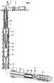
- the well 1 shown in Figs 1, 2 is drilled from a surface installation 2 into an oil formation 3. In its lower part crossing an oil-producing area, the well 3 is deviated by an angle more or less pronounced with respect to the vertical. It is equipped with a tube or "liner" 4 with perforations 5 in its part which crosses the production area. It is a non-eruptive well, the production of which must be activated by a pumping assembly 6 which may include a volumetric pump of the Moineau type for example. According to the embodiment of Fig.1, the pumping assembly 6 is arranged in the vicinity of the end of a production column or tubing 7.
- a measuring assembly 8 can include several different instruments to measure different parameters indicative of production: plotter-ejector, gamma densimeter, capacitance meter etc.
- a sealing member 9 of a known expandable type or with cups, is arranged for example around the column to separate the parts of the well on either side. The effluents from the formation pass through the measuring assembly 8 and through the column 7, they are discharged towards the surface by means of the pumping assembly 6.
- This comprises a drive motor 10 electrically supplied from the surface installation 2 by a multi-conductor cable 11 comprising supply lines and data transmission lines.
- the cable 11 is terminated by a connector 12 which is pluggable in a deferred manner, surmounted by a load bar 13.
- a connector of this type is used for example in the device described in French patent 2,501,777.
- the connector 12 is introduced inside the column by the opening in the wall of a connector 14 of the side-entry sub type, interposed on the drill string which constitutes it.
- By pumping fluid one can move such a connector until it is completely plugged into a multi-contact male plug 15 (Fig 1, 3) fixed on the pumping assembly and connected to the electric motor 10 for driving the pumping assembly 6.
- a multi-contact male plug 15 Fig 1, 3
- the measuring assembly 8 is electrically supplied and can transmit measurement data.
- the device comprises, in the vicinity of the pumping assembly, a bypass valve 17 adapted, in the open position, to divert the fluid used to propel the connector 12 and its load bar 13 towards the annular space 18 around the column 7.
- a bypass valve 17 adapted, in the open position, to divert the fluid used to propel the connector 12 and its load bar 13 towards the annular space 18 around the column 7.
- This valve 17 is a sliding valve for example. It comprises (FIG. 3, 4) a jacket 19 of external section substantially equal to the internal section of the tubular column 7 which can slide from a withdrawal position where it discovers openings 20 in the side wall of the column 7, at its periphery, to an advanced position where it covers these openings. Seals 21 are arranged in the wall of the column on either side of the openings to establish the tightness of the valve 17 in the open position. On its inner wall, the jacket 19 is provided with radial extensions 22 through which the connector 12 can pass freely.
- the load bar 13 is provided with external bosses 23 of greater cross-section than that of the radial extensions 22 so as to come into abutment against it in the valve open position (Fig.
- the device is also arranged so that the withdrawal of the connector disengaging from its insertion position, causes the valve to open.
- the sleeve 19 is provided with an internal groove 24 and the load bar comprises housings for one or more locking elements 25.
- Each element 25 comprises a latch 26 pushed radially by a spring 27 and positioned so as to come to engage in the groove 24 when the load bar is in abutment on the radial extensions 22.
- the tension of the springs 27 is sufficient for the or each lock 26 to drive the jacket when the load bar is pulled back by a traction exerted on the cable 7. This tension of the springs is limited so that the latches disengage from the groove 24 when the traction force exerted on the cable is sufficient, which allows the connector to rise.
- the jacket of the valve is provided externally with grooves 28, 29.
- Housing is provided in the inner wall of the column on either side of the openings 20, for locking elements 30 , 31 analogous for example to element 26.
- each element 29 is blocked in the groove 28.
- each element 31 engages in the groove 29.
- the measuring assembly can be relatively distant from the pumping assembly.
- the connection operations are likewise simplified by connecting the two assemblies by a cable 33 provided with a connector 34 analogous to the connector and by adapting, in the vicinity of the measurement assembly 8, the described device of sliding valve 35 analogous to the valve 19 operated by the translational movements of the load bar 36 associated with the connector 34.
- the previous device can be completed by placing another sliding valve 37 above the pumping assembly so as to also divert the fluid which is used to move the connector towards its engagement position outside the column.
Landscapes
- Geology (AREA)
- Life Sciences & Earth Sciences (AREA)
- Engineering & Computer Science (AREA)
- Mining & Mineral Resources (AREA)
- Environmental & Geological Engineering (AREA)
- Fluid Mechanics (AREA)
- Physics & Mathematics (AREA)
- General Life Sciences & Earth Sciences (AREA)
- Geochemistry & Mineralogy (AREA)
- Quick-Acting Or Multi-Walled Pipe Joints (AREA)
- Infusion, Injection, And Reservoir Apparatuses (AREA)
- Machine Tool Units (AREA)
- Air Bags (AREA)
- Pharmaceuticals Containing Other Organic And Inorganic Compounds (AREA)
Applications Claiming Priority (2)
| Application Number | Priority Date | Filing Date | Title |
|---|---|---|---|
| FR9013692 | 1990-11-02 | ||
| FR9013692A FR2668793B1 (fr) | 1990-11-02 | 1990-11-02 | Dispositif perfectionne d'intervention dans des puits de production devies non eruptifs. |
Publications (2)
| Publication Number | Publication Date |
|---|---|
| EP0484218A1 true EP0484218A1 (de) | 1992-05-06 |
| EP0484218B1 EP0484218B1 (de) | 1995-04-12 |
Family
ID=9401860
Family Applications (1)
| Application Number | Title | Priority Date | Filing Date |
|---|---|---|---|
| EP91402874A Expired - Lifetime EP0484218B1 (de) | 1990-11-02 | 1991-10-25 | Vorrichtung zum Ausführen von Arbeiten in nichteruptiven abgelenkten Bohrlöchern |
Country Status (6)
| Country | Link |
|---|---|
| US (1) | US5217072A (de) |
| EP (1) | EP0484218B1 (de) |
| CA (1) | CA2054782C (de) |
| DK (1) | DK0484218T3 (de) |
| FR (1) | FR2668793B1 (de) |
| NO (1) | NO303143B1 (de) |
Cited By (1)
| Publication number | Priority date | Publication date | Assignee | Title |
|---|---|---|---|---|
| CN101648362B (zh) * | 2009-09-01 | 2010-12-29 | 济南柴油机股份有限公司 | 连杆大头孔光整工艺 |
Families Citing this family (5)
| Publication number | Priority date | Publication date | Assignee | Title |
|---|---|---|---|---|
| FR2677701B1 (fr) * | 1991-06-11 | 1993-09-03 | Inst Francais Du Petrole | Methode pour poursuivre des mesures apres la recuperation d'un outil de mesure immobilise dans un puits. |
| FR2679958B1 (fr) * | 1991-08-02 | 1997-06-27 | Inst Francais Du Petrole | Systeme, support pour effectuer des mesures ou interventions dans un puits fore ou en cours de forage, et leurs utilisations. |
| FR2679957B1 (fr) * | 1991-08-02 | 1998-12-04 | Inst Francais Du Petrole | Methode et dispositif pour effectuer des mesures et/ou interventions dans un puits fore ou en cours de forage. |
| US5361840A (en) * | 1993-04-26 | 1994-11-08 | Bruce Matthews | Well plugging apparatus and method |
| US6913399B2 (en) * | 2003-07-23 | 2005-07-05 | Intel Corporation | Metallized optical fibers and ferrules for optical fibers for direct attachment to photodiodes |
Citations (11)
| Publication number | Priority date | Publication date | Assignee | Title |
|---|---|---|---|---|
| US3552718A (en) * | 1968-03-01 | 1971-01-05 | Otis Eng Co | Sliding sleeve valve and operator therefor |
| US3554281A (en) * | 1969-08-18 | 1971-01-12 | Pan American Petroleum Corp | Retrievable circulating valve insertable in a string of well tubing |
| US3583481A (en) * | 1969-09-05 | 1971-06-08 | Pan American Petroleum Corp | Down hole sidewall tubing valve |
| FR2501777A1 (fr) * | 1981-03-13 | 1982-09-17 | Inst Francais Du Petrole | Methode et dispositif pour effectuer, a l'aide d'outils specialises, des operations telles que des mesures, dans des portions de puits fortement inclinees sur la verticale, ou horizontales |
| US4406335A (en) * | 1980-10-30 | 1983-09-27 | Nick Koot | Special circulation sub |
| EP0307266A1 (de) * | 1987-08-19 | 1989-03-15 | Institut Français du Pétrole | Verfahren und Vorrichtung zur Betätigung von Spezialausrüstungen für Eingriffe in einem Gebohrten Schacht mit mindestens einem stark geneigten Abschnitt in Bezug auf die Vertikale |
| EP0326492A1 (de) * | 1988-01-29 | 1989-08-02 | Institut Français du Pétrole | Vorrichtung und Verfahren zur Durchführung von Arbeitsgängen und/oder Eingriffen in einem Bohrloch |
| US4877089A (en) * | 1987-06-18 | 1989-10-31 | Western Atlas International, Inc. | Method and apparatus for coupling wireline tools to coil tubing |
| FR2637939A1 (fr) * | 1988-10-14 | 1990-04-20 | Inst Francais Du Petrole | Procede et dispositif de diagraphie en puits de production non eruptif |
| EP0389362A1 (de) * | 1989-03-22 | 1990-09-26 | Institut Français du Pétrole | Verfahren und Vorrichtung zur Produktionsmessung in einem eruptiven Bohrloch |
| EP0391809A1 (de) * | 1989-04-06 | 1990-10-10 | Institut Français du Pétrole | Verfahren und Vorrichtung für seismisches Prospektieren in Bohrlöchern, besonders in abgelenkten Bohrlöchern |
Family Cites Families (2)
| Publication number | Priority date | Publication date | Assignee | Title |
|---|---|---|---|---|
| US4159643A (en) * | 1978-07-31 | 1979-07-03 | Camco, Incorporated | Method of and apparatus for measuring bottom hole well pressure |
| FR2575515B1 (fr) * | 1984-12-28 | 1988-11-10 | Inst Francais Du Petrole | Dispositif propulse par pression hydraulique permettant des mesures et des interventions en cours d'injection ou de production dans un puits devie |
-
1990
- 1990-11-02 FR FR9013692A patent/FR2668793B1/fr not_active Expired - Fee Related
-
1991
- 1991-10-25 EP EP91402874A patent/EP0484218B1/de not_active Expired - Lifetime
- 1991-10-25 DK DK91402874.1T patent/DK0484218T3/da active
- 1991-10-31 NO NO914281A patent/NO303143B1/no not_active IP Right Cessation
- 1991-11-01 CA CA002054782A patent/CA2054782C/fr not_active Expired - Fee Related
- 1991-11-04 US US07/787,657 patent/US5217072A/en not_active Expired - Fee Related
Patent Citations (11)
| Publication number | Priority date | Publication date | Assignee | Title |
|---|---|---|---|---|
| US3552718A (en) * | 1968-03-01 | 1971-01-05 | Otis Eng Co | Sliding sleeve valve and operator therefor |
| US3554281A (en) * | 1969-08-18 | 1971-01-12 | Pan American Petroleum Corp | Retrievable circulating valve insertable in a string of well tubing |
| US3583481A (en) * | 1969-09-05 | 1971-06-08 | Pan American Petroleum Corp | Down hole sidewall tubing valve |
| US4406335A (en) * | 1980-10-30 | 1983-09-27 | Nick Koot | Special circulation sub |
| FR2501777A1 (fr) * | 1981-03-13 | 1982-09-17 | Inst Francais Du Petrole | Methode et dispositif pour effectuer, a l'aide d'outils specialises, des operations telles que des mesures, dans des portions de puits fortement inclinees sur la verticale, ou horizontales |
| US4877089A (en) * | 1987-06-18 | 1989-10-31 | Western Atlas International, Inc. | Method and apparatus for coupling wireline tools to coil tubing |
| EP0307266A1 (de) * | 1987-08-19 | 1989-03-15 | Institut Français du Pétrole | Verfahren und Vorrichtung zur Betätigung von Spezialausrüstungen für Eingriffe in einem Gebohrten Schacht mit mindestens einem stark geneigten Abschnitt in Bezug auf die Vertikale |
| EP0326492A1 (de) * | 1988-01-29 | 1989-08-02 | Institut Français du Pétrole | Vorrichtung und Verfahren zur Durchführung von Arbeitsgängen und/oder Eingriffen in einem Bohrloch |
| FR2637939A1 (fr) * | 1988-10-14 | 1990-04-20 | Inst Francais Du Petrole | Procede et dispositif de diagraphie en puits de production non eruptif |
| EP0389362A1 (de) * | 1989-03-22 | 1990-09-26 | Institut Français du Pétrole | Verfahren und Vorrichtung zur Produktionsmessung in einem eruptiven Bohrloch |
| EP0391809A1 (de) * | 1989-04-06 | 1990-10-10 | Institut Français du Pétrole | Verfahren und Vorrichtung für seismisches Prospektieren in Bohrlöchern, besonders in abgelenkten Bohrlöchern |
Cited By (1)
| Publication number | Priority date | Publication date | Assignee | Title |
|---|---|---|---|---|
| CN101648362B (zh) * | 2009-09-01 | 2010-12-29 | 济南柴油机股份有限公司 | 连杆大头孔光整工艺 |
Also Published As
| Publication number | Publication date |
|---|---|
| CA2054782C (fr) | 2002-10-29 |
| CA2054782A1 (fr) | 1992-05-03 |
| NO914281L (no) | 1992-05-04 |
| NO303143B1 (no) | 1998-06-02 |
| FR2668793A1 (fr) | 1992-05-07 |
| DK0484218T3 (da) | 1995-07-03 |
| FR2668793B1 (fr) | 1995-12-15 |
| US5217072A (en) | 1993-06-08 |
| NO914281D0 (no) | 1991-10-31 |
| EP0484218B1 (de) | 1995-04-12 |
Similar Documents
| Publication | Publication Date | Title |
|---|---|---|
| EP0187599B1 (de) | Druckmittelangetriebene Vorrichtung zum Messen und Ausführen von Arbeiten in einem abgelenkten Bohrloch während der Injektion oder der Förderung | |
| EP0122839B1 (de) | Verfahren und Vorrichtung zum Messen und/oder Ausführen von Arbeiten in einem Bohrloch | |
| EP0206917B1 (de) | Vorrichtung und Verfahren zum zeitweiligen Schützen eines am Ende eines Rohrstranges befestigten Werkzeuges zum Messen oder Ausführen von Arbeiten | |
| EP0404669B1 (de) | Verfahren und Vorrichtung zur Durchführung von Perforationsgängen in einem Bohrloch | |
| FR2679958A1 (fr) | Systeme, support pour effectuer des mesures ou interventions dans un puits fore ou en cours de forage, et leurs utilisations. | |
| EP0202151B1 (de) | Vorrichtung für Bohrgestänge oder dergleichen, bestehend aus einem Rohrstück mit einer seitlichen Öffnung für ein Kabel | |
| FR2679957A1 (fr) | Methode et dispositif pour effectuer des mesures et/ou interventions dans un puits fore ou en cours de forage. | |
| EP0132423A1 (de) | Verfahren und Vorrichtung zum Messen und Ausführen von Arbeiten in einem Bohrloch | |
| EP0307266B1 (de) | Verfahren und Vorrichtung zur Betätigung von Spezialausrüstungen für Eingriffe in einem Gebohrten Schacht mit mindestens einem stark geneigten Abschnitt in Bezug auf die Vertikale | |
| FR2787505A1 (fr) | Colonne montante a alesage unique | |
| EP2122118B1 (de) | Messvorrichtung in einem horizontalen bohrloch | |
| EP0457879B1 (de) | Vorrichtung und verfahren zur reinigung eines unterirdischen bohrloches | |
| EP0295291B1 (de) | System zum verschieben eines instrumentenbehälters, sowie messverfahren und/oder eingriffsverfahren in einem bohrloch | |
| EP0484218B1 (de) | Vorrichtung zum Ausführen von Arbeiten in nichteruptiven abgelenkten Bohrlöchern | |
| EP0296207B1 (de) | Verfahren und vorrichtung zum ausführen von messungen und/oder eingriffen in einem unter hydraulischem druck stehenden bohrloch | |
| EP0192558A1 (de) | Vorrichtung zum Einordnen eines Werkzeugs oder Instruments in einem Rohr, insbesondere eine selbständige hydraulische Pumpe, die durch ein Steigrohr gewinnt | |
| CA2045434C (fr) | Methode et dispositif perfectionnes pour conduire des operations de mesure ou des interventions dans un puits | |
| WO2008087281A2 (fr) | Systeme et methode de mesure dans un puits horizontal | |
| CA1279259C (fr) | Dispositif de connexion porteur de charges et de transmission de fluides hydrauliques | |
| OA10433A (fr) | Suspension de la colonne de production d'un puits pétrolier | |
| FR2626647A1 (fr) | Vanne a chemise coulissante pour la production de puits fores dans le sol | |
| FR2609103A1 (fr) | Methode et dispositif pour effectuer des mesures ou/et interventions dans une zone d'un puits et controler la circulation de fluide vers une autre zone de ce puits ou l'on effectue une compression hydraulique | |
| FR2609102A1 (fr) | Methode et dispositif pour effectuer des mesures ou/et interventions dans une zone d'un puits soumise a une compression hydraulique |
Legal Events
| Date | Code | Title | Description |
|---|---|---|---|
| PUAI | Public reference made under article 153(3) epc to a published international application that has entered the european phase |
Free format text: ORIGINAL CODE: 0009012 |
|
| 17P | Request for examination filed |
Effective date: 19911107 |
|
| AK | Designated contracting states |
Kind code of ref document: A1 Designated state(s): DK GB IT NL |
|
| 17Q | First examination report despatched |
Effective date: 19931013 |
|
| ITF | It: translation for a ep patent filed | ||
| GRAA | (expected) grant |
Free format text: ORIGINAL CODE: 0009210 |
|
| AK | Designated contracting states |
Kind code of ref document: B1 Designated state(s): DK GB IT NL |
|
| GBT | Gb: translation of ep patent filed (gb section 77(6)(a)/1977) |
Effective date: 19950410 |
|
| REG | Reference to a national code |
Ref country code: DK Ref legal event code: T3 |
|
| PLBE | No opposition filed within time limit |
Free format text: ORIGINAL CODE: 0009261 |
|
| STAA | Information on the status of an ep patent application or granted ep patent |
Free format text: STATUS: NO OPPOSITION FILED WITHIN TIME LIMIT |
|
| 26N | No opposition filed | ||
| PGFP | Annual fee paid to national office [announced via postgrant information from national office to epo] |
Ref country code: DK Payment date: 19991027 Year of fee payment: 9 |
|
| PG25 | Lapsed in a contracting state [announced via postgrant information from national office to epo] |
Ref country code: DK Free format text: LAPSE BECAUSE OF NON-PAYMENT OF DUE FEES Effective date: 20001025 |
|
| REG | Reference to a national code |
Ref country code: DK Ref legal event code: EBP |
|
| REG | Reference to a national code |
Ref country code: GB Ref legal event code: IF02 |
|
| PGFP | Annual fee paid to national office [announced via postgrant information from national office to epo] |
Ref country code: GB Payment date: 20020924 Year of fee payment: 12 |
|
| PGFP | Annual fee paid to national office [announced via postgrant information from national office to epo] |
Ref country code: NL Payment date: 20021031 Year of fee payment: 12 |
|
| PG25 | Lapsed in a contracting state [announced via postgrant information from national office to epo] |
Ref country code: GB Free format text: LAPSE BECAUSE OF NON-PAYMENT OF DUE FEES Effective date: 20031025 |
|
| PG25 | Lapsed in a contracting state [announced via postgrant information from national office to epo] |
Ref country code: NL Free format text: LAPSE BECAUSE OF NON-PAYMENT OF DUE FEES Effective date: 20040501 |
|
| GBPC | Gb: european patent ceased through non-payment of renewal fee |
Effective date: 20031025 |
|
| NLV4 | Nl: lapsed or anulled due to non-payment of the annual fee |
Effective date: 20040501 |
|
| PG25 | Lapsed in a contracting state [announced via postgrant information from national office to epo] |
Ref country code: IT Free format text: LAPSE BECAUSE OF NON-PAYMENT OF DUE FEES;WARNING: LAPSES OF ITALIAN PATENTS WITH EFFECTIVE DATE BEFORE 2007 MAY HAVE OCCURRED AT ANY TIME BEFORE 2007. THE CORRECT EFFECTIVE DATE MAY BE DIFFERENT FROM THE ONE RECORDED. Effective date: 20051025 |