EP0484250A1 - Appareil pour la détection de la position d'une lentille movible dans un tube de lentille d'une caméra - Google Patents
Appareil pour la détection de la position d'une lentille movible dans un tube de lentille d'une caméra Download PDFInfo
- Publication number
- EP0484250A1 EP0484250A1 EP91402933A EP91402933A EP0484250A1 EP 0484250 A1 EP0484250 A1 EP 0484250A1 EP 91402933 A EP91402933 A EP 91402933A EP 91402933 A EP91402933 A EP 91402933A EP 0484250 A1 EP0484250 A1 EP 0484250A1
- Authority
- EP
- European Patent Office
- Prior art keywords
- lens
- magnet
- detecting
- magnet means
- secured
- Prior art date
- Legal status (The legal status is an assumption and is not a legal conclusion. Google has not performed a legal analysis and makes no representation as to the accuracy of the status listed.)
- Granted
Links
Images


Classifications
-
- G—PHYSICS
- G02—OPTICS
- G02B—OPTICAL ELEMENTS, SYSTEMS OR APPARATUS
- G02B7/00—Mountings, adjusting means, or light-tight connections, for optical elements
- G02B7/02—Mountings, adjusting means, or light-tight connections, for optical elements for lenses
- G02B7/04—Mountings, adjusting means, or light-tight connections, for optical elements for lenses with mechanism for focusing or varying magnification
- G02B7/08—Mountings, adjusting means, or light-tight connections, for optical elements for lenses with mechanism for focusing or varying magnification adapted to co-operate with a remote control mechanism
-
- G—PHYSICS
- G02—OPTICS
- G02B—OPTICAL ELEMENTS, SYSTEMS OR APPARATUS
- G02B7/00—Mountings, adjusting means, or light-tight connections, for optical elements
- G02B7/02—Mountings, adjusting means, or light-tight connections, for optical elements for lenses
- G02B7/04—Mountings, adjusting means, or light-tight connections, for optical elements for lenses with mechanism for focusing or varying magnification
- G02B7/10—Mountings, adjusting means, or light-tight connections, for optical elements for lenses with mechanism for focusing or varying magnification by relative axial movement of several lenses, e.g. of varifocal objective lens
-
- G—PHYSICS
- G01—MEASURING; TESTING
- G01D—MEASURING NOT SPECIALLY ADAPTED FOR A SPECIFIC VARIABLE; ARRANGEMENTS FOR MEASURING TWO OR MORE VARIABLES NOT COVERED IN A SINGLE OTHER SUBCLASS; TARIFF METERING APPARATUS; MEASURING OR TESTING NOT OTHERWISE PROVIDED FOR
- G01D5/00—Mechanical means for transferring the output of a sensing member; Means for converting the output of a sensing member to another variable where the form or nature of the sensing member does not constrain the means for converting; Transducers not specially adapted for a specific variable
- G01D5/12—Mechanical means for transferring the output of a sensing member; Means for converting the output of a sensing member to another variable where the form or nature of the sensing member does not constrain the means for converting; Transducers not specially adapted for a specific variable using electric or magnetic means
- G01D5/14—Mechanical means for transferring the output of a sensing member; Means for converting the output of a sensing member to another variable where the form or nature of the sensing member does not constrain the means for converting; Transducers not specially adapted for a specific variable using electric or magnetic means influencing the magnitude of a current or voltage
- G01D5/142—Mechanical means for transferring the output of a sensing member; Means for converting the output of a sensing member to another variable where the form or nature of the sensing member does not constrain the means for converting; Transducers not specially adapted for a specific variable using electric or magnetic means influencing the magnitude of a current or voltage using Hall-effect devices
- G01D5/145—Mechanical means for transferring the output of a sensing member; Means for converting the output of a sensing member to another variable where the form or nature of the sensing member does not constrain the means for converting; Transducers not specially adapted for a specific variable using electric or magnetic means influencing the magnitude of a current or voltage using Hall-effect devices influenced by the relative movement between the Hall device and magnetic fields
-
- G—PHYSICS
- G03—PHOTOGRAPHY; CINEMATOGRAPHY; ANALOGOUS TECHNIQUES USING WAVES OTHER THAN OPTICAL WAVES; ELECTROGRAPHY; HOLOGRAPHY
- G03B—APPARATUS OR ARRANGEMENTS FOR TAKING PHOTOGRAPHS OR FOR PROJECTING OR VIEWING THEM; APPARATUS OR ARRANGEMENTS EMPLOYING ANALOGOUS TECHNIQUES USING WAVES OTHER THAN OPTICAL WAVES; ACCESSORIES THEREFOR
- G03B3/00—Focusing arrangements of general interest for cameras, projectors or printers
- G03B3/10—Power-operated focusing
-
- H—ELECTRICITY
- H04—ELECTRIC COMMUNICATION TECHNIQUE
- H04N—PICTORIAL COMMUNICATION, e.g. TELEVISION
- H04N23/00—Cameras or camera modules comprising electronic image sensors; Control thereof
- H04N23/57—Mechanical or electrical details of cameras or camera modules specially adapted for being embedded in other devices
Definitions
- This invention relates to an apparatus for detecting an initial position of a movable lens in a lens barrel of an inner focusing type for use in optical systems such as cameras.
- cameras e.g., a video camera, which utilize a zoom lens barrel of an inner focusing type.
- lenses such as a master lens for focusing, a variator lens for zooming and the like are movable along an optical axis of the lens barrel.
- a position of the master lens is relatively determined depending upon a position of the variator lens. Accordingly, it is essential to determine a reference position (origin) of the master lens for accurate positioning control. Namely, an initial position of the master lens must be determined as the reference position.
- an apparatus for detecting an initial position of the master lens which includes a photo-interrupter used as a sensor means for detecting the initial position, as disclosed in Japanese Utility Model laid-open appln. No. 2-13216.
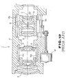
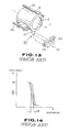
- FIGS. 12 to 14 are directed to the apparatus thus proposed.
- an inner focusing lens barrel 1 has a cylindrical housing 2 which is provided, on front and rear portions thereof, with a focusing lens 3 and a charge coupled device (CCD) 7, respectively.
- CCD charge coupled device
- the focusing lens 3 is the front of the lens barrel 1
- guide shafts 4a, 4a both of which extend axially parallel to the optical axis of the lens barrel, and in front of the CCD 7 are disposed guide shafts 4b, 4b which also extend parallel to the optical axis.
- a lens holder 6 On the guide shafts 4a, 4a is supported a lens holder 6 retaining a variator lens 5 for zooming.
- the lens holder 6 is reciprocally moved on the guide shafts 4a, 4a by manual operation along an optical axis C of the lens barrel 1.
- On the guide shafts 4b, 4b is supported a lens holder 9 retaining a master lens 8 for focusing.
- the lens holder 9 is reciprocally moved on the guide shafts 4b, 4b along the optical axis C by means of a motor M or the like.
- the lens barrel housing 2 is also provided with an apparatus 50 for detecting an initial position of the master lens 8.
- the apparatus 50 consists of an intercept plate 51 and a photo-interrupter 52 having a light-emitting element 53 and a photo-detecting element 54.
- the intercept plate 51 is secured to a lower portion of an outer periphery of the lens holder 9.
- the photo-interrupter 52 is secured at a rear portion of a lower inner-periphery of the housing 2 so as to face the plate 51 upon reciprocating movement of the lens holder 9.
- the elements 53 and 54 are disposed opposite each other in a direction perpendicular to the optical axis C.
- the plate 51 intercepts light emitted from the element 53.
- the photo-detecting element 54 In response to the interception of the emitted light, the photo-detecting element 54 generates an output signal so that an initial position of the master lens 8 is determined on the basis of a position of the lens holder 9.
- the photo-interrupter 52 of the aforementioned apparatus 50 has an output voltage characteristic varying in response to change in environmental temperature, as shown in FIG. 14. This characteristic causes deterioration of lens positioning accuracy.
- the photo-interrupter 52 is not suitable for miniature cameras due to its larger size and further, due to its high manufacturing cost.
- an apparatus 40 for detecting an initial position of a master lens 8 includes a rectangular magnet 41 and a Hall element 42.
- the magnet 41 consists of north- and south-polar magnet halves 41a and 41b which extend outwardly from a lower outer-periphery of the lens holder 9 and are attached together such that their mating faces extend in a longitudinal direction of the lens holder 9.
- the Hall element 42 is secured to a lower inner-periphery of the barrel housing 2 so as to face the north-polar magnet half 41a upon rearward movement of the lens holder 9.
- the Hall element 42 detects magnetic flux generated from the magnet 41 and produces an output signal on the basis of an amount of the detected magnetic flux. On the basis of the produced output signal, an initial position of the lens holder 9, i.e., the master lens 8 mounting the magnet 41 is determined.
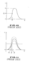
- the Hall element 42 has output voltage characteristic as shown in FIG. 10, in which vertical and longitudinal axes indicate the output voltage (V) and distance (D) between the magnet 41 and the Hall element 42, respectively. In FIG. 10, 1/2 Vo indicating half an amount of a peak voltage Vo is detected by a circuit (not shown) connected to the Hall element 42.
- the output voltage characteristic of the Hall element 42 varies in response to change in environmental temperature, as shown in FIG. 11. Accordingly, an initial position of the lens 8, which is detected upon generation of the initially determined voltage 1/2 Vo, also varies from lo to lo′ or lo ⁇ according to temperature change so that accuracy in positioning of the lens 8 is deteriorated and thereby focusing error is caused in the camera.
- an apparatus for detecting an initial position of a movable lens in a lens barrel in which a lens holder retaining the lens is reciprocally movable parallel with an optical axis of the lens.
- the apparatus includes magnet means which has north and south polarities and is alternatively secured to either an outer periphery of the lens holder or an inner periphery of the lens barrel.
- Magnet flux detecting means is also secured to whichever of the outer periphery of the lens holder or the inner periphery of the lens barrel, to which the magnet means is not secured, such that the detecting means faces a boundary between the magnet halves of the magnet means.
- the detecting means detects magnetic flux density of the magnet means and develops an output voltage based on the detected magnetic flux density.
- the initial position of the lens is determined as a point where the output voltage indicates zero or a value of approximately zero.
- numeral 10 represents an apparatus for detecting an initial position of a movable lens 8 which is disposed in a housing 2 of a lens barrel 1.
- the lens 8 is a master lens retained in a cylindrical lens holder 9 which is supported by guide shafts 4b, 4b so as to be reciprocally movable parallel to an optical axis C of the lens 8.
- the apparatus 10 includes a rectangular magnet 11 and a Hall element 12.
- the magnet 11 consists of north- and south-polar magnet halves 11a and 11b which extend outwardly from a lower outer-periphery of the lens holder 9 and are attached together so as to be aligned in a longitudinal direction of the lens holder 9.
- the Hall element 12 is secured to a lower inner-periphery of the housing 2 so as to face a boundary 11c between the north- and south-polar magnet halves 11a and 11b according to reciprocating movement of the lens holder 9. For instance, after the lens holder 9 is forced to the frontmost or rearmost position by manually, spring force or motor-drive, the magnet 11 on the lens holder 9 moves toward the Hall element 12. Then, the Hall element 12 detects magnetic flux generated from the magnet 11 and develops an output voltage on the basis of an amount of the detected magnetic flux.
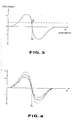
- the output voltage characteristics of the Hall element 12 are shown in FIG. 3, in which vertical and horizontal axes respectively indicate the output voltage (V) and distance (D) between the magnet 11 and the Hall element 12. There are two peaks in the output voltage, one positive, one negative, in the vicinity of a point lo where an output voltage line traverses the horizontal axis. At an intersecting point lo, the Hall element 12 is just opposed to a boundary 11c between the magnet halves 11a and 11b. Accordingly, in a case where a position of the magnet 11 corresponding to the intersecting point lo of FIG. 3 is determined as an initial position of the magnet 11, various positions of the magnet 11 are determined relative to the initial position. Therefore, an initial position of the master lens 8 is determined as well as an initial position of the lens holder 9 mounting the magnet 11. Consequently, by using the intial position of the master lens 8 as a reference, various positions of the lens holder 9 may be determined with high accuracy.
- the Hall element may be connected to a circuit which functions to vertically offset the horizontal axis D where the output voltage indicates zero, for instance, as shown in a dotted line of FIG. 3. Due to this vertical offset of the horizontal axis D, a point lo′ may be employed as the initial position of the master lens 8 instead of the point lo.
- the Hall element 12 has output voltage characteristics varying in response to change in environmental temperature.
- vertical and horizontal axes respectively indicate the output voltage (V) and distance (D) between the magnet 11 and the Hall element 12.
- a position of the lens holder 9 corresponding to the intersecting point lo is determined as an initial position of the master lens 8.
- separate output voltage lines traverse the horizontal axis at substantially the same point lo, while the peaks of the output voltage are different in level. Therefore, the initial position of the master lens 8 is stably determined without influence of change in environmental temperature.
- the apparatus 10 may be considerably improved in view of size, cost and consumption of electric power.
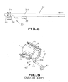
- the magnet 11 utilized in the apparatus of the invention may be of cylindrical shape 21 or trapezoidal shape 21′ as illustrated in FIGS. 5 and 6. Further, as illustrated in FIG. 7, a rectangular magnet 21 ⁇ may be formed by alternately arranging magnet pieces having north- and south polarities and attaching them together.
- the apparatus 30 includes a rectangular bar-like magnet member 31 and a Hall element 32.
- the bar-like magnet member 31 is secured to a lower outer-periphery of the lens holder 9 while the Hall element 32 is mounted on a lower inner-periphery of the housing 2.
- the bar-like magnet member 31 has at least a pair of north- and south-polar end magnets 31a and 31b.
- the Hall element 32 detects magnetic flux generated from the end magnets 31a and 31b and outputs a voltage depending upon change in the detected magnetic flux. At this time, a boundary 31c between the end magnets 31a and 31b is detected as a point where the output voltage from the Hall element 32 indicates zero or approximately zero. As similar to the first embodiment mentioned above, when the Hall element 32 detects the boundary 31c between the end magnets 31a and 31, the corresponding position of the lens holder 9 is determined as an initial position of the lens 8.
- the bar-like magnet member 31 extends forwardly into the front portion of the housing 2 where a lens holder 6 is reciprocally located.
- the bar-like magnet member 31 is also provided, at least in a part opposing to the lens holder 6 located in the front portion of the housing 2, with a plurality of north- and south-polar magnet pieces which are alternately arranged and attached together to form an integral body of the magnet member 31.
- a known MR (magnetoresistive elements) sensor 33 is secured to a front portion of the lower inner-periphery of the housing 2, in which the lens holder 6 retaining a variator lens 5, for example, is reciprocated.
- a position of the variator lens 5 is also determined by detecting addresses or the like corresponding to respective positions of the magnet pieces by means of the MR sensor 33.
- the apparatus of the invention includes a magnetic flux detecting means and north- and south-polar magnets which are alternatively secured to a lens barrel or a lens holder such that the detecting means faces a boundary between north and south poles of the magnet means.
- an initial position of a movable lens in a lens barrel is determined as a position of the lens where an amount of output voltage of the detecting means is approximately zero.
- the apparatus of the invention can be further miniaturized and manufacturing costs and power-consumption can be effectively reduced.
- a magnet means is secured to the lens holder movable within the lens barrel to which a magnetic flux detecting means is secured thereto
- the opposite arrangement may alternatively be employed.
- the detecting means of the invention is not limited to a Hall element.
- the apparatus of the invention may be applicable to a lens holder retaining a variator lens for zooming so that an initial position of the variator lens can be determined.
- the present invention has been described in terms of a video camera but it is noted that the disclosed invention may be further applied to a still camera or other electronic optical system.
Landscapes
- Physics & Mathematics (AREA)
- General Physics & Mathematics (AREA)
- Optics & Photonics (AREA)
- Engineering & Computer Science (AREA)
- Multimedia (AREA)
- Signal Processing (AREA)
- Lens Barrels (AREA)
- Measurement Of Length, Angles, Or The Like Using Electric Or Magnetic Means (AREA)
- Transmission And Conversion Of Sensor Element Output (AREA)
Applications Claiming Priority (2)
| Application Number | Priority Date | Filing Date | Title |
|---|---|---|---|
| JP2294932A JPH04166906A (ja) | 1990-10-31 | 1990-10-31 | レンズ鏡筒の初期位置検出装置 |
| JP294932/90 | 1990-10-31 |
Publications (2)
| Publication Number | Publication Date |
|---|---|
| EP0484250A1 true EP0484250A1 (fr) | 1992-05-06 |
| EP0484250B1 EP0484250B1 (fr) | 1996-02-28 |
Family
ID=17814140
Family Applications (1)
| Application Number | Title | Priority Date | Filing Date |
|---|---|---|---|
| EP91402933A Expired - Lifetime EP0484250B1 (fr) | 1990-10-31 | 1991-10-31 | Appareil pour la détection de la position d'une lentille movible dans un tube de lentille d'une caméra |
Country Status (6)
| Country | Link |
|---|---|
| US (1) | US5432639A (fr) |
| EP (1) | EP0484250B1 (fr) |
| JP (1) | JPH04166906A (fr) |
| KR (1) | KR100195314B1 (fr) |
| DE (1) | DE69117435T2 (fr) |
| SG (1) | SG55154A1 (fr) |
Cited By (5)
| Publication number | Priority date | Publication date | Assignee | Title |
|---|---|---|---|---|
| GB2278928A (en) * | 1993-06-08 | 1994-12-14 | Hughes Aircraft Co | Optical sight with magnetic means indicating field of view selected |
| WO1998013668A1 (fr) * | 1996-09-27 | 1998-04-02 | Robert Bosch Gmbh | Systeme de capteur pour localiser des elements mobiles |
| EP2011400A1 (fr) | 2007-07-06 | 2009-01-07 | INOX Meccanica S.R.L. | Appareil de mise en boyau de produits de viande |
| EP4141537A4 (fr) * | 2020-04-20 | 2024-05-01 | LG Innotek Co., Ltd. | Actionneur de caméra et module de caméra l'incluant |
| US12619128B2 (en) | 2020-04-20 | 2026-05-05 | Lg Innotek Co., Ltd. | Camera actuator and camera module including same |
Families Citing this family (15)
| Publication number | Priority date | Publication date | Assignee | Title |
|---|---|---|---|---|
| JP3352260B2 (ja) * | 1994-12-27 | 2002-12-03 | キヤノン株式会社 | レンズ駆動装置 |
| DE19521654C2 (de) * | 1995-06-14 | 1999-01-07 | Wolf Gmbh Richard | Optische Vorrichtung |
| US5957829A (en) * | 1997-12-17 | 1999-09-28 | Advanced Cardiovascular Systems, Inc. | Apparatus and method for radiotherapy using a radioactive source wire having a magnetic insert |
| JP3597733B2 (ja) * | 1999-08-09 | 2004-12-08 | アルプス電気株式会社 | 磁気式変位検出装置 |
| KR101231482B1 (ko) * | 2004-08-19 | 2013-02-07 | 소니 주식회사 | 위치 검출 기구가 설치된 렌즈 경통 및 촬상 장치 |
| EP1992974B1 (fr) | 2005-01-12 | 2016-01-06 | Trimble Jena GmbH | Dispositif de positionnement |
| JP2006317191A (ja) * | 2005-05-10 | 2006-11-24 | Konica Minolta Opto Inc | 位置検出装置、電子機器 |
| JP2007025069A (ja) * | 2005-07-13 | 2007-02-01 | Sharp Corp | 駆動装置 |
| JP2007041387A (ja) * | 2005-08-04 | 2007-02-15 | Matsushita Electric Ind Co Ltd | 撮像装置及びそれを備えた携帯端末装置 |
| KR101459786B1 (ko) | 2008-10-28 | 2014-11-10 | 삼성전자주식회사 | 카메라 렌즈 어셈블리 및 그의 자동 초점조절 방법 |
| DE102009048272B3 (de) * | 2009-10-05 | 2011-04-21 | Sick Ag | Verfahren zum Positionieren eines magnetischen Sensors |
| CN102565993A (zh) * | 2010-12-07 | 2012-07-11 | 鸿富锦精密工业(深圳)有限公司 | 驱动器、相机模组及便携式电子装置 |
| US10551215B2 (en) * | 2015-06-11 | 2020-02-04 | Analog Devices Global Unlimited Company | Systems, circuits and methods for determining a position of a movable object |
| DE102017003231A1 (de) * | 2017-04-03 | 2018-10-04 | Mühlbauer Gmbh & Co. Kg | Optisches Bauteilerfassungssystem und Verfahren zum Erfassen mindestens eines Bauteils |
| DE102022102664B3 (de) | 2022-02-04 | 2023-08-10 | Precitec Gmbh & Co. Kg | Laserbearbeitungskopf mit hermetisch gekapselter beweglicher Optik |
Citations (2)
| Publication number | Priority date | Publication date | Assignee | Title |
|---|---|---|---|---|
| US4086519A (en) * | 1977-02-25 | 1978-04-25 | Electro-Craft Corporation | Hall effect shaft angle position encoder |
| GB2098743A (en) * | 1981-05-15 | 1982-11-24 | Fuji Heavy Ind Ltd | Magnetic position sensor using hall-effect device |
Family Cites Families (19)
| Publication number | Priority date | Publication date | Assignee | Title |
|---|---|---|---|---|
| US3329833A (en) * | 1967-07-04 | Hall effect transducer for scanning magnetic scale indicia | ||
| US3199630A (en) * | 1958-01-24 | 1965-08-10 | Siemens Ag | Position sensing devices, particularly in hoisting and conveying systems |
| DE1201874B (de) * | 1958-05-22 | 1965-09-30 | Siemens Ag | Wiedergabekopf fuer magnetische Aufzeichnungen |
| US3344347A (en) * | 1963-08-23 | 1967-09-26 | Bell Inc F W | Method and apparatus for determining displacement utilizing a hall plate positioned tangential to an arcuate magnetic field |
| DE1303818C2 (de) * | 1966-09-22 | 1973-08-02 | Siemens Ag | Analoger hysteresefreier weggeber mit hallgenerator |
| US4043642A (en) * | 1973-03-06 | 1977-08-23 | Canon Kabushiki Kaisha | Zoom lens system having electrical control of moving elements |
| FR2331774A1 (fr) * | 1975-11-12 | 1977-06-10 | Radiotechnique Compelec | Procede de reperage dynamique de positions particulieres de pieces mobiles a l'aide d'un cristal a effet hall et dispositifs de mise en oeuvre du procede |
| US4318038A (en) * | 1978-11-15 | 1982-03-02 | Nippon Electric Co., Ltd. | Moving-coil linear motor |
| GB2052855B (en) * | 1979-03-30 | 1983-05-18 | Sony Corp | Magnetoresistive transducers |
| GB2071333B (en) * | 1980-02-22 | 1984-02-01 | Sony Corp | Magnetic sensor device |
| US4403515A (en) * | 1980-08-29 | 1983-09-13 | Aisin Seiki Company, Limited | Position sensor |
| US4325614A (en) * | 1980-12-16 | 1982-04-20 | Polaroid Corporation | Exposure control system with shutter operation controlled by a microcomputer |
| US4658214A (en) * | 1982-12-28 | 1987-04-14 | Polaroid Corporation | Magnetic position indicator using multiple probes |
| US4750821A (en) * | 1984-08-24 | 1988-06-14 | Canon Kabushiki Kaisha | Zoom lens assembly |
| JPS61245121A (ja) * | 1985-04-23 | 1986-10-31 | Victor Co Of Japan Ltd | ズ−ムレンズ装置 |
| JPH0648888B2 (ja) * | 1988-06-27 | 1994-06-22 | 松下電工株式会社 | 床スラブの電線菅装置 |
| JPH0213216U (fr) * | 1988-07-08 | 1990-01-26 | ||
| US4996545A (en) * | 1989-04-03 | 1991-02-26 | Asahi Kogaku Kogyo Kabushiki Kaisha | Apparatus for correcting blurred image of camera using angular acceleration sensor and angular acceleration sensor |
| JPH04119306A (ja) * | 1990-09-10 | 1992-04-20 | Sony Corp | カメラ用レンズ鏡筒 |
-
1990
- 1990-10-31 JP JP2294932A patent/JPH04166906A/ja active Pending
-
1991
- 1991-09-27 KR KR1019910016834A patent/KR100195314B1/ko not_active Expired - Fee Related
- 1991-10-31 DE DE69117435T patent/DE69117435T2/de not_active Expired - Fee Related
- 1991-10-31 EP EP91402933A patent/EP0484250B1/fr not_active Expired - Lifetime
- 1991-10-31 SG SG1996008212A patent/SG55154A1/en unknown
-
1993
- 1993-10-12 US US08/135,183 patent/US5432639A/en not_active Expired - Lifetime
Patent Citations (2)
| Publication number | Priority date | Publication date | Assignee | Title |
|---|---|---|---|---|
| US4086519A (en) * | 1977-02-25 | 1978-04-25 | Electro-Craft Corporation | Hall effect shaft angle position encoder |
| GB2098743A (en) * | 1981-05-15 | 1982-11-24 | Fuji Heavy Ind Ltd | Magnetic position sensor using hall-effect device |
Non-Patent Citations (3)
| Title |
|---|
| PATENT ABSTRACTS OF JAPAN vol. 11, no. 110 (E-496)(2557) 7 April 1987 & JP-A-61 256 870 ( MATSUSHITA ELECTRIC IND CO LTD ) 14 November 1986 * |
| PATENT ABSTRACTS OF JAPAN vol. 14, no. 25 (P-991)(3968) 18 January 1990 & JP-A-1 265 214 ( HITACHI ) 23 October 1989 * |
| PATENT ABSTRACTS OF JAPAN vol. 6, no. 198 (P-147)(1076) 7 October 1982 & JP-A-57 108 806 ( OLYMPUS KOGAKU KOGYO K.K. ) 7 July 1982 * |
Cited By (7)
| Publication number | Priority date | Publication date | Assignee | Title |
|---|---|---|---|---|
| GB2278928A (en) * | 1993-06-08 | 1994-12-14 | Hughes Aircraft Co | Optical sight with magnetic means indicating field of view selected |
| GB2278928B (en) * | 1993-06-08 | 1996-07-31 | Hughes Aircraft Co | Optical sight with magnetic means indicating field of view selected |
| US5548442A (en) * | 1993-06-08 | 1996-08-20 | Hughes Aircraft Company | Optical sight assembly |
| WO1998013668A1 (fr) * | 1996-09-27 | 1998-04-02 | Robert Bosch Gmbh | Systeme de capteur pour localiser des elements mobiles |
| EP2011400A1 (fr) | 2007-07-06 | 2009-01-07 | INOX Meccanica S.R.L. | Appareil de mise en boyau de produits de viande |
| EP4141537A4 (fr) * | 2020-04-20 | 2024-05-01 | LG Innotek Co., Ltd. | Actionneur de caméra et module de caméra l'incluant |
| US12619128B2 (en) | 2020-04-20 | 2026-05-05 | Lg Innotek Co., Ltd. | Camera actuator and camera module including same |
Also Published As
| Publication number | Publication date |
|---|---|
| DE69117435T2 (de) | 1996-10-24 |
| US5432639A (en) | 1995-07-11 |
| DE69117435D1 (de) | 1996-04-04 |
| JPH04166906A (ja) | 1992-06-12 |
| EP0484250B1 (fr) | 1996-02-28 |
| SG55154A1 (en) | 1998-12-21 |
| KR920008516A (ko) | 1992-05-28 |
| KR100195314B1 (ko) | 1999-06-15 |
Similar Documents
| Publication | Publication Date | Title |
|---|---|---|
| US5432639A (en) | Apparatus for detecting an initial position of a movable lens in a lens barrel of a camera | |
| JP5797627B2 (ja) | 撮像装置 | |
| US7623151B2 (en) | Vibration correcting device, lens barrel, and optical device | |
| JP5997992B2 (ja) | 撮像装置 | |
| EP3584624B1 (fr) | Dispositif d'entraînement de système de réflexion ayant une structure à axes multiples | |
| US11397308B2 (en) | Camera module and operation method therefor | |
| US20140002912A1 (en) | Lens drive device and imaging device | |
| JP2003295249A (ja) | レンズ鏡筒およびこれを用いた光学機器 | |
| US20250093616A1 (en) | Imaging lens module and electronic device | |
| CN211061758U (zh) | 一种变焦镜头 | |
| US4519691A (en) | Photographic taking lens driving means | |
| JP4483950B2 (ja) | レンズ鏡筒および撮像装置 | |
| JP5997993B2 (ja) | 撮像装置 | |
| KR20200060201A (ko) | 카메라 모듈 | |
| US8411381B2 (en) | Lens barrel | |
| CN218158491U (zh) | 透镜组驱动装置和自动聚焦镜头 | |
| EP3764636B1 (fr) | Procédé d'étalonnage de dispositif appareil photo | |
| JP2009204941A (ja) | レンズ鏡筒及びそれを有する光学機器 | |
| EP1781021A2 (fr) | Monture d'objectif et appareil de prise de vue | |
| JP2002214501A (ja) | 位置検出センサを有する装置および光学装置 | |
| WO2025054932A1 (fr) | Actionneur pour caméra, module de caméra et appareil d'imagerie | |
| JPH05196853A (ja) | レンズ鏡筒の初期位置検出装置 | |
| JP2008026882A (ja) | 位置決め装置、ブレ補正装置、電子機器、及び、位置決め装置の製造方法 | |
| KR20220052633A (ko) | 렌즈구동장치 | |
| JP2733585B2 (ja) | レンズ鏡筒 |
Legal Events
| Date | Code | Title | Description |
|---|---|---|---|
| PUAI | Public reference made under article 153(3) epc to a published international application that has entered the european phase |
Free format text: ORIGINAL CODE: 0009012 |
|
| AK | Designated contracting states |
Kind code of ref document: A1 Designated state(s): DE FR GB |
|
| 17P | Request for examination filed |
Effective date: 19921022 |
|
| 17Q | First examination report despatched |
Effective date: 19940406 |
|
| GRAA | (expected) grant |
Free format text: ORIGINAL CODE: 0009210 |
|
| AK | Designated contracting states |
Kind code of ref document: B1 Designated state(s): DE FR GB |
|
| REF | Corresponds to: |
Ref document number: 69117435 Country of ref document: DE Date of ref document: 19960404 |
|
| ET | Fr: translation filed | ||
| PLBE | No opposition filed within time limit |
Free format text: ORIGINAL CODE: 0009261 |
|
| STAA | Information on the status of an ep patent application or granted ep patent |
Free format text: STATUS: NO OPPOSITION FILED WITHIN TIME LIMIT |
|
| 26N | No opposition filed | ||
| PGFP | Annual fee paid to national office [announced via postgrant information from national office to epo] |
Ref country code: FR Payment date: 20011010 Year of fee payment: 11 |
|
| PGFP | Annual fee paid to national office [announced via postgrant information from national office to epo] |
Ref country code: GB Payment date: 20011031 Year of fee payment: 11 |
|
| PGFP | Annual fee paid to national office [announced via postgrant information from national office to epo] |
Ref country code: DE Payment date: 20011112 Year of fee payment: 11 |
|
| REG | Reference to a national code |
Ref country code: GB Ref legal event code: IF02 |
|
| PG25 | Lapsed in a contracting state [announced via postgrant information from national office to epo] |
Ref country code: GB Free format text: LAPSE BECAUSE OF NON-PAYMENT OF DUE FEES Effective date: 20021031 |
|
| PG25 | Lapsed in a contracting state [announced via postgrant information from national office to epo] |
Ref country code: DE Free format text: LAPSE BECAUSE OF NON-PAYMENT OF DUE FEES Effective date: 20030501 |
|
| GBPC | Gb: european patent ceased through non-payment of renewal fee | ||
| PG25 | Lapsed in a contracting state [announced via postgrant information from national office to epo] |
Ref country code: FR Free format text: LAPSE BECAUSE OF NON-PAYMENT OF DUE FEES Effective date: 20030630 |
|
| REG | Reference to a national code |
Ref country code: FR Ref legal event code: ST |