EP0484341B1 - Eine leistungsversorgung - Google Patents
Eine leistungsversorgung Download PDFInfo
- Publication number
- EP0484341B1 EP0484341B1 EP90909096A EP90909096A EP0484341B1 EP 0484341 B1 EP0484341 B1 EP 0484341B1 EP 90909096 A EP90909096 A EP 90909096A EP 90909096 A EP90909096 A EP 90909096A EP 0484341 B1 EP0484341 B1 EP 0484341B1
- Authority
- EP
- European Patent Office
- Prior art keywords
- power supply
- line
- circuit breaker
- leads
- fault detection
- Prior art date
- Legal status (The legal status is an assumption and is not a legal conclusion. Google has not performed a legal analysis and makes no representation as to the accuracy of the status listed.)
- Expired - Lifetime
Links
- 238000001514 detection method Methods 0.000 claims abstract description 18
- 239000003990 capacitor Substances 0.000 claims abstract description 16
- 230000007935 neutral effect Effects 0.000 claims description 9
- 238000012360 testing method Methods 0.000 claims description 8
- 230000001629 suppression Effects 0.000 claims description 2
- 239000007787 solid Substances 0.000 claims 1
- 230000001052 transient effect Effects 0.000 claims 1
- 238000002955 isolation Methods 0.000 abstract description 4
- 230000008878 coupling Effects 0.000 abstract description 2
- 238000010168 coupling process Methods 0.000 abstract description 2
- 238000005859 coupling reaction Methods 0.000 abstract description 2
- 238000010586 diagram Methods 0.000 description 4
- 238000010276 construction Methods 0.000 description 2
- 230000001960 triggered effect Effects 0.000 description 2
- 230000000903 blocking effect Effects 0.000 description 1
- 238000009434 installation Methods 0.000 description 1
- 238000009413 insulation Methods 0.000 description 1
- 238000012986 modification Methods 0.000 description 1
- 230000004048 modification Effects 0.000 description 1
- 230000001681 protective effect Effects 0.000 description 1
- 238000004804 winding Methods 0.000 description 1
Images



Classifications
-
- H—ELECTRICITY
- H02—GENERATION; CONVERSION OR DISTRIBUTION OF ELECTRIC POWER
- H02H—EMERGENCY PROTECTIVE CIRCUIT ARRANGEMENTS
- H02H1/00—Details of emergency protective circuit arrangements
- H02H1/06—Arrangements for supplying operative power
Definitions
- the present invention relates to power supplies for DC equipment such as electronic circuits. More specifically the invention relates to a power supply incorporating a fault detection circuit controlling a circuit breaker.
- US-A-3611076 discloses a power supply incorporating a circuit breaker and fault dection circuit.
- US-A-4412278 discloses AC to DC rectification with a polarised capacitor of large value coupled to a line.
- a low current power supply incorporating a circuit breaker and fault detection circuit means for supplying tripping energy for said circuit breaker, said power supply being subject to dielectric testing with a high DC voltage, comprising: line and neutral power leads and rectifier means coupled to said line and neutral power leads for supplying power to said fault detection circuit means characterised by a capacitor, on the order of 0.1 microfarads, individually coupled between each of said line power leads and said rectifier means for protecting said power supply from said high DC voltage.
- An object of the present invention is to provide a power supply having DC dielectric test protection and that is capable of driving a fault detection circuit and associated power supply.
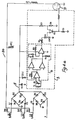
- the power supply 1 incorporates a circuit breaker including an SCR Q2 and an associated solenoid 2, the SCR Q2 being controlled by a ground fault detection circuit 3 which is indicated by interrupted lines in Fig. 1.
- the power supply 1 is connected to a three phase supply and includes line leads A, B and C and a neutral lead N.
- Line leads A and B are connected to a full wave bridge rectifier comprising diodes D1 to D4.
- the line lead C together with the neutral lead N are the input of a second full wave bridge rectifier formed by diodes D5 to D8.
- the outputs of the rectifiers are interconnected at an output lead 5 and the negative outputs are earthed.
- the output lead 5 drives the ground fault detection circuit 3 and is also connected to the solenoid 2 to provide tripping energy for the circuit breaker.
- a storage capacitor C4 and a Zener diode ZD1 are connected across the bridge rectifier output.
- the line leads A, B and C include coupling capacitors C1, C2 and C3 respectively for DC isolation.
- the ground fault detection circuit 3 is of conventional construction and comprises a current transformer T1 having a pair of opposed primary windings connected to a comparator circuit connected at it's output to a variable resistor R6.
- the variable resistor R6 is connected by a forward blocking diode D9 to a capacitor C20 which is in turn connected to an amplifier Q1.
- the output of the amplifier Q1 is connected to the gate of the SCR Q2.
- the comparator 6 output On detection of a ground fault, the comparator 6 output is high and the capacitor C20 charges through R6 so that the SCR Q2 is triggered by the amplifier Q1.
- the power supply 1 is used to provide power to electronic or other devices that are subjected to DC insulation or dielectric tests, commonly referred to as "megger" tests.
- the capacitors C1, C2 and C3 provide isolation during such tests and each has a value of 0.1 microfarad, giving an AC impedance of approximately 26.5 k ohms at 60 Hz. Accordingly, only several milliamperes of current is supplied to the circuit. In this way, isolation is provided from a high DC voltage applied to the power supply while sufficient current is provided to operate the sensing and delay function of the circuit breaker and the ground fault detection circuit 3. A certain amount of energy is stored in the storage capacitor C4 to assist in maintaining the SCR Q2 in conduction on tripping of the circuit breaker.
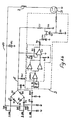
- Fig. 2 there is illustrated an alternative power supply generally by the reference numeral 10. Parts similar to those described with reference to Fig. 1 are identified similarly. The only difference between the power supply 10 and the power supply 1 is that an additional reservoir capacitor C12 is connected across the rectifier output for provision of additional tripping energy. The reservoir capacitor C12 causes a time delay in tripping of the circuit breaker. This arrangement is suitable when significantly more current is required during the tripping operation.
- Fig. 3 there is illustrated a further power supply according to the invention indicated generally by the reference numeral 20. Parts similar to those described with reference to the previous drawings are identified similarly.
- the important feature of the power supply 20 is that the line leads A, B and C are connected directly to the circuit breaker solenoid 2 to provide the tripping energy.
- the connection is made by a lead 21 to which each of the line leads A, B and C is connected through diodes D10, D11, and D12 respectively.
- the lead 21 includes a spike suppression varistor VR1.
- the rectifier output lead 5 is also connected to the solenoid 2 through a diode D13 and a resistor R11.
- the power supply 20 provides the tripping energy only when it is needed.
- the tripping energy is supplied from the line leads A, B and C.
- a limited amount of energy is stored in the storage capacitor C4 and this is used to maintain the SCR Q2 in conduction. It has been found that although the solenoid 2 only has a half wave input, sufficient energy is provided for it's operation. If the SCR Q2 were triggered between positive half cycles, and one of the three phases were not energized, the SCR Q2 would be turned on and held in the conducting state by current supplied through the diode D13 and the resistor R11 from the storage capacitor C4.
- the power supply 30 includes a circuit breaker having a VMOS transistor 31 instead of an SCR.
- the VMOS transistor 31 turns off after a predetermined time, there is no need for the rectifier output lead 5 to be connected to maintain it in conduction.
- This arrangement allows the power supply to be connected to either the line or the load end of the interrupter contacts. This is an advantage over the use of an SCR, because when an SCR is used, the connection must be made on the load side of the interrupter so that the voltage source will be removed when tripping occurs. If such power supplies are connected on the line side of the interrupter, the tripping device would be continually energized after tripping. This could lead to "burnout".
- the power supplies described above have four wire, three phase connections and thus operate if any one of the phases and neutral is present.
- the power supply 40 of Fig. 4(b) operates with a three wire, three phase connection and will thus operate with two of the three phases present. Only one bridge rectifier is used and this is connected to the line leads A and B, the line lead C being connected through a diode D40 to the rectifier output lead 5.
- the power supply will operate if any one of the phases and neutral are present and thus will not operate without the neutral.
- the circuit of Fig. 4(b), however, will operate if any two lines are present.
- the invention provides a power supply which in a simple manner includes protection against applied DC and is also arranged to supply a fault detection circuit and circuit breaker with sufficient tripping energy.
Landscapes
- Emergency Protection Circuit Devices (AREA)
- Treatments For Attaching Organic Compounds To Fibrous Goods (AREA)
Claims (5)
- Eine Schwachstrom-Leistungsversorgung, die einen Leistungsschutzschalter (2) und eine Einrichtung für einen Fehlerstromschutzschalter (3) zur Lieferung von Auslösespannung für den genannten Leistungsschutzschalter (2) umfaßt, wobei die genannte Leistungsversorgung Isolationsprüfungen mit einer hohen Gleichstromspannung unterworfen ist, und folgendes aufweist:
Phasen- (A, B, C) und Neutralleitungen (N); und Gleichrichtereinrichtungen (D1 bis D8), die mit den genannten Phasen- (A, B, C) und Neutralleitungen (N) zur Lieferung von Strom an die genannte Fehlerstromschutzvorrichtung (3) verbunden sind; charakterisiert durch
einen Kondensator (C1, C2, C3) um den Wert von 0,1 Microfarad, der individuell an jede der genannten Phasenleitungen (A, B, C) und die genannten Leistungsversorgung von der hohen Gleichstromspannung angeschlossen ist. - Eine Leistungsversorgung nach Anspruch 1, charakterisiert durch weiteren Einbau eines Solenoid (2) in den genannten Leistungsschutzschalter, der mit der genannten Fehlerstromschutzvorrichtung (3) verbunden ist.
- Eine Leistungsversorgung nach Anspruch 2, dadurch charakterisiert, daß der genannte Solenoid 92) durch zusätzliche Gleichrichtervorrichtungen (D10, D11, D12) mit den genannten Phasenleitungen (A, B, C) verbunden ist.
- Eine Leistungsversorgung nach Anspruch 3, dadurch gekennzeichnet, daß die genannte Fehlerstromschutzvorrichtung (3) einen Halbleiterschalter (Q2, 31) in Reihe mit dem genannten Solenoid (2() beinhaltet.
- Eine Leistungsversorgung nach Anspruch 4, charakterisiert durch weiteren Einbau einer Einrichtung zur Unterdrückung von Spannungsspitzen (VR1), das an die genannten Phasenleitungen (A, B, C) angeschlossen ist.
Applications Claiming Priority (3)
| Application Number | Priority Date | Filing Date | Title |
|---|---|---|---|
| US34032389A | 1989-04-19 | 1989-04-19 | |
| PCT/US1990/002794 WO1991018441A1 (en) | 1989-04-19 | 1990-05-22 | A power supply |
| US07/552,374 US5016135A (en) | 1989-04-19 | 1990-07-16 | Power supply incorporating circuit breaker and fault detection circuit |
Publications (3)
| Publication Number | Publication Date |
|---|---|
| EP0484341A1 EP0484341A1 (de) | 1992-05-13 |
| EP0484341A4 EP0484341A4 (en) | 1993-06-09 |
| EP0484341B1 true EP0484341B1 (de) | 1994-12-28 |
Family
ID=26992062
Family Applications (1)
| Application Number | Title | Priority Date | Filing Date |
|---|---|---|---|
| EP90909096A Expired - Lifetime EP0484341B1 (de) | 1989-04-19 | 1990-05-22 | Eine leistungsversorgung |
Country Status (5)
| Country | Link |
|---|---|
| US (1) | US5016135A (de) |
| EP (1) | EP0484341B1 (de) |
| JP (1) | JP2719441B2 (de) |
| DE (1) | DE69015640T2 (de) |
| WO (1) | WO1991018441A1 (de) |
Cited By (1)
| Publication number | Priority date | Publication date | Assignee | Title |
|---|---|---|---|---|
| CN102347754A (zh) * | 2010-08-03 | 2012-02-08 | 黄华道 | 光控开关电路 |
Families Citing this family (11)
| Publication number | Priority date | Publication date | Assignee | Title |
|---|---|---|---|---|
| US5095398A (en) * | 1990-02-12 | 1992-03-10 | Square D Company | Electrical circuit breaker protection device |
| JP2591311B2 (ja) * | 1990-10-12 | 1997-03-19 | 日本電気株式会社 | インダクタンス負荷駆動回路 |
| EP0529949B1 (de) * | 1991-08-27 | 1996-06-26 | AT&T Corp. | Gleichtaktüberspannungsschutzschaltung |
| US5598315A (en) * | 1993-10-27 | 1997-01-28 | Square D Company | Self-power tripping relay with balanced power supply current and measurement current |
| US5774319A (en) * | 1993-10-27 | 1998-06-30 | Square D Company | Energy validation arrangement for a self-powered circuit interrupter |
| US5668692A (en) * | 1993-10-27 | 1997-09-16 | Square D Company | Self-powered circuit interruption arrangement |
| DE19809783A1 (de) * | 1998-03-07 | 1999-09-09 | Metabowerke Kg | Elektrowerkzeug mit Ableitstromsensorik |
| US5959819A (en) * | 1998-03-16 | 1999-09-28 | Eaton Corporation | Reliable fault tolerant power supply for a protective relay |
| FI122449B (fi) * | 2009-08-18 | 2012-01-31 | Vacon Oyj | Suuntaajalaite |
| US8254072B2 (en) * | 2009-11-05 | 2012-08-28 | Schneider Electric USA, Inc. | Electrical load center |
| KR101879340B1 (ko) * | 2017-01-05 | 2018-07-17 | 엘에스산전 주식회사 | 3상전원 부족전압 트립장치 |
Family Cites Families (13)
| Publication number | Priority date | Publication date | Assignee | Title |
|---|---|---|---|---|
| US3379939A (en) * | 1965-10-21 | 1968-04-23 | Texas Instruments Inc | Fail safe controller |
| US3611076A (en) * | 1970-01-27 | 1971-10-05 | Gen Electric | Overload protection of multiple devices with a single circuit breaker |
| US3671815A (en) * | 1972-06-20 | 1972-06-20 | Columbia Gas Syst | Flame detection apparatus |
| US4042964A (en) * | 1975-12-15 | 1977-08-16 | Robertshaw Controls Company | Motor protection circuit |
| US4068276A (en) * | 1976-07-14 | 1978-01-10 | Interelectronics Corporation | Protective system for electrical appliances |
| NL176508C (nl) * | 1977-06-14 | 1985-04-16 | Hazemeijer Bv | Voedingsapparaat voor een beveiligingsinrichting, zoals een aardlekdetectie-inrichting, benevens met een dergelijk voedingsapparaat uitgeruste beveiligingsinrichting. |
| US4258403A (en) * | 1979-05-31 | 1981-03-24 | Westinghouse Electric Corp. | Ground fault circuit interrupter |
| US4412278A (en) * | 1982-01-12 | 1983-10-25 | International Business Machines Corporation | Ac-to-dc converter using polarized input isolation capacitors |
| US4584623A (en) * | 1983-11-07 | 1986-04-22 | Watsco, Inc. | Electrical load protection device |
| GB8404766D0 (en) * | 1984-02-23 | 1984-03-28 | Delta Electrical Holdings | Earth leakage protective circuit |
| GB2162708B (en) * | 1984-07-27 | 1988-12-14 | Technology Res Corp | Ground fault current interrupter circuit with open neutral, and ground lead protection |
| US4598331A (en) * | 1984-07-30 | 1986-07-01 | Technology Research Corporation | Ground fault current interrupter circuit with open neutral and ground lead protection |
| US4734817A (en) * | 1984-11-09 | 1988-03-29 | Pt Components, Inc. | Magnetic clutch |
-
1990
- 1990-05-22 WO PCT/US1990/002794 patent/WO1991018441A1/en not_active Ceased
- 1990-05-22 EP EP90909096A patent/EP0484341B1/de not_active Expired - Lifetime
- 1990-05-22 JP JP2508748A patent/JP2719441B2/ja not_active Expired - Fee Related
- 1990-05-22 DE DE69015640T patent/DE69015640T2/de not_active Expired - Fee Related
- 1990-07-16 US US07/552,374 patent/US5016135A/en not_active Expired - Fee Related
Cited By (2)
| Publication number | Priority date | Publication date | Assignee | Title |
|---|---|---|---|---|
| CN102347754A (zh) * | 2010-08-03 | 2012-02-08 | 黄华道 | 光控开关电路 |
| CN102347754B (zh) * | 2010-08-03 | 2013-07-24 | 黄华道 | 光控开关电路 |
Also Published As
| Publication number | Publication date |
|---|---|
| EP0484341A4 (en) | 1993-06-09 |
| US5016135A (en) | 1991-05-14 |
| WO1991018441A1 (en) | 1991-11-28 |
| JP2719441B2 (ja) | 1998-02-25 |
| DE69015640T2 (de) | 1995-05-24 |
| EP0484341A1 (de) | 1992-05-13 |
| DE69015640D1 (de) | 1995-02-09 |
| JPH05500745A (ja) | 1993-02-12 |
Similar Documents
| Publication | Publication Date | Title |
|---|---|---|
| US4931893A (en) | Loss of neutral or ground protection circuit | |
| US4955069A (en) | A.C. power controller with short circuit and overload protection | |
| US5337206A (en) | Three phase power monitor | |
| EP0484341B1 (de) | Eine leistungsversorgung | |
| US4999728A (en) | Power surge protection circuit | |
| CN1116741A (zh) | 高功率因数负荷的交流线路稳定化电路 | |
| US3280374A (en) | Electrical recycling circuit for controlling and protecting functional equipment | |
| CA2064027C (en) | Ground fault circuit interrupter | |
| US5488303A (en) | GFCI with auxiliary coil current blocking means and improved test button configuration | |
| US4466039A (en) | Open circuit current transformer protection circuit | |
| US3979644A (en) | Overvoltage protection arrangement | |
| GB2224404A (en) | Residual current device with missing neutral protection | |
| RU2374734C2 (ru) | Защитная схема для искробезопасных электромагнитных исполнительных устройств и защитная схема для искробезопасных систем энергоснабжения | |
| IE70222B1 (en) | A power supply | |
| KR0123006B1 (ko) | 전력변환장치 | |
| EP1107415A2 (de) | Fehlerstromschutzschalter | |
| CA2018831A1 (en) | A.c. power controller with short circuit and overload protection | |
| JPH02179219A (ja) | 電源装置 | |
| CA2063561A1 (en) | Power supply | |
| JPH0884479A (ja) | スイッチング回路の安全装置 | |
| JPS63262022A (ja) | 漏電保護回路 | |
| US3093771A (en) | A. c. modulator protective device | |
| IE67969B1 (en) | A loss of neutral or ground protection circuit | |
| SU832644A2 (ru) | Устройство дл дифференциальнойзАщиТы учАСТКОВ СЕТи пОСТО ННОгО TOKA | |
| KR0111711Y1 (ko) | 과전류 차단회로 |
Legal Events
| Date | Code | Title | Description |
|---|---|---|---|
| PUAI | Public reference made under article 153(3) epc to a published international application that has entered the european phase |
Free format text: ORIGINAL CODE: 0009012 |
|
| 17P | Request for examination filed |
Effective date: 19920211 |
|
| AK | Designated contracting states |
Kind code of ref document: A1 Designated state(s): DE FR GB IT |
|
| A4 | Supplementary search report drawn up and despatched |
Effective date: 19930419 |
|
| AK | Designated contracting states |
Kind code of ref document: A4 Designated state(s): DE FR GB IT |
|
| 17Q | First examination report despatched |
Effective date: 19931118 |
|
| GRAA | (expected) grant |
Free format text: ORIGINAL CODE: 0009210 |
|
| ITF | It: translation for a ep patent filed | ||
| REF | Corresponds to: |
Ref document number: 69015640 Country of ref document: DE Date of ref document: 19950209 |
|
| ET | Fr: translation filed | ||
| PLBE | No opposition filed within time limit |
Free format text: ORIGINAL CODE: 0009261 |
|
| STAA | Information on the status of an ep patent application or granted ep patent |
Free format text: STATUS: NO OPPOSITION FILED WITHIN TIME LIMIT |
|
| 26N | No opposition filed | ||
| REG | Reference to a national code |
Ref country code: GB Ref legal event code: IF02 |
|
| PGFP | Annual fee paid to national office [announced via postgrant information from national office to epo] |
Ref country code: GB Payment date: 20020404 Year of fee payment: 13 |
|
| PGFP | Annual fee paid to national office [announced via postgrant information from national office to epo] |
Ref country code: FR Payment date: 20020503 Year of fee payment: 13 |
|
| PGFP | Annual fee paid to national office [announced via postgrant information from national office to epo] |
Ref country code: DE Payment date: 20020531 Year of fee payment: 13 |
|
| PG25 | Lapsed in a contracting state [announced via postgrant information from national office to epo] |
Ref country code: GB Free format text: LAPSE BECAUSE OF NON-PAYMENT OF DUE FEES Effective date: 20030522 |
|
| PG25 | Lapsed in a contracting state [announced via postgrant information from national office to epo] |
Ref country code: DE Free format text: LAPSE BECAUSE OF NON-PAYMENT OF DUE FEES Effective date: 20031202 |
|
| GBPC | Gb: european patent ceased through non-payment of renewal fee |
Effective date: 20030522 |
|
| PG25 | Lapsed in a contracting state [announced via postgrant information from national office to epo] |
Ref country code: FR Free format text: LAPSE BECAUSE OF NON-PAYMENT OF DUE FEES Effective date: 20040130 |
|
| REG | Reference to a national code |
Ref country code: FR Ref legal event code: ST |
|
| PG25 | Lapsed in a contracting state [announced via postgrant information from national office to epo] |
Ref country code: IT Free format text: LAPSE BECAUSE OF NON-PAYMENT OF DUE FEES;WARNING: LAPSES OF ITALIAN PATENTS WITH EFFECTIVE DATE BEFORE 2007 MAY HAVE OCCURRED AT ANY TIME BEFORE 2007. THE CORRECT EFFECTIVE DATE MAY BE DIFFERENT FROM THE ONE RECORDED. Effective date: 20050522 |