EP0484483B1 - Connecteur de stimulateur cardiaque moule a parties multiples, procede de fabrication et ensemble matriciel de stimulateur cardiaque - Google Patents
Connecteur de stimulateur cardiaque moule a parties multiples, procede de fabrication et ensemble matriciel de stimulateur cardiaque Download PDFInfo
- Publication number
- EP0484483B1 EP0484483B1 EP91909089A EP91909089A EP0484483B1 EP 0484483 B1 EP0484483 B1 EP 0484483B1 EP 91909089 A EP91909089 A EP 91909089A EP 91909089 A EP91909089 A EP 91909089A EP 0484483 B1 EP0484483 B1 EP 0484483B1
- Authority
- EP
- European Patent Office
- Prior art keywords
- connector
- pacemaker
- entrance
- ring
- tip
- Prior art date
- Legal status (The legal status is an assumption and is not a legal conclusion. Google has not performed a legal analysis and makes no representation as to the accuracy of the status listed.)
- Expired - Lifetime
Links
- 238000004519 manufacturing process Methods 0.000 title claims description 21
- 239000004020 conductor Substances 0.000 claims abstract description 70
- 229920000642 polymer Polymers 0.000 claims description 33
- 238000000034 method Methods 0.000 claims description 28
- 238000007789 sealing Methods 0.000 claims description 24
- 238000005304 joining Methods 0.000 claims description 19
- 239000004593 Epoxy Substances 0.000 claims description 8
- 238000005266 casting Methods 0.000 claims description 7
- 210000001124 body fluid Anatomy 0.000 claims description 6
- 239000007788 liquid Substances 0.000 claims description 6
- 238000000465 moulding Methods 0.000 claims description 6
- 239000007787 solid Substances 0.000 claims description 6
- 239000000463 material Substances 0.000 claims description 5
- 229920002492 poly(sulfone) Polymers 0.000 claims description 4
- 238000010276 construction Methods 0.000 claims description 2
- 229920002379 silicone rubber Polymers 0.000 claims description 2
- 239000000560 biocompatible material Substances 0.000 claims 1
- 229920001940 conductive polymer Polymers 0.000 claims 1
- 238000010348 incorporation Methods 0.000 abstract 1
- 238000003780 insertion Methods 0.000 description 7
- 230000037431 insertion Effects 0.000 description 7
- 238000003754 machining Methods 0.000 description 5
- 239000010839 body fluid Substances 0.000 description 4
- 239000010935 stainless steel Substances 0.000 description 3
- 229910001220 stainless steel Inorganic materials 0.000 description 3
- 210000001519 tissue Anatomy 0.000 description 3
- 238000003466 welding Methods 0.000 description 3
- 230000000747 cardiac effect Effects 0.000 description 2
- 230000006835 compression Effects 0.000 description 2
- 238000007906 compression Methods 0.000 description 2
- 238000000605 extraction Methods 0.000 description 2
- 238000001746 injection moulding Methods 0.000 description 2
- 230000014759 maintenance of location Effects 0.000 description 2
- 239000002991 molded plastic Substances 0.000 description 2
- 230000002747 voluntary effect Effects 0.000 description 2
- 210000001015 abdomen Anatomy 0.000 description 1
- 210000000577 adipose tissue Anatomy 0.000 description 1
- 229910045601 alloy Inorganic materials 0.000 description 1
- 239000000956 alloy Substances 0.000 description 1
- 239000008280 blood Substances 0.000 description 1
- 210000004369 blood Anatomy 0.000 description 1
- 210000000481 breast Anatomy 0.000 description 1
- 238000003486 chemical etching Methods 0.000 description 1
- 230000007797 corrosion Effects 0.000 description 1
- 238000005260 corrosion Methods 0.000 description 1
- 238000010586 diagram Methods 0.000 description 1
- 235000012489 doughnuts Nutrition 0.000 description 1
- 239000003814 drug Substances 0.000 description 1
- 229940079593 drug Drugs 0.000 description 1
- 210000005003 heart tissue Anatomy 0.000 description 1
- 230000004118 muscle contraction Effects 0.000 description 1
- 230000000638 stimulation Effects 0.000 description 1
- 238000002560 therapeutic procedure Methods 0.000 description 1
- 210000003462 vein Anatomy 0.000 description 1
- 210000002620 vena cava superior Anatomy 0.000 description 1
Images


Classifications
-
- H—ELECTRICITY
- H01—ELECTRIC ELEMENTS
- H01R—ELECTRICALLY-CONDUCTIVE CONNECTIONS; STRUCTURAL ASSOCIATIONS OF A PLURALITY OF MUTUALLY-INSULATED ELECTRICAL CONNECTING ELEMENTS; COUPLING DEVICES; CURRENT COLLECTORS
- H01R13/00—Details of coupling devices of the kinds covered by groups H01R12/70 or H01R24/00 - H01R33/00
- H01R13/46—Bases; Cases
- H01R13/52—Dustproof, splashproof, drip-proof, waterproof, or flameproof cases
- H01R13/521—Sealing between contact members and housing, e.g. sealing insert
-
- A—HUMAN NECESSITIES
- A61—MEDICAL OR VETERINARY SCIENCE; HYGIENE
- A61N—ELECTROTHERAPY; MAGNETOTHERAPY; RADIATION THERAPY; ULTRASOUND THERAPY
- A61N1/00—Electrotherapy; Circuits therefor
- A61N1/18—Applying electric currents by contact electrodes
- A61N1/32—Applying electric currents by contact electrodes alternating or intermittent currents
- A61N1/36—Applying electric currents by contact electrodes alternating or intermittent currents for stimulation
- A61N1/372—Arrangements in connection with the implantation of stimulators
- A61N1/375—Constructional arrangements, e.g. casings
- A61N1/3752—Details of casing-lead connections
-
- H—ELECTRICITY
- H01—ELECTRIC ELEMENTS
- H01R—ELECTRICALLY-CONDUCTIVE CONNECTIONS; STRUCTURAL ASSOCIATIONS OF A PLURALITY OF MUTUALLY-INSULATED ELECTRICAL CONNECTING ELEMENTS; COUPLING DEVICES; CURRENT COLLECTORS
- H01R13/00—Details of coupling devices of the kinds covered by groups H01R12/70 or H01R24/00 - H01R33/00
- H01R13/46—Bases; Cases
- H01R13/52—Dustproof, splashproof, drip-proof, waterproof, or flameproof cases
- H01R13/5224—Dustproof, splashproof, drip-proof, waterproof, or flameproof cases for medical use
-
- H—ELECTRICITY
- H01—ELECTRIC ELEMENTS
- H01R—ELECTRICALLY-CONDUCTIVE CONNECTIONS; STRUCTURAL ASSOCIATIONS OF A PLURALITY OF MUTUALLY-INSULATED ELECTRICAL CONNECTING ELEMENTS; COUPLING DEVICES; CURRENT COLLECTORS
- H01R43/00—Apparatus or processes specially adapted for manufacturing, assembling, maintaining, or repairing of line connectors or current collectors or for joining electric conductors
- H01R43/20—Apparatus or processes specially adapted for manufacturing, assembling, maintaining, or repairing of line connectors or current collectors or for joining electric conductors for assembling or disassembling contact members with insulating base, case or sleeve
- H01R43/24—Assembling by moulding on contact members
-
- H—ELECTRICITY
- H01—ELECTRIC ELEMENTS
- H01R—ELECTRICALLY-CONDUCTIVE CONNECTIONS; STRUCTURAL ASSOCIATIONS OF A PLURALITY OF MUTUALLY-INSULATED ELECTRICAL CONNECTING ELEMENTS; COUPLING DEVICES; CURRENT COLLECTORS
- H01R2201/00—Connectors or connections adapted for particular applications
- H01R2201/12—Connectors or connections adapted for particular applications for medicine and surgery
Definitions
- the present invention relates to implantable pacemakers, and more particularly to a connector used by an implantable pacemaker that allows a pacing lead to be detachably, yet reliably, connected to the pacemaker. Even more particularly, the present invention relates to a pacemaker connector made in compliance with precise industry imposed standards, but made in a way that does not require expensive, precision parts, nor a complex assembly or manufacture. Thus, the present invention relates to a multi-part pacemaker connector for receiving a proximal end of a pacemaker lead, the pacemaker lead having a first and a second spaced-apart electrode, and to a method of making a molded pacemaker connector within a sealed housing having a first feedthrough terminal therethrough.
- a pacemaker is a medical device that selectively provides stimulation pulses to the heart, or other body tissue, for the purpose of causing a desired muscle contraction.
- a pacemaker can maintain a desired heart rate, causing the heart to beat so as to maintain the efficient flow of blood through a patient's body.
- Modern pacemakers are made to be implanted in a patient, typically in a "pocket" of fatty tissue near the patient's upper breast or lower abdomen.
- the electronic circuits used within a pacemaker are hermetically sealed in a suitable housing, compatible with body tissue. Electrical connection is made with the pacemaker circuits via feedthrough terminals that pass through the hermetically sealed housing. These feedthrough terminals are then electrically connected to a "pacemaker connector,” which pacemaker connector is attached to the pacemaker housing.
- a pacemaker lead is used with an implantable pacemaker in order to maintain electrical contact between a desired tissue location and the pacemaker circuits.
- such lead is typically inserted through one of the main veins of the patient, e.g., the superior vena cava, so that a distal end of the lead is directed inside of the heart. Electrodes positioned at the distal end of the lead make contact with the cardiac tissue. The proximal end of the pacemaker lead is then connected to the pacemaker connector.
- the pacemaker connector typically takes the form of a female connector, with the proximal end of the pacemaker lead taking the form of a male connector.
- good electrical contact must be maintained between a proximal electrode of the pacemaker lead and an appropriate feedthrough terminal of the pacemaker housing.
- connection must be secure, so that it does not disconnect during use, yet it must be detachable, in the event the pacemaker or lead needs to be replaced.
- connections must at all times remain insulated and sealed from body fluids, which body fluids are conductive and could cause an electrical short.
- the pacemaker connector has typically included a connector block having a recess or hole into which a proximal electrode pin of the pacing lead is inserted and secured with a set screw. Suitable means re then used to electrically connect the connector block to the pacemaker's feedthrough terminal.
- the connector block is then cast into a suitable epoxy "header assembly" that forms the "connector top” portion of the pacemaker.
- the cast header assembly both insulates the connector block from body fluids, and positions the header block so as to properly receive the proximal electrode of the pacemaker lead.
- proximal ring electrodes of the pacing lead must also make secure electrical contact with an appropriate feedthrough terminal on the pacemaker housing.
- Numerous schemes have been proposed and used over the years to achieve this purpose, with varying degrees of success. See, e.g., U.S. Patent No. 4,764,132 (an earlier patent of Applicant's directed to the problem of making a secure electrical connection to the delicate proximal ring electrode of a pacing lead using a set screw without deforming the proximal ring electrode).
- US,A,4 934 366 describes a feedthrough connector for an implantable medical device, combining the connector function with the feedthrough function and eliminating the need for the cast epoxy connector previously used on such devices.
- the connector includes a barrel assembly with an opening at one end for receiving a slidably inserted electrical lead and locking means for detachably locking and gripping the inserted lead.
- VS-1 voluntary standard-l
- the VS-1 standard does not specify how a particular pacemaker connector must make contact with a pacemaker lead, it simply defines the dimensions of the pacemaker lead and the dimensions of the pacemaker connector cavity into which the pacemaker lead is inserted.
- the VS-l standard further specifies certain requirements as to leakage, conductivity and connection/disconnection force. While the VS-l standard advantageously represents a long needed movement towards industry standardization, when translated to a particular type of pacemaker connector design, the VS-1 standard disadvantageously sets some rather stringent manufacturing tolerances. Such stringent manufacturing tolerances have heretofore only been obtainable using labor intensive, expensive manufacturing techniques, e.g., machining of individual parts.
- pacemaker connector that meets the VS-l standard, and that also can be made using less labor-intensive and less expensive manufacturing methods and techniques.
- the present invention advantageously addresses this and other needs.
- the purpose of the present invention is to provide a pacemaker connector fullfiling these needs and rpopose a method of making such a moulded pacemaker connector.
- a multi-part pacemaker connector for receiving a proximal end of a pacemaker lead, the pacemaker lead having first and second spaced-apart electrodes
- the connector comprising: body tip having a recess for receiving the proximal end of the pacemaker lead therein; an electrically conductive garter spring contact; an entrance connector having a channel therethrough for receiving the proximal end of the pacemaker lead therethrough, the entrance connector including a conductive tube, which forms a recess for receiving the garter spring contact; and a body ring having a channel therethrough for receiving the proximal end of the pacemaker lead therethrough; whereby the first and second spaced apart proximal electrodes of a pacemaker lead may be inserted into the pacemaker connector and make respective electrical contact with the block electrode and the garter spring contact; characterised in that the body tip, the entrance connector and the body ring are of moulded construction and the conductive tube is insert-moulded so as to form an integral part
- a method of making a moulded pacemaker connector within a sealed housing having a first feedthrough terminal therethrough comprising: making a nonconductive body tip, the body tip including a cavity therein for receiving a proximal tip electrode of a pacemaker lead; making a nonconductive body ring and the body ring including a channel for passing the proximal end of the implantable lead therethrough; making a nonconductive entrance connector, the entrance connector including a channel for passing the proximal end of the implantable lead therethough; and joining the body tip, the body ring and the entrance connector together, characterised by forming the body tip, the body ring and the entrance connector by moulding the body tip further including a conductive connector block for making electrical contact with the proximal tip electrode of the implantable lead; inserting a first sealing ring into a first recess in the body ring and inserting a second sealing ring into a second recess in the entrance connector; connecting a first conductor at
- the present invention may provide a pacemaker connector that meets the precise requirements imposed by the VS-1 standard (or any other applicable standard), yet that does not require complex nor expensive machining of individual parts.
- the pacemaker connector of the present invention is made from a plurality of individually moulded parts, with each individual part being designed to readily allow the insertion of seals and other connector components, prior to joining the parts together. That is, the present invention provides a pacemaker connector design which facilitates its assembly.
- the present invention includes three molded parts: a body tip, a body ring, and an entrance connector.
- the body tip is molded to include a conductive connector block having a channel therethrough for receiving the proximal tip electrode of the pacemaker lead.
- the body tip includes at least one "window" in the molded plastic that exposes a portion of the conductor block for subsequent attachment of a first conductor.
- the first conductor is used to provide electrical connection between the conductor block and a pacemaker feedthrough terminal.
- the entrance connector is molded to include a conductive tube which extends out one end of the entrance connector.
- the conductive tube acts like a second conductor block.
- the entrance connector includes a recess at the other end for receiving a sealing ring therein.
- a garter spring contact is inserted within the entrance connector so as to make circumferential contact with an inner surface of the conductive tube.
- the entrance connector further has a shoulder for retaining the garter spring contact and preventing it from moving axially within the entrance connector.
- the body ring is molded to include a channel at one end for receiving the conductive tube, a second recess at the opposite end for receiving a second sealing ring therein, and a channel therethrough for passing the proximal ring electrode of a pacemaker lead.
- the body ring also has at least one window in the molded plastic. Once the entrance connector is joined with the body ring, the window provides access to the conductive tube for attachment of a second conductor. The second conductor provides electrical connection between the conductive tube and a second pacemaker feedthrough terminal. A shoulder within the body ring prevents the garter spring contact from moving axially off of the exposed conductor tube.
- the sealing rings are adapted to provide a tight seal around a pacemaker lead when inserted into the connector. The body ring is then joined to the body tip at one end and to the entrance connector at the other end, to form the completed pacemaker connector assembly.
- the pacemaker connector may be pretested for leakage, dimensionality and conductivity. If these tests are successfully passed, then the first and second conductors are welded, or otherwise bonded, from the conductor block and the conductive tubing to the appropriate feedthrough terminals of a hermetically sealed pacemaker housing (pacemaker "can").
- the first and second conductors are advantageously realized by simply welding or otherwise securing ribbon conductors to the first and second pacemaker terminals. The pacemaker connector and ribbon conductors are then cast in epoxy, or equivalent, and are thus bonded to the pacemaker housing to form a pacemaker header assembly as part of the final pacemaker assembly.
- the present invention advantageously allows first and second spaced apart proximal electrodes of a pacemaker lead to be inserted into the pacemaker connector and make respective electrical contact with the connector block by way of a set screw connection and with the conductive tubing by way of a garter spring contact, thereby allowing electrical contact to be made with the first and second proximal electrodes of the pacing lead via the ribbon conductors.
- the present invention further contemplates a method of making a molded pacemaker connector comprising the steps of: "insert molding” a connector block into a tip connector mold; “injection molding” a ring connector; “insert molding” a conductive tube into an entrance connector mold; allowing the polymers to cure; and removing the cured polymers from the connector molds to yield a molded body tip, a body ring, and an entrance connector, respectively.
- the method further contemplates inserting a first sealing ring into one end of the body ring and a second sealing ring into one end of the entrance connector; and inserting a garter spring contact into the other end of the molded entrance connector so as to make physical contact with an inner surface of the conductive tube.
- the method includes joining the tip connector to one end of the ring connector, and joining the entrance connector to the other end of the ring connector.
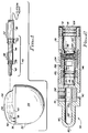
- Fig. 1 there is shown a diagram of the main elements of a pacemaker system, including a pacemaker 30 and a pacemaker lead 32.
- the pacemaker 30 includes a hermetically sealed housing or (as it is more frequently referred to as) pacemaker "can" 34, inside of which the pacemaker electronic circuits and battery are housed. Electrical contact between the electronic circuits and the pacemaker lead is made with by means of one or more feedthrough terminals 36, 38.
- the pacemaker can 34 is made from an electrically conductive material, and electrical contact may also be made through an exposed (noninsulated) portion of the conductive material of the pacemaker can 34.
- Fig. 1 illustrates a proximal end 40 of a bipolar pacemaker lead 32 made in accordance with the VS-1 standard.
- This side profile of the proximal end 40 includes a proximal tip electrode 42 and a proximal ring electrode 44.
- Adjacent to the tip electrode 42 is a first set of sealing rings 46, followed by a smooth portion 48.
- Adjacent to the ring electrode 44 is a second set of sealing rings 50, followed by a smooth portion 52.
- the tip electrode 42 and the ring electrode 44 make respective electrical contact with the feedthrough terminals 36, 38 of the pacemaker 30 by way of a pacemaker connector 54.
- the outline of pacemaker connector 54 is shown in Fig. 1 as a dotted line within a pacemaker header assembly 56.
- the pacemaker connector 54 is formed within the header assembly 56 so as to receive the proximal end 40 of the pacemaker lead 32.
- the header assembly 56 is fastened to the top of the pacemaker can 34.
- a first conductor 58 and a second conductor 60 are included in the header assembly 56 for making electrical contact between appropriate terminals of the pacemaker connector 54 and the feedthrough terminals 36, 38.
- the proximal end 40 functioning as a "male” connector
- slides inside of the pacemaker connector 54 functioning as a "female” connector. It is the function of the pacemaker connector 54 to allow a reliable, yet detachable, electrical contact to be maintained between the tip and ring electrodes 42, 44 and the respective feedthrough terminals 36, 38.
- pacemaker connector 54 invention described herein is described in terms of a bipolar connection. That is, the invention is described with reference to the use of a bipolar pacemaker lead, i.e., a pacemaker lead having two separate conductors, one connected to a proximal tip electrode and the other connected to a proximal ring electrode.
- a bipolar pacemaker lead i.e., a pacemaker lead having two separate conductors, one connected to a proximal tip electrode and the other connected to a proximal ring electrode.
- various aspects of the invention also have applicability to unipolar pacing (single conductor leads), or multi-polar pacing (multiple conductor leads).
- a cross-sectional view of a preferred embodiment of a multi-part molded pacemaker connector made in accordance with the present invention is designated generally by the reference numeral 54.
- the individual components of the pacemaker connector 54 are best seen in the exploded view of the pacemaker connector shown in Fig. 3.
- many of the details associated with these components, as well as their manner of assembly, can also be ascertained from the other figures.
- the same numerals will be used to describe the same parts throughout.
- the components of the pacemaker connector 54 include a body tip 62, a first inner seal 64, a body ring 66, a garter spring contact 68, an entrance connector 70, and a second inner seal 72.
- the body tip 62, body ring 66 and the entrance connector 70 are molded parts which readily allow the insertion of the inner seals 64, 72 and the garter spring contact 68 prior to them being joined together, thereby facilitating their manufacturability.
- the body ring 66 and entrance connector 70 have a main channel or opening through which the proximal end 40 of the pacemaker lead 32 passes or enters when inserted into the pacemaker connector 54.
- the body tip 62 also has a main channel or opening into which the proximal end 40 of the pacemaker lead 32 resides when it is inserted into the pacemaker connector 54.
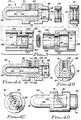
- FIG. 4A shows a cross-sectional profile view of the body tip 62, including a conductor block 74 molded therein.
- Fig. 4B shows a cross-sectional view of the body tip 62 across the lines B-B.
- Fig. 4C shows a view of the body tip 62 from an open end 78.
- Fig. 4D shows a top view of the body tip 62 and the conductor block 74.
- Fig. 4E shows just the polymer tip portion 76 of the body tip 76 without the conductor block 74.
- the body tip 62 includes a tubular shaped, polymer tip portion 76.
- the polymer tip portion 76 has an open end 78 and a closed end 80.
- the closed end 80 provides a channel 82 where a portion of the tip electrode 42 of the pacemaker lead 32 may reside.
- a recess 84 at the open end 78 of the polymer tip portion 76 provides a smooth inner surface against which the sealing rings 46 (Fig. 1) of the proximal end 40 of the pacemaker lead 32 may act to form a fluid-tight seal.
- a narrow neck 86 defines a diameter that is just large enough for the tip electrode 42 to pass therethrough, but sufficiently small to prevent the sealing rings 46 (Fig. 1) from passing therethrough.
- a cavity 88 in the polymer tip portion 76 identifies the location where the conductor block 74 is "insert molded" therein. Insert molding is simply the process in which components are inserted into a mold and cured together with the injected polymer.
- the polymer used is polysulfone.
- a window 90 is molded therein to expose a portion of the conductor block 74 for the attachment of the first conductor 58 (Fig. 1).
- the window 90 exposes two sides 92 and 93 (Fig. 4B) of the conductor block 74 to facilitate a convenient attachment of the first conductor 58 from two different possible positions 95, 96 as shown in Fig. 4F.
- a circumferential protruding shoulder 98 provides a surface or stub that is press-fittably inserted into the body ring 66 when the body ring 66 is joined to the body tip 62.
- the front edge of the shoulder 98 is angled (e.g., chamfered at 15 degrees), the reason for which will be described below in conjunction with the description of the body ring 66.
- a conductor block 74 is molded into the body tip 62 so as to form an integral part thereof.
- the connector block is a square conductive piece which has a hole or channel 100 drilled therethrough. The tip electrode 42 is received in the channel 100 when the proximal end 40 of the pacemaker lead 32 is inserted into the pacemaker connector 54. Another hole or channel 102, transverse to the channel 100, is threaded so as to receive a set screw 104.
- the set screw 104 may be urged along the movement axis 106 in a conventional manner in order to firmly secure the tip electrode 42 to the conductor block 74 and to secure the pacemaker lead 32 in place axially.
- the set screw 104 has a flat end 105 to prevent damage to the lead 32 when the set screw 104 is urged along the movement axis 106.
- the conductor block 74 is preferably made from a conductive material compatible with body fluids such as 316L stainless steel. In the present invention, the conductor block 74 is precisely seated in the appropriate mold cavity for the body tip 62. The injection molding process is then carried out in conventional manner. As the polysulfone (or other equivalent material) cures, the connector block 74 is permanently held in its prescribed position within the body tip 62.
- a set-screwless connection scheme may be employed using two garter spring contacts, one for contacting the tip electrode 42, the other for contacting the ring electrode 44.
- an additional axial retention means for the pacemaker lead 32 is required to prevent possible disconnection.
- the entrance connector 70 is a tubular molded part having an open front end 108 and an open rearward end 110. At the front end 108 of the entrance connector 70 is a first recess 112. This recess 112 is dovetailed, as shown at 114. This first dovetailed recess 112 is designed to receive the second inner seal 72 (Fig. 3). The recess 112 holds the second inner seal 72 captive in such a way that it cannot be dislodged by insertion or extraction of a lead.
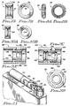
- the second inner seal 72 which is sometimes referred to as an entrance seal, is shaped like a ring or doughnut, as shown in Figs. 7A and 7B.
- the second inner seal 72 is shown to have inner circumferential ridges 116 adapted to make sealing contact with the smooth surface 52 (Fig. 1) of the pacemaker lead 32.
- the second inner seal 72 also has outer circumferential ridges 118 adapted to make sealing contact with the smooth inner diameter of the recess 112.
- the entrance connector 70 has a second recess 120.
- This second recess 120 is adjacent to the dovetailed recess 112, having a smaller diameter than the recess 112. It is the function of the second recess 120 to provide a smooth surface against which the sealing rings 50 (Fig. 1) of the pacemaker lead 32 may make sealing contact. (Note from the cross-sectional view of Fig. 6A that the recesses have the appearance of counterbores having differing diameters.
- counterbore could imply that the counterbore is machined into the particular part wherein the counterbore is found, and whereas the recesses and are not machined, but are formed during the molding process of the body tip 62, the term “counterbore” is not used herein.
- a conductive tube 124 has a flanged portion 126 at one end for retention purposes.
- the flanged portion 126 of the conductive tube 124 is "insert molded" into the rearward end 110 of the entrance connector 70 so as to make it an integral part thereof.
- a non-flanged portion 128 of the conductive tube 124 extends outwardly from the rearward end 110 of the entrance connector 70.
- the conductive tube 124 is preferably made of 316L stainless steel. As the polysulfone (or other equivalent material) cures, the conductive tube 124 is permanently held in its prescribed position within the entrance connector 70.
- FIG. 6C an entrance connector subassembly 130 is shown.
- the entrance connector subassembly 130 includes the garter spring contact 68 (Fig. 3). (Cross-sectional views of the garter spring contact 68 are also shown in Figs. 8A and 8B.)
- the garter spring contact 68 is inserted into the conductive tube 124 so that it makes circumferential contact with the inner surface of the conductive tube 124 and rests against a shoulder 134 (Fig. 6A) in the entrance connector 70.
- a suitable garter spring contact 68 may be obtained commercially from Bal Seal Engineering Company, Inc., of Santa Ana, California, and is also known as a "canted coil” spring, or a "canted coil garter spring contact”.
- the dimensions of the garter spring contact 68 are such that its inner diameter protrudes into the channel formed by the conductive tube 124.
- the inner diameter of the garter spring contact 68 is a slightly smaller diameter than the outer diameter of the ring electrode 44.
- the ring electrode 44 compresses the garter spring contact 68 somewhat in order to expand its diameter to allow the ring electrode 44 to fit therein. This compression advantageously assures that the garter spring contact 68 surrounds and makes good multi-point electrical contact around the entire circumference of the ring electrode 44.
- the entrance connector subassembly 130 shown in Fig. 6C includes the molded entrance connector 70, the conductive tube 124, the garter spring contact 68 and the second inner seal 72.
- the body ring 66 is a tubular molded part which has an open front open 140 and an open rearward end 142. At the rearward end 142 of the body ring 66, there is a recess 144.
- the recess 144 is dimensioned so as to provide a leak-proof fit when the body tip 62 and the body ring 66 are joined, with the shoulder 98 (Fig. 4A) of the body tip 62 tightly fitting within the recess 144 of the body ring 66.
- the recess 144 when mated with the shoulder 98, forms a dovetail recess for receiving the first inner seal 64 (Fig. 3).
- the recess 144 holds the first inner seal 64 captive in such a way that it cannot be dislodged by insertion or extraction of a lead.
- a recess 146 adjacent to the recess 144, defines a diameter that is just large enough for the ring electrode 44 to pass therethrough.
- the recess 146 also forms a shoulder 148 and a channel 150.
- the shoulder 148 is used to prevent lateral movement of the garter spring contact 68 in a rearward direction when the body ring 66 is joined with the entrance connector subassembly 130.
- the channel 150 is used to receive the conductive tube 124 which is molded in the entrance connector 70.
- the recess 146 is also adjacent to a larger recess 152 at the front end 140 of the body ring 66.
- Recess 152 is dimensioned so as to provide a leak-proof fit when the body ring 66 and the entrance connector 70 are joined, with the shoulder 148 of the body ring 66 tightly fitting against the conductive tube 124 of the entrance connector 70.
- the body ring subassembly 164 including the body ring 66 and the first inner seal 64, is shown in Fig. 9C.
- the first inner seal 64 has one or two inwardly protruding sealing rings 154 adapted to make sealing contact with the smooth surface 48 of the pacemaker lead 32 when the proximal end 40 of the pacemaker lead 32 is inserted into the pacemaker connector 54.
- the first inner seal 64 is inserted into the body ring 66 prior to joining the body ring 66 to the body tip 62, thereby facilitating assembly of the pacemaker connector 54.
- the molded body ring 66 includes a first and second window 156, 158 therethrough to provide access to the conductive tube 124.
- two windows are used to facilitate a convenient attachment of the second conductor 60 from two different possible contact points 160, 162 on the conductive tube 124.
- the access windows chosen are located on one side of the pacemaker connector 54.
- the access windows for the body tip 62 and body ring 66 may be any point which is convenient for attaching the conductors without departing from the spirit of the invention.
- the pacemaker connector 54 can be pretested for leakage, dimensionality, conductivity, as well as for any other specified parameters, such as proper lead insertion/removal forces. This ability to pretest the pacemaker connector 54 significantly improves the yield of the overall pacemaker manufacturing process. Further, the multi-part nature of the pacemaker connector allows the pacemaker connector to be inexpensively manufactured or reworked, if required.
- the first and second conductors 58, 60 (Fig. 1) are attached to the pacemaker connector 54.
- the first conductor 58 is attached to the conductor block 74 through the access windows 90 on either side 92 or 93 (Fig. 4F) of the conductor block 74.
- the second conductor 60 is attached to the conductive tube 124 through either one of the access windows 156 or 158 (Fig. 9B) in the body ring 66.
- electrical contact is made by welding or otherwise attaching a preformed conductor ribbon set 166, as shown in Fig. 11.
- the ribbon conductor set 166 is formed by chemical etching and/or forming a thin sheet of conductive material to define a plurality of conductor ribbons supported within a frame (not shown).
- the ribbon conductor set 166 and frame are shaped in a predetermined precise array to extend between the conductor blocks and the feedthrough terminals 36, 38. After welding, the frame is removed.
- the pacemaker connector 54 is then properly positioned above the pacemaker can 34 (using an appropriate header assembly mold or fixture guide), and the conductor ribbon set 166 is positioned appropriately so as to make electrical contact with the feedthrough terminals 36, 38. In so doing, care must be exercised to make sure the conductor ribbons 166 do not touch each other. Preferably, the ends of the conductor ribbons 166 are welded, or otherwise permanently bonded, to the feedthrough terminals 36, 38.
- the pacemaker header assembly 56 (Fig. 1) is completed by casting the pacemaker connector 54 in a biocompatible epoxy, such as Hysol, which epoxy also serves to bond the connector top to the pacemaker can 34.
- the inner seals 64, 72 are preferably made from a flexible silicon elastomer, having a 70A shore hardness.
- the conductor ribbon set 166 is preferably made from 316L stainless steel.
- the garter spring contact 68 is made from a suitable corrosion-resistant conductive spring material, such as MP35N alloy.
- the dimensions for the pacemaker connector 54 are dictated by the particular connector standard, or other connector specification, that is used.
- the VS-1 dimensions for example, are published in the known literature.
- a method of making a molded pacemaker connector 54 in accordance with the present invention is illustrated.
- the reference numerals in parenthesis are the same as are used in the description of Figs. 1-11 above.
- the method includes the steps of making three molded pacemaker connector subassemblies (i.e., a ring connector, a tip connector and an entrance connector) and joining them together.
- the method steps for making the ring connector subassembly include a first step, at block 178, of injecting a nonconductive polymer into a ring connector mold while the polymer is in a liquid state.
- the cured polymer is removed from the pacemaker connector mold to yield the molded body ring (66).
- a first inner seal (64) is inserted within the body ring (66) to yield the body ring subassembly (164).
- the method steps for making the tip connector include inserting a connector block (74) into a tip connector mold at block 186. Thereafter, a nonconductive polymer is injected into the tip connector mold while the polymer is in a liquid state at block 188. The polymer is then allowed to cure to assume a solid state at block 190, after which the cured polymer, including the connector block (74), is removed from the tip connector mold at block 192.
- the cured polymer and the connector block (74) molded therein thus comprise the molded body tip 62 of the molded pacemaker connector 54.
- the method steps for making the entrance connector subassembly (130) include inserting a conductive tube (124) into the entrance connector mold at block 197. Injecting a nonconductive polymer into the entrance connector mold while the polymer is in a liquid state at block 198. A next step, block 200, allows the polymer to cure to assume a solid state. Then, at block 202, the cured polymer, including the conductive tube (124), is removed from the entrance connector mold to yield the molded entrance connector (70). Next, a second seal is inserted within the molded entrance connector (70) at block 204. At block 205, a garter spring contact (68) is inserted into the molded entrance connector (70) so as to make physical contact with an inner surface of the conductive tube (124). The garter spring contact (68) thus provides a means for making electrical contact between the conductive tube (124) and the outer circumference of the ring electrode (44) of the pacemaker lead 32 inserted into the pacemaker connector 54 so as to pass through the garter spring contact 60.
- the method of making the molded pacemaker connector 54 next involves joining the molded body tip 62 to the body ring subassembly (164), including the first seal (64), to produce a tip/ring subassembly at block 196.
- the method next involves joining the entrance connector subassembly (130), including the second seal (72), the garter spring contact (68) and the conductive tube (124) to the already joined tip/ring subassembly at block 206 to yield the pacemaker connector 54.
- the pacemaker connector 54 is tested for leakage conductivity and dimensionality at block 208. If such tests are passed successfully, then the method includes connecting ribbon conductors (174) to respective terminals of a sealed pacemaker at block 210. As a final step, block 212, the method involves casting the tested molded pacemaker connector 54 in an epoxy header assembly header 56 onto the sealed pacemaker case 30.
- the present invention provides a pacemaker connector, and method of making a pacemaker connector, that readily meets the stringent VS-1 standard (or any other standard that may be imposed), and yet is easy and inexpensive to manufacture and assemble, avoiding the necessity of machining individual parts in order to obtain precision dimensions.
- the pacemaker connector thus provided may be used with pacemaker leads having seals (VS-1B) or with pacemakers not having seals. Further, once assembled, the pacemaker connector can be pretested for leakage, conductivity and dimensionality prior to being cast into a pacemaker header assembly, thereby significantly improving the overall yield of the pacemaker assembly process.
- the pacemaker connector herein described can be manufactured and assembled is due is large part to the fact that it is made from a plurality of individually molded precision parts. Each individual part advantageously is designed to readily allow the insertion of seals, garter spring contacts, and other connector components, prior to joining the parts together., As also described above, it is seen that the present invention provides a pacemaker connector utilizing a "garter spring contact" to make electrical contact around the entire periphery of a proximal electrode of a pacemaker lead. Such contact assures that a reliable electrical connection will be made and maintained, yet such contact (unlike a set screw) will not damage the proximal electrode.
- such contact does not require any adjustments (as does a set screw), as the gripping force of the garter spring contact is controlled by the size of the garter spring contact and the dimension (diameter) of the recess within which the garter spring contact resides.
Landscapes
- Health & Medical Sciences (AREA)
- Engineering & Computer Science (AREA)
- Biomedical Technology (AREA)
- Nuclear Medicine, Radiotherapy & Molecular Imaging (AREA)
- Radiology & Medical Imaging (AREA)
- Life Sciences & Earth Sciences (AREA)
- Animal Behavior & Ethology (AREA)
- General Health & Medical Sciences (AREA)
- Public Health (AREA)
- Veterinary Medicine (AREA)
- Manufacturing & Machinery (AREA)
- Electrotherapy Devices (AREA)
Abstract
Claims (21)
- Connecteur de stimulateur cardiaque à plusieurs parties destiné à recevoir une extrémité (40) proximale d'un conducteur (32) de stimulateur cardiaque, le conducteur de stimulateur cardiaque ayant des première et seconde électrodes (42,44) à distance l'une de l'autre, le connecteur comprenant : une pointe (62) de corps ayant un évidement destiné à recevoir l'extrémité (40) proximale du conducteur (32) de stimulateur cardiaque en son sein; un contact (68) à ressort cylindrique en anneau conducteur de l'électricité; un connecteur (70) d'entrée comportant un canal qui le traverse destiné à recevoir l'extrémité proximale du conducteur de stimulateur cardiaque en son sein, le connecteur d'entrée comportant un tube (124) conducteur, qui forme un évidement destiné à recevoir le contact à ressort cylindrique en anneau; et une bague (66) de corps ayant un canal qui la traverse destiné à recevoir l'extrémité proximale du conducteur de stimulateur cardiaque en son sein; les première (42) et seconde (44) électrodes proximales à distance l'une de l'autre d'un conducteur de stimulateur cardiaque pouvant ainsi être insérées dans le connecteur (54) de stimulateur cardiaque et entrer en contact électrique respectif avec l'électrode (74) de bloc et le contact (68) à ressort cylindrique en anneau; caractérisé en ce que la pointe (62) de corps, le connecteur (70) d'entrée et la bague (66) de corps sont en une construction moulée et le tube (124) conducteur est moulé par insertion de manière à former une partie d'une pièce avec le connecteur (70) d'entrée; la pointe de corps comporte un bloc (74) connecteur, le bloc (74) connecteur étant moulé par insertion de manière à former une partie d'une pièce de la pointe, le bloc connecteur ayant un canal (100) qui le traverse, la pointe de corps moulé ayant en outre une première fenêtre (90) d'accès qui la traverse pour permettre d'établir un contact électrique avec le bloc de connecteur; le ressort cylindrique en anneau ayant une dimension telle qu'il peut y avoir un contact circonférentiel avec la surface intérieure du tube conducteur; la bague de corps a une rainure (150) destinée à recevoir le tube conducteur de manière ajustée serrée, la bague de corps comportant en outre une seconde fenêtre (156,158) d'accès qui la traverse pour permettre d'établir un contact électrique avec le tube conducteur; et des premiers moyens (98,144) de jonction réalisent la jonction entre la pointe de corps moulé et la bague de corps moulé tandis que des seconds moyens (124,146,152) de jonction réalisent la jonction entre le connecteur d'entrée et la bague de corps; un contact électrique pouvant ainsi être réalisé entre les première et seconde électrodes proximales du conducteur de stimulateur cardiaque par l'intermédiaire respectivement des première et seconde fenêtres d'accès.
- Connecteur suivant la revendication 1, caractérisé par un joint (64) d'étanchéité intérieur annulaire inséré dans la bague (66) de corps moulé; et par un joint (72) d'étanchéité d'entrée annulaire inséré dans le connecteur (70) d'entrée; dans lequel les joints intérieur et d'entrée ont des nervures (154,116) annulaires destinées à réaliser un contact pouvant être étanchéifié avec une extrémité (40) proximale du conducteur (32) de stimulateur cardiaque lorsque les première et seconde électrodes (40,44) proximale du conducteur de stimulateur cardiaque sont insérées dans le connecteur (54) de stimulateur cardiaque.
- Connecteur suivant la revendication 1 ou la revendication 2, caractérisé en ce que les premiers moyens de jonction comprennent : des premiers moyens (98,144) d'accouplement sur l'un parmi la pointe (62) de corps et la bague (66) de corps pour réaliser un accouplement par ajustage serré avec l'autre parmi la pointe de corps et la bague de corps.
- Connecteur suivant la revendication 3, caractérisé en ce que les premiers moyens d'accouplement comportent : une lèvre (98) annulaire faisant saillie de la pointe (62) de corps moulé dont la taille est appropriée pour un ajustage serré à l'intérieur de la bague (106) de corps moulé.
- Connecteur suivant l'une quelconque des revendications précédentes, caractérisé en ce que les seconds moyens de jonction comportent : des seconds moyens (124,148, 152) d'accouplement sur l'un parmi la bague (70) de corps et le connecteur (70) d'entrée pour un accouplement par ajustage serré avec l'autre parmi la bague de corps et le connecteur d'entrée.
- Connecteur suivant la revendication 5, caractérisé en ce que les seconds moyens d'accouplement comportent un évidement (152) dans la bague (66) de corps moulé dont la dimension est appropriée pour un ajustage serré avec le tube (124) conducteur.
- Connecteur suivant l'une quelconque des revendications précédentes, caractérisé en ce que la pointe (62) de corps moulé, le corps (66) moulé et le connecteur (70) d'entrée moulé sont moulés à partir de polysulfone.
- Connecteur suivant l'une des revendications précédentes, caractérisé en ce que les première et seconde électrodes (42,44) à distance l'une de l'autre de l'extrémité (40) proximale du conducteur (32) de stimulateur cardiaque sont disposées de manière à être connectées électriquement aux première et seconde bornes (36,38) d'un stimulateur (30) cardiaque implantable, en ce que le connecteur (70) d'entrée, la bague (66) de corps et la pointe (62) de corps sont non conducteurs, en ce que le contact (68) de ressort cylindrique à anneau comporte un matériau conducteur électriquement; et en ce que des moyens (166) sont prévus pour réaliser un contact électrique respectif du bloc (74) connecteur et du tube (124) conducteur vers les première et seconde bornes de stimulateur cardiaque au moyen des première et seconde fenêtres (90,156,158) d'accès respectivement.
- Connecteur suivant la revendication 8, caractérisé en ce que les moyens destinés à réaliser un contact électrique du bloc (74) connecteur et du tube (124) conducteur aux première et seconde bornes (36, 38) du stimulateur cardiaque comportent des premier et second conducteurs (176) à ruban.
- Connecteur suivant l'une quelconque des revendications précédentes, caractérisé en ce que la pointe (62) de corps, le connecteur (70) d'entrée, la bague (66) de corps, le bloc (74) connecteur, le contact (68) de ressort cylindrique en anneau et le tube (124) conducteur sont logés dans des moyens en un matériau biocompatible dans une partie de tête (56) d'un stimulateur cardiaque.
- Connecteur suivant la revendication 10, caractérisé en ce que les moyens de logement comportent un boîtier en époxy.
- Connecteur suivant l'une quelconque des revendications 2 à 11, caractérisé en ce que la bague (66) de corps comporte un évidement (144) à une extrémité de la bague de corps, le joint (64) d'étanchéité intérieur annulaire étant insérable dans cet évidement pour le rendre étanche contre les fuites corporelles.
- Connecteur suivant l'une quelconque des revendications 2 à 12, caractérisé en ce que le connecteur (70) d'entrée comporte un évidement (112) à l'une des extrémités, le joint (72) d'étanchéité d'entrée annulaire étant adapté pour réaliser une étanchéité contre les fluides corporels.
- Procédé de fabrication d'un connecteur de stimulateur cardiaque moulé à l'intérieur d'un boîtier étanche qui est traversé par une première borne de traversée d'alimentation, le procédé comprenant les étapes qui consistent à : réaliser une pointe (62) de corps non conductrice, la pointe de corps comportant une cavité en son sein pour recevoir une électrode (42) de pointe proximale d'un conducteur (32) de stimulateur cardiaque; à réaliser une bague (66) de corps non conductrice et la bague de corps comportant un canal pour y faire passer l'extrémité (40) proximale du conducteur implantable; à réaliser un connecteur (70) d'entrée non conducteur, le connecteur d'entrée comprenant un canal destiné à y faire passer l'extrémité (40) proximale du conducteur implantable; et à joindre la pointe de corps, la bague de corps et le connecteur d'entrée ensemble, caractérisé par l'étape qui consiste à former la pointe (62) de corps, la bague (66) de corps et le connecteur (70) d'entrée en moulant la pointe de corps qui comporte en outre un bloc (74) connecteur conducteur afin de réaliser un contact électrique avec l'électrode de pointe proximale du conducteur implantable; à insérer une première bague (64) d'étanchéité dans un premier évidement (144) dans la bague de corps et à insérer une seconde bague (70) d'étanchéité dans un second évidement (112) dans le connecteur d'entrée; à connecter un premier conducteur (166) à une extrémité de la première borne (38) de traversée d'alimentation et à l'autre extrémité à un bloc connecteur conducteur, le bloc connecteur, la bague de corps et le connecteur d'entrée, qui contient le connecteur moulant le sous-assemblage connecteur; et à mouler le sous-assemblage connecteur en un matériau compatible avec le corps sur le boîtier.
- Procédé suivant la revendication 14, caractérisé en ce que les étapes qui consistent à réaliser la pointe (62) de corps comportent les étapes qui consistent à : insérer le bloc (74) connecteur conducteur dans un moule de pointe de corps; à injecter un polymère non conducteur dans le moule de pointe de corps, tandis que le polymère est à l'état liquide, et à permettre au polymère de durcir pour prendre un état solide; et à retirer le premier polymère durci comportant le bloc connecteur du moule de pointe de corps.
- Procédé suivant la revendication 14 ou 15, caractérisé en ce que l'étape qui consiste à réaliser une bague (66) de corps comporte les étapes qui consistent à : injecter un polymère conducteur dans un moule de bague de corps tandis que le polymère est à l'état liquide et permettre au polymère de durcir pour prendre un état solide et retirer le second polymère durci du moule de bague de corps.
- Procédé suivant l'une quelconque des revendications 14 à 16, dans lequel le connecteur d'entrée comporte un tube (124) conducteur destiné à réaliser un contact électrique avec une électrode (44) de bague proximale du conducteur (32) implantable, caractérisé en ce que l'étape qui consiste à réaliser un connecteur (70) d'entrée comporte les étapes qui consistent à : insérer le tube (124) conducteur dans un moule de connecteur d'entrée; injecter un polymère non conducteur dans le moule de connecteur d'entrée tandis que le polymère est à l'état liquide, et permettre au polymère de durcir pour prendre un état solide; et retirer le troisième polymère durci, comprenant le tube conducteur, du moule connecteur d'entrée.
- Procédé suivant la revendication 17, caractérisé en ce que l'étape qui consiste à réaliser un connecteur (70) d'entrée comporte en outre les étapes qui consistent à : insérer un contact (68) à ressort cylindrique à anneau conducteur à l'intérieur d'une surface intérieure du tube (124) conducteur, le contact (68) à ressort cylindrique à anneau permettant ainsi un contact électrique entre le tube conducteur et le conducteur de circonférence extérieur lorsqu'il est inséré dans le sous-assemblage connecteur.
- Procédé suivant la revendication 17 ou 18, dans lequel le boîtier a une seconde borne (36) de traversée d'alimentation qui le traverse, caractérisé en ce que l'étape qui consiste à réaliser un connecteur (70) d'entrée comporte en outre l'étape qui consiste à connecter un second conducteur (166) à une extrémité à la seconde borne (36) de traversée d'alimentation et à son autre extrémité au tube (124) conducteur.
- Procédé suivant l'une quelconque des revendications 14 à 19, caractérisé par l'étape supplémentaire qui consiste à : former une fenêtre (90,156, 158) d'accès dans au moins deux parmi la pointe (62) de corps, la bague (66) de corps et le connecteur (70) d'entrée de manière que les premier et second conducteurs (166) puissent être connectés par son intermédiaire.
- Procédé suivant l'une quelconque des revendications 14 à 20, caractérisé en ce que l'étape qui consiste à réaliser une première et une seconde bagues (64, 72) d'étanchéité comporte l'étape qui consiste à : réaliser une première et seconde bagues annulaires respectivement à partir d'un élastomère de silicium souple, chaque bague annulaire ayant une pluralité de nervures (154,116) circonférentielles adaptées pour réaliser un contact d'étanchéité avec la circonférence de l'extrémité (40) proximale du conducteur (32) implantable lorsqu'il est inséré dans le sous-assemblage connecteur.
Applications Claiming Priority (5)
| Application Number | Priority Date | Filing Date | Title |
|---|---|---|---|
| US518618 | 1990-05-03 | ||
| US07/518,618 US5012807A (en) | 1990-05-03 | 1990-05-03 | Multi-part molded pacemaker connector and method of making same |
| US649386 | 1991-01-30 | ||
| US07/649,386 US5076270A (en) | 1990-05-03 | 1991-01-30 | Apparatus and method for making electrical connections in an implantable pacemaker |
| PCT/US1991/003070 WO1991016947A1 (fr) | 1990-05-03 | 1991-05-03 | Connecteur de stimulateur cardiaque moule a parties multiples, procede de fabrication et ensemble matriciel de stimulateur cardiaque |
Publications (3)
| Publication Number | Publication Date |
|---|---|
| EP0484483A1 EP0484483A1 (fr) | 1992-05-13 |
| EP0484483A4 EP0484483A4 (en) | 1992-09-30 |
| EP0484483B1 true EP0484483B1 (fr) | 1996-07-24 |
Family
ID=27059536
Family Applications (1)
| Application Number | Title | Priority Date | Filing Date |
|---|---|---|---|
| EP91909089A Expired - Lifetime EP0484483B1 (fr) | 1990-05-03 | 1991-05-03 | Connecteur de stimulateur cardiaque moule a parties multiples, procede de fabrication et ensemble matriciel de stimulateur cardiaque |
Country Status (5)
| Country | Link |
|---|---|
| US (1) | US5076270A (fr) |
| EP (1) | EP0484483B1 (fr) |
| AU (1) | AU650018B2 (fr) |
| DE (1) | DE69121052T2 (fr) |
| WO (1) | WO1991016947A1 (fr) |
Cited By (1)
| Publication number | Priority date | Publication date | Assignee | Title |
|---|---|---|---|---|
| US7083474B1 (en) | 2004-12-08 | 2006-08-01 | Pacesetter, Inc. | System for lead retention and sealing of an implantable medical device |
Families Citing this family (84)
| Publication number | Priority date | Publication date | Assignee | Title |
|---|---|---|---|---|
| US5267564A (en) * | 1991-06-14 | 1993-12-07 | Siemens Pacesetter, Inc. | Pacemaker lead for sensing a physiologic parameter of the body |
| US5324311A (en) * | 1992-09-04 | 1994-06-28 | Siemens Pacesetter, Inc. | Coaxial bipolar connector assembly for implantable medical device |
| US5489225A (en) * | 1993-12-16 | 1996-02-06 | Ventritex, Inc. | Electrical terminal with a collet grip for a defibrillator |
| US5620477A (en) * | 1994-03-31 | 1997-04-15 | Ventritex, Inc. | Pulse generator with case that can be active or inactive |
| US5556421A (en) * | 1995-02-22 | 1996-09-17 | Intermedics, Inc. | Implantable medical device with enclosed physiological parameter sensors or telemetry link |
| US5817984A (en) * | 1995-07-28 | 1998-10-06 | Medtronic Inc | Implantable medical device wtih multi-pin feedthrough |
| DE19622669A1 (de) * | 1996-06-05 | 1997-12-11 | Implex Gmbh | Implantierbare Einheit |
| US5935465A (en) | 1996-11-05 | 1999-08-10 | Intermedics Inc. | Method of making implantable lead including laser wire stripping |
| US5843141A (en) * | 1997-04-25 | 1998-12-01 | Medronic, Inc. | Medical lead connector system |
| US5871513A (en) * | 1997-04-30 | 1999-02-16 | Medtronic Inc. | Centerless ground feedthrough pin for an electrical power source in an implantable medical device |
| US6643550B2 (en) * | 2000-12-15 | 2003-11-04 | Cardiac Pacemakers, Inc. | Multi-polar connector |
| US6912423B2 (en) * | 2000-12-15 | 2005-06-28 | Cardiac Pacemakers, Inc. | Terminal connector assembly for a medical device and method therefor |
| SE0004764D0 (sv) * | 2000-12-20 | 2000-12-20 | St Jude Medical | An electrode terminal fixation appliance |
| US6854994B2 (en) * | 2001-04-19 | 2005-02-15 | Medtronic, Inc. | Medical electrical lead connector arrangement including anti-rotation means |
| US6755694B2 (en) | 2001-04-19 | 2004-06-29 | Medtronic, Inc. | Lead upsizing sleeve |
| US6921295B2 (en) * | 2001-04-19 | 2005-07-26 | Medtronic, Inc. | Medical lead extension and connection system |
| US6792312B2 (en) | 2001-09-06 | 2004-09-14 | Medtronic, Inc. | Connector module having internal weld plates |
| US6895276B2 (en) * | 2002-02-28 | 2005-05-17 | Medtronic, Inc. | In-line lead header for an implantable medical device |
| US6862478B1 (en) | 2002-06-14 | 2005-03-01 | Pacesetter, Inc. | Connector top for implantable medical device |
| CA2448376A1 (fr) * | 2002-11-05 | 2004-05-05 | Wilson Greatbatch Technologies, Inc. | Barrette de contact monobloc pour dispositif medical implantable |
| US7647111B2 (en) * | 2003-07-31 | 2010-01-12 | Medtronic, Inc. | Connector assembly for connecting a lead and an implantable medical device |
| US7299095B1 (en) * | 2003-12-17 | 2007-11-20 | Pacesetter, Inc. | Electrical contact assembly |
| US7070455B2 (en) * | 2004-02-23 | 2006-07-04 | Bal Seal Engineering Co., Inc. | Stackable assembly for direct connection between a pulse generator and a human body |
| EP1794848A4 (fr) * | 2004-08-27 | 2010-11-24 | Pmi Ind Inc | Connecteur souple pour cablage electrique implantable |
| WO2006044539A2 (fr) * | 2004-10-18 | 2006-04-27 | Bal Seal Engineering Co., Inc. | Contacts ressort en tire-bouchon pour dispositif medicaux implantables |
| US7316593B2 (en) * | 2005-05-19 | 2008-01-08 | Bal Seal Engineering Co., Inc. | Electrical connector with embedded canted coil spring |
| US7429199B2 (en) * | 2005-08-12 | 2008-09-30 | Burgess James P | Low resistance, low insertion force electrical connector |
| ATE510590T1 (de) * | 2005-09-29 | 2011-06-15 | St Jude Medical | Implantierbare medizinische vorrichtung mit verschweissbaren housing und header |
| US9168383B2 (en) | 2005-10-14 | 2015-10-27 | Pacesetter, Inc. | Leadless cardiac pacemaker with conducted communication |
| US8010209B2 (en) | 2005-10-14 | 2011-08-30 | Nanostim, Inc. | Delivery system for implantable biostimulator |
| DE102006003223A1 (de) * | 2005-12-08 | 2007-06-14 | Biotronik Crm Patent Ag | Gehäuse für ein medizinisches Implantat |
| EP1795224A1 (fr) * | 2005-12-12 | 2007-06-13 | Greatbatch, Inc. | Connecteur électrique pour dispositif médical implantable |
| US7546165B2 (en) | 2005-12-19 | 2009-06-09 | Cardiac Pacemakers, Inc. | Interconnections of implantable lead conductors and electrodes and reinforcement therefor |
| US7654843B2 (en) * | 2006-02-28 | 2010-02-02 | Medtronic, Inc. | Connector assembly with internal seals and manufacturing method |
| US20080046059A1 (en) * | 2006-08-04 | 2008-02-21 | Zarembo Paul E | Lead including a heat fused or formed lead body |
| US7917229B2 (en) | 2006-08-31 | 2011-03-29 | Cardiac Pacemakers, Inc. | Lead assembly including a polymer interconnect and methods related thereto |
| US7717754B2 (en) * | 2006-12-07 | 2010-05-18 | Medtronic, Inc. | Connector assembly with internal seals and manufacturing method |
| US8091226B2 (en) * | 2007-04-11 | 2012-01-10 | Bal Seal Engineering, Inc. | Integrated header connector system |
| US8123567B2 (en) * | 2007-10-02 | 2012-02-28 | Medtronic, Inc. | Connector assemblies and contacts for implantable medical electrical systems |
| WO2009045772A1 (fr) * | 2007-10-03 | 2009-04-09 | Medtronic, Inc. | Ensembles de connecteurs pour des systèmes électriques médicaux implantables |
| US8108045B2 (en) * | 2007-10-29 | 2012-01-31 | Cretex Orthopaedics, Inc. | Set screw-less pacemaker header with lead lock system |
| US8219209B2 (en) | 2008-08-15 | 2012-07-10 | Cardiac Pacemakers, Inc. | Implantable medical lead having reduced dimension tubing transition |
| US8527068B2 (en) | 2009-02-02 | 2013-09-03 | Nanostim, Inc. | Leadless cardiac pacemaker with secondary fixation capability |
| US8366475B2 (en) * | 2009-06-05 | 2013-02-05 | Bal Seal Engineering, Inc. | Dual directional latch |
| EP2461867B1 (fr) | 2009-08-05 | 2015-10-07 | Medtronic, Inc | Ensembles de connecteurs et de contacts pour dispositifs médicaux |
| US9403022B2 (en) | 2010-01-29 | 2016-08-02 | Medtronic, Inc. | Header assembly for implantable medical device |
| US9855413B2 (en) | 2010-04-29 | 2018-01-02 | Donatelle Plastics, Inc. | Header for implantable pulse generator and method of making same |
| US8761887B2 (en) | 2010-04-29 | 2014-06-24 | Donatelle Plastics, Inc. | Header for implantable pulse generator and method of making same |
| EP3093927B1 (fr) | 2010-04-29 | 2018-10-17 | Donatelle Plastics, Inc. | Collecteur pour générateur d'impulsions implantable |
| US8162683B2 (en) | 2010-05-13 | 2012-04-24 | Advanced Bionics, Llc | Miniature electrical connectors |
| US8342893B2 (en) | 2010-07-02 | 2013-01-01 | Lear Corporation | Stamped electrical terminal |
| US8382533B2 (en) * | 2010-07-02 | 2013-02-26 | Lear Corporation | Electrically conducting terminal |
| EP2627403A4 (fr) | 2010-10-12 | 2014-03-26 | Nanostim Inc | Capteur de température pour stimulateur cardiaque sans fil |
| US9060692B2 (en) | 2010-10-12 | 2015-06-23 | Pacesetter, Inc. | Temperature sensor for a leadless cardiac pacemaker |
| US9020611B2 (en) | 2010-10-13 | 2015-04-28 | Pacesetter, Inc. | Leadless cardiac pacemaker with anti-unscrewing feature |
| US9550063B2 (en) | 2010-10-14 | 2017-01-24 | II Erich W. Wolf | Apparatus and method using near infrared reflectometry to reduce the effect of positional changes during spinal cord stimulation |
| US9656097B2 (en) | 2010-10-14 | 2017-05-23 | II Erich W. Wolf | Apparatus and method using near infrared reflectometry to reduce the effect of positional changes during spinal cord stimulation |
| EP2651494B1 (fr) | 2010-12-13 | 2017-02-15 | Pacesetter, Inc. | Cathéter pour implantation |
| US9126032B2 (en) | 2010-12-13 | 2015-09-08 | Pacesetter, Inc. | Pacemaker retrieval systems and methods |
| CN103328040B (zh) | 2010-12-20 | 2016-09-14 | 内诺斯蒂姆股份有限公司 | 具有径向固定机构的无导线起搏器 |
| US8844126B2 (en) | 2010-12-23 | 2014-09-30 | Bal Seal Engineering, Inc. | Method of manufacturing an electrical connector |
| US8784143B2 (en) | 2011-04-20 | 2014-07-22 | Cardiac Pacemakers, Inc. | Cantilevered spring contact for an implantable medical device |
| WO2013067496A2 (fr) | 2011-11-04 | 2013-05-10 | Nanostim, Inc. | Stimulateur cardiaque sans dérivation ayant une batterie intégrale et des soudures redondantes |
| WO2013101683A1 (fr) | 2011-12-28 | 2013-07-04 | Cardiac Pacemakers, Inc. | Élément compressible toroïdal comprenant un motif en épingle à cheveux |
| US9802054B2 (en) | 2012-08-01 | 2017-10-31 | Pacesetter, Inc. | Biostimulator circuit with flying cell |
| JP6154493B2 (ja) | 2013-03-06 | 2017-06-28 | カーディアック ペースメイカーズ, インコーポレイテッド | ヘッダを備える植込み型装置およびヘッダの形成方法 |
| WO2015134871A1 (fr) * | 2014-03-06 | 2015-09-11 | Thoratec Corporation | Connecteurs électriques pour dispositifs implantables |
| US20150364861A1 (en) * | 2014-06-17 | 2015-12-17 | Minnetronix, Inc. | Implantable connection mechanisms for continuous high power delivery |
| DE102015112098A1 (de) | 2014-07-25 | 2016-01-28 | Minnetronix, Inc. | Spulenparameter und Steuerung |
| US9855376B2 (en) | 2014-07-25 | 2018-01-02 | Minnetronix, Inc. | Power scaling |
| US10342908B2 (en) | 2015-01-14 | 2019-07-09 | Minnetronix, Inc. | Distributed transformer |
| US10406267B2 (en) | 2015-01-16 | 2019-09-10 | Minnetronix, Inc. | Data communication in a transcutaneous energy transfer system |
| US10193395B2 (en) | 2015-04-14 | 2019-01-29 | Minnetronix, Inc. | Repeater resonator |
| AU2017214317B2 (en) * | 2016-02-05 | 2019-08-22 | Boston Scientfic Neuromodulation Corporation | Implantable optical stimulation lead |
| US10625072B2 (en) | 2016-10-21 | 2020-04-21 | Boston Scientific Neuromodulation Corporation | Electrical stimulation methods with optical observation and devices therefor |
| US10814140B2 (en) | 2017-06-26 | 2020-10-27 | Boston Scientific Neuromodulation Corporation | Systems and methods for visualizing and controlling optogenetic stimulation using optical stimulation systems |
| EP3737464B1 (fr) | 2018-01-11 | 2026-02-25 | Boston Scientific Neuromodulation Corporation | Systèmes de stimulation pour la modulation gliale |
| WO2019183054A1 (fr) | 2018-03-23 | 2019-09-26 | Boston Scientific Neuromodulation Corporation | Systèmes de stimulation optique avec étalonnage et procédés de fabrication et d'utilisation |
| EP3768372A1 (fr) | 2018-03-23 | 2021-01-27 | Boston Scientific Neuromodulation Corporation | Système de stimulation optique doté d'une surveillance à la demande et procédés de fabrication et d'utilisation |
| US11224743B2 (en) | 2018-09-21 | 2022-01-18 | Boston Scientific Neuromodulation Corporation | Systems and methods for making and using modular leads for electrical stimulation systems |
| AU2019378702B2 (en) | 2018-11-16 | 2022-09-01 | Boston Scientific Neuromodulation Corporation | An optical stimulation system with on-demand monitoring and methods of making |
| EP4168110B1 (fr) | 2020-09-04 | 2025-09-24 | Boston Scientific Neuromodulation Corporation | Systèmes de stimulation ayant un agencement de lentilles pour couplage de lumière |
| US12427332B2 (en) | 2021-04-08 | 2025-09-30 | Boston Scientific Neuromodulation Corporation | Photobiomodulation system and delivery device and methods of making and using |
| EP4398258A3 (fr) | 2023-01-04 | 2024-08-28 | Boston Scientific Neuromodulation Corporation | Systèmes et procédés incorporant une interface utilisateur de photothérapie pour modulation optique |
Family Cites Families (16)
| Publication number | Priority date | Publication date | Assignee | Title |
|---|---|---|---|---|
| US2965734A (en) * | 1958-08-07 | 1960-12-20 | Allis Chalmers Mfg Co | Current conductive spring bearing for vacuum switch contacts |
| NL130854C (fr) * | 1968-06-05 | |||
| US3760332A (en) * | 1972-03-09 | 1973-09-18 | American Optical Corp | Pacer connector |
| US4072154A (en) * | 1976-05-28 | 1978-02-07 | Cardiac Pacemakers, Inc. | Sealing arrangement for heart pacer electrode leads |
| IT1126238B (it) * | 1977-03-10 | 1986-05-14 | Giontella Massimo | Scarpa ortopedica perfezionata |
| FR2383532A1 (fr) * | 1977-03-10 | 1978-10-06 | Cardiofrance Co | Connecteur electrique notamment pour stimulateur cardiaque |
| US4182345A (en) * | 1978-04-07 | 1980-01-08 | Medtronic, Inc. | Body implantable signal generator assembly |
| JPS5793343U (fr) * | 1980-11-26 | 1982-06-08 | ||
| US4469104A (en) * | 1982-07-16 | 1984-09-04 | Cordis Corporation | Multipolar connector for pacing lead |
| US4764132A (en) * | 1986-03-28 | 1988-08-16 | Siemens-Pacesetter, Inc. | Pacemaker connector block for proximal ring electrode |
| US4715380A (en) * | 1986-04-03 | 1987-12-29 | Telectronics N.V. | Capped pacer neck containing a connector assembly |
| US4712557A (en) * | 1986-04-28 | 1987-12-15 | Cordis Leads, Inc. | A pacer including a multiple connector assembly with removable wedge and method of use |
| US4684202A (en) * | 1986-08-25 | 1987-08-04 | General Motors Corporation | Overmolded electrical connector |
| US4848346A (en) * | 1987-12-02 | 1989-07-18 | Siemens-Pacesetter, Inc. | Pacemaker connector system |
| US4934366A (en) * | 1988-09-01 | 1990-06-19 | Siemens-Pacesetter, Inc. | Feedthrough connector for implantable medical device |
| US5012807A (en) * | 1990-05-03 | 1991-05-07 | Siemens-Pacesetter, Inc. | Multi-part molded pacemaker connector and method of making same |
-
1991
- 1991-01-30 US US07/649,386 patent/US5076270A/en not_active Expired - Lifetime
- 1991-05-03 WO PCT/US1991/003070 patent/WO1991016947A1/fr not_active Ceased
- 1991-05-03 AU AU77987/91A patent/AU650018B2/en not_active Ceased
- 1991-05-03 EP EP91909089A patent/EP0484483B1/fr not_active Expired - Lifetime
- 1991-05-03 DE DE69121052T patent/DE69121052T2/de not_active Expired - Fee Related
Cited By (1)
| Publication number | Priority date | Publication date | Assignee | Title |
|---|---|---|---|---|
| US7083474B1 (en) | 2004-12-08 | 2006-08-01 | Pacesetter, Inc. | System for lead retention and sealing of an implantable medical device |
Also Published As
| Publication number | Publication date |
|---|---|
| WO1991016947A1 (fr) | 1991-11-14 |
| EP0484483A4 (en) | 1992-09-30 |
| DE69121052D1 (de) | 1996-08-29 |
| EP0484483A1 (fr) | 1992-05-13 |
| DE69121052T2 (de) | 1997-03-06 |
| AU7798791A (en) | 1991-11-27 |
| US5076270A (en) | 1991-12-31 |
| AU650018B2 (en) | 1994-06-09 |
Similar Documents
| Publication | Publication Date | Title |
|---|---|---|
| EP0484483B1 (fr) | Connecteur de stimulateur cardiaque moule a parties multiples, procede de fabrication et ensemble matriciel de stimulateur cardiaque | |
| US5012807A (en) | Multi-part molded pacemaker connector and method of making same | |
| US7164951B2 (en) | Electrical connector assembly having integrated conductive element and elastomeric seal for coupling medical leads to implantable medical devices | |
| US8761887B2 (en) | Header for implantable pulse generator and method of making same | |
| AU661642B2 (en) | Coaxial bipolar connector assembly for implantable medical device | |
| US9855413B2 (en) | Header for implantable pulse generator and method of making same | |
| US5509928A (en) | Internally supported self-sealing septum | |
| US5304219A (en) | Multipolar in-line proximal connector assembly for an implantable stimulation device | |
| US7195523B2 (en) | Electrical conductive path for a medical electronics device | |
| US8666494B2 (en) | Header for implantable pulse generator and method of making same | |
| US7962213B2 (en) | Interconnected electrode assembly for a lead connector and method therefor | |
| US20070156216A1 (en) | Electrode and insulation assembly for a lead and method therefor | |
| EP2183022B1 (fr) | Ensemble de prise de courant et baie de blocs de raccord | |
| EP2950882B1 (fr) | Fiche de raccordement avec un bou préfabriqué et procédé de la fabrication | |
| JP2005518894A (ja) | 植込み型医療デバイス用のコネクタヘッダ及びその製造方法 | |
| EP1581303A2 (fr) | Gaine d'elargissement d'un conducteur | |
| CA2736204A1 (fr) | Ensemble connecteur electrique hyperboloide | |
| US6862478B1 (en) | Connector top for implantable medical device | |
| US9511235B2 (en) | Seal plug | |
| US4971057A (en) | Electrical connecting means for establishing mechanical and electrical connections between an implantable medical device and a lead system | |
| WO2005082451A1 (fr) | Connecteurs d'essai pour fils implantables et procedes associes | |
| US11583673B2 (en) | Medical electrical lead terminal boot and method of making | |
| JPH0647089A (ja) | 医療−外科用装置 | |
| CN114055705A (zh) | 一种可植入医疗电极导管的制造方法 | |
| EP1795224A1 (fr) | Connecteur électrique pour dispositif médical implantable |
Legal Events
| Date | Code | Title | Description |
|---|---|---|---|
| PUAI | Public reference made under article 153(3) epc to a published international application that has entered the european phase |
Free format text: ORIGINAL CODE: 0009012 |
|
| 17P | Request for examination filed |
Effective date: 19920130 |
|
| AK | Designated contracting states |
Kind code of ref document: A1 Designated state(s): DE FR GB IT NL SE |
|
| A4 | Supplementary search report drawn up and despatched |
Effective date: 19920813 |
|
| AK | Designated contracting states |
Kind code of ref document: A4 Designated state(s): DE FR GB IT NL SE |
|
| 17Q | First examination report despatched |
Effective date: 19940518 |
|
| RAP1 | Party data changed (applicant data changed or rights of an application transferred) |
Owner name: PACESETTER AB |
|
| GRAH | Despatch of communication of intention to grant a patent |
Free format text: ORIGINAL CODE: EPIDOS IGRA |
|
| RAP1 | Party data changed (applicant data changed or rights of an application transferred) |
Owner name: PACESETTER, INC. |
|
| GRAH | Despatch of communication of intention to grant a patent |
Free format text: ORIGINAL CODE: EPIDOS IGRA |
|
| GRAA | (expected) grant |
Free format text: ORIGINAL CODE: 0009210 |
|
| ITF | It: translation for a ep patent filed | ||
| AK | Designated contracting states |
Kind code of ref document: B1 Designated state(s): DE FR GB IT NL SE |
|
| REF | Corresponds to: |
Ref document number: 69121052 Country of ref document: DE Date of ref document: 19960829 |
|
| PG25 | Lapsed in a contracting state [announced via postgrant information from national office to epo] |
Ref country code: SE Effective date: 19961024 |
|
| ET | Fr: translation filed | ||
| PLBI | Opposition filed |
Free format text: ORIGINAL CODE: 0009260 |
|
| PLBQ | Unpublished change to opponent data |
Free format text: ORIGINAL CODE: EPIDOS OPPO |
|
| PLBF | Reply of patent proprietor to notice(s) of opposition |
Free format text: ORIGINAL CODE: EPIDOS OBSO |
|
| 26 | Opposition filed |
Opponent name: BIOTRONIK MESS- UND THERAPIEGERAETE GMBH & CO INGE Effective date: 19970421 |
|
| NLR1 | Nl: opposition has been filed with the epo |
Opponent name: BIOTRONIK MESS- UND THERAPIEGERAETE GMBH & CO INGE |
|
| PLBF | Reply of patent proprietor to notice(s) of opposition |
Free format text: ORIGINAL CODE: EPIDOS OBSO |
|
| PLBF | Reply of patent proprietor to notice(s) of opposition |
Free format text: ORIGINAL CODE: EPIDOS OBSO |
|
| PGFP | Annual fee paid to national office [announced via postgrant information from national office to epo] |
Ref country code: GB Payment date: 19980424 Year of fee payment: 8 |
|
| PG25 | Lapsed in a contracting state [announced via postgrant information from national office to epo] |
Ref country code: GB Free format text: LAPSE BECAUSE OF NON-PAYMENT OF DUE FEES Effective date: 19990503 |
|
| PLBO | Opposition rejected |
Free format text: ORIGINAL CODE: EPIDOS REJO |
|
| PLBN | Opposition rejected |
Free format text: ORIGINAL CODE: 0009273 |
|
| STAA | Information on the status of an ep patent application or granted ep patent |
Free format text: STATUS: OPPOSITION REJECTED |
|
| 27O | Opposition rejected |
Effective date: 19990420 |
|
| GBPC | Gb: european patent ceased through non-payment of renewal fee |
Effective date: 19990503 |
|
| NLR2 | Nl: decision of opposition | ||
| PGFP | Annual fee paid to national office [announced via postgrant information from national office to epo] |
Ref country code: NL Payment date: 20010419 Year of fee payment: 11 |
|
| PGFP | Annual fee paid to national office [announced via postgrant information from national office to epo] |
Ref country code: FR Payment date: 20020417 Year of fee payment: 12 |
|
| PGFP | Annual fee paid to national office [announced via postgrant information from national office to epo] |
Ref country code: DE Payment date: 20020520 Year of fee payment: 12 |
|
| PG25 | Lapsed in a contracting state [announced via postgrant information from national office to epo] |
Ref country code: NL Free format text: LAPSE BECAUSE OF NON-PAYMENT OF DUE FEES Effective date: 20021201 |
|
| NLV4 | Nl: lapsed or anulled due to non-payment of the annual fee |
Effective date: 20021201 |
|
| PG25 | Lapsed in a contracting state [announced via postgrant information from national office to epo] |
Ref country code: DE Free format text: LAPSE BECAUSE OF NON-PAYMENT OF DUE FEES Effective date: 20031202 |
|
| PG25 | Lapsed in a contracting state [announced via postgrant information from national office to epo] |
Ref country code: FR Free format text: LAPSE BECAUSE OF NON-PAYMENT OF DUE FEES Effective date: 20040130 |
|
| REG | Reference to a national code |
Ref country code: FR Ref legal event code: ST |
|
| PG25 | Lapsed in a contracting state [announced via postgrant information from national office to epo] |
Ref country code: IT Free format text: LAPSE BECAUSE OF NON-PAYMENT OF DUE FEES;WARNING: LAPSES OF ITALIAN PATENTS WITH EFFECTIVE DATE BEFORE 2007 MAY HAVE OCCURRED AT ANY TIME BEFORE 2007. THE CORRECT EFFECTIVE DATE MAY BE DIFFERENT FROM THE ONE RECORDED. Effective date: 20050503 |