EP0484498B1 - Verfahren und vorrichtung zur drallverbindung von drähten - Google Patents
Verfahren und vorrichtung zur drallverbindung von drähten Download PDFInfo
- Publication number
- EP0484498B1 EP0484498B1 EP91910136A EP91910136A EP0484498B1 EP 0484498 B1 EP0484498 B1 EP 0484498B1 EP 91910136 A EP91910136 A EP 91910136A EP 91910136 A EP91910136 A EP 91910136A EP 0484498 B1 EP0484498 B1 EP 0484498B1
- Authority
- EP
- European Patent Office
- Prior art keywords
- members
- wires
- connector
- chamber
- fingers
- Prior art date
- Legal status (The legal status is an assumption and is not a legal conclusion. Google has not performed a legal analysis and makes no representation as to the accuracy of the status listed.)
- Expired - Lifetime
Links
Images

Classifications
-
- H—ELECTRICITY
- H01—ELECTRIC ELEMENTS
- H01R—ELECTRICALLY-CONDUCTIVE CONNECTIONS; STRUCTURAL ASSOCIATIONS OF A PLURALITY OF MUTUALLY-INSULATED ELECTRICAL CONNECTING ELEMENTS; COUPLING DEVICES; CURRENT COLLECTORS
- H01R43/00—Apparatus or processes specially adapted for manufacturing, assembling, maintaining, or repairing of line connectors or current collectors or for joining electric conductors
- H01R43/033—Apparatus or processes specially adapted for manufacturing, assembling, maintaining, or repairing of line connectors or current collectors or for joining electric conductors for wrapping or unwrapping wire connections
-
- H—ELECTRICITY
- H01—ELECTRIC ELEMENTS
- H01R—ELECTRICALLY-CONDUCTIVE CONNECTIONS; STRUCTURAL ASSOCIATIONS OF A PLURALITY OF MUTUALLY-INSULATED ELECTRICAL CONNECTING ELEMENTS; COUPLING DEVICES; CURRENT COLLECTORS
- H01R4/00—Electrically-conductive connections between two or more conductive members in direct contact, i.e. touching one another; Means for effecting or maintaining such contact; Electrically-conductive connections having two or more spaced connecting locations for conductors and using contact members penetrating insulation
- H01R4/10—Electrically-conductive connections between two or more conductive members in direct contact, i.e. touching one another; Means for effecting or maintaining such contact; Electrically-conductive connections having two or more spaced connecting locations for conductors and using contact members penetrating insulation effected solely by twisting, wrapping, bending, crimping, or other permanent deformation
- H01R4/12—Electrically-conductive connections between two or more conductive members in direct contact, i.e. touching one another; Means for effecting or maintaining such contact; Electrically-conductive connections having two or more spaced connecting locations for conductors and using contact members penetrating insulation effected solely by twisting, wrapping, bending, crimping, or other permanent deformation by twisting
Definitions
- This invention relates to the joining together of two elongated ductile elements (hereinafter called wires) by means of a spiral twist connection between the wires.
- the invention is concerned with a novel method of achieving the twist tie and apparatus in the form of a connector for performing the method.
- the invention has particular relevance to joining the conductive cores of insulated electrical cables, which are to be considered as falling within the group of elements to be called "wires".
- pliers are commonly used by both electrical tradesmen and handymen to grip the ends of the conductors in order to make a twist joint.
- the torque applied by the twisting of the pliers has to be countered and this frequently requires the wires adjacent the portions being twisted also to be held with pliers.
- Such an operation requires the necessary two tools to be at hand and for wire insulation strippers to be at hand, if the wires are insulation clad.
- the person making the twist joint has to handle several items at the one time. The task can be achieved but there is considerable tool use and manual dexterity required and a tight joint does not always result.
- Another drawback with the use of hand tools of the above type for forming the joint is that severe metal deformation can be caused in the wires by excessive twisting or they can be damaged by the use of excess pressure.
- EP-A-0,203,253 is an example of a specialist tool adapted to form a twist connection between two or more wires, the tool having cavity means internally shaped to jam the wires against the internal surface of the cavity and thus to deform the wires into the desired twisted shape.
- US-A-1,657,933 is regarded as the closest prior art in that it discloses a connector to form a twist connection between first and second ductile wires, wherein said connector comprises: first and second members each having cavity means accessible from first ends of the respective members to receive and position wires to be joined in side by side relationship, the cavity means of at least one member including torque applying shoulder means and torque reaction shoulder means adjacent the first end of the associated member being inner surfaces of each cavity means against which the wires become jammed during relative rotation of said members.
- the present invention is characterised in that the cavity means of said at least one member further includes brake means acting against relative longitudinal movement of the wires by forced engagement with the wires during relative rotation of said members.
- US-A-1,657,933 also discloses a method of forming a twist connection between two ductile wires, said method comprising the steps of:
- the present invention is characterised in relation to US-A-1,657,933 in that at least one member has brake means associated with its cavity means and in that the wires are braked against relative longitudinal movement during said contra-rotation by forced engagement with said brake means.
- the method of the invention comprises positioning wires to be joined in side by side relationship in two members and then applying a twisting torque to the wires by means of relative rotational motion of the members and at the same time applying a brake against relative longitudinal movement of the wires.
- the present invention provides a simple method and apparatus for achieving a uniformly twisted joint between wires.
- the multi-part connector of the invention in one of its possible forms can be used to strip the insulation from the wires (conductors) of an electrical cable prior to joining the wires. After joining the wires the connector, in one of its forms, can seal and insulate the connection.
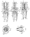
- FIG. 1 to 5 An embodiment of the invention suitable for dead end connections between two wires is illustrated in Figs. 1 to 5.
- a blind central chamber 103 is connected by discrete radial slots 104 to two discrete radially offset blind ended chambers 105.
- the gap of the slots 104 is narrower than the diameter of the wire to be housed therein.
- Provision of a conical enlargement 106 at the open end of each chamber 105 correspondingly produces a convergent entrance 107 leading into the open end of each said slot 104 which results in the formation of profiled shoulder means (SM) between the points 108-109-110 in relation to each chamber 105.
- SM profiled shoulder means
- the said braking effect causes the joining portions 116-117 to overlap and contact at intermediate portions 118-119 of said joining portions, in commencement of a twist connection between the said joining portions, which in response to further relative rotation between the said members, culminates in the formation of a tightly conjoined spiral dead end joint between said joining portions 116-117 of the wires 113-114 (see Fig. 5).
- the joint After completing the joint, it is housed in the blind central chamber 103 in the member 101 and the members 101 and 102 are united in face to face contact by means of headed lugs 120 common to both members.
- the heads of said lugs may be profiled to suit co-operative engagement with corresponding surfaces upon each member, in either a snap connection or by a cammed bayonet connection.
- the headed lugs illustrated are intended to perform the bayonet type connection referred to, whereby a tight engagement of the raised lands 125 is accomplished by passing the headed lugs 120 of the respective members 101 and 102 through respective apertures 123 in opposing said members in order to bring the said lands of opposed members 101 and 102 into radially misaligned face to face contact, then contra rotating said members (30 degrees as illustrated), simultaneously to align the lands whilst forcing them into tight engagement by virtue of the reaction between correspondingly profiled camming surfaces, being respectively the inner edges 121 of the elevated head portions 122 of the headed lugs 120, and the rearwardly facing outwardly disposed surfaces 124 in the apertures 123.
- the members may be provided with collars 5 and releasably coupled together with a sleeve 9 (as described below with reference to Figs. 6 and 7) prior to commencement of the twist connection, whereby the joining portions 116 and 117 of the wires 113 and 114 to be joined, are dragged through the restricted radial slots 104 from the chambers 105 as contra rotation of the members 101 and 102 begins, thereafter to progressively transfer into the central chamber 103 and said joining portions 116 and 117 spirally conjoin towards the blind bottom of said central chamber 103 during the continued contra rotation of the members 101 and 102; and whereby the interference fit of said joining portions in the slots 104 imposes a frictional grip upon each said joining portion as they drag through said slots, thereby to maintain the required braking effect to both wires to ensure a tightly twisted spiral joint.
- a sleeve 9 as described below with reference to Figs. 6 and 7
- Figures 6 and 7 show a connector having a similar arrangement of chambers that can be used to produce inline connections between wires.
- the connector illustrated therein comprises two identical members 1 and 2 each having a body 3 which is wider than it is thick and at one end of the body 3 there is a head 4 of circular cross-section having a collar 5 also of circular cross-section at the forward end thereof.
- the collar 5 has an annular front end face 6 with a conical face 7 extending outwardly and rearwardly from the end face 6 and terminating in an engagement shoulder 8, which is preferably angled rearwardly as shown.
- the two members 1 and 2 are coupled by a sleeve 9 which is generally annular in shape with inwardly directed circular ribs 10 inward of outwardly expanding conical contact faces 11.
- the internal diameter of the ribs 10 is less than the external diameter of the engagement shoulder 8 and thus there is an interference engagement between the inner faces 12 of the ribs 10 and the shoulders 8 which is facilitated by the engaging action of the faces 7 and 11 as the members 1 and 2 are pushed together with the sleeve 9 therebetween.
- another form of connection would be to mount the sleeve 9 on one member 1 or 2 and then insert the collar of the other member into the sleeve.
- the collar would be integral with one of the members 1 or 2 and would be profiled internally as just described to snap engage over the shoulder 8 of the other member.
- the sleeve 9 may also be resiliently deflectable to permit engagement with the collars 5.
- the construction of the components from a suitably elastic plastics material is envisaged so as to provide for the required ability to deflect resiliently and achieve a snap connection.
- the foregoing is the preferred form of engagement between the collars and the sleeve as it forms a seal to prevent the ingress of moisture or corrosive agents which could affect the joint.
- the seal is formed by virtue of the residual forces within the expanded sleeve causing it to bear on the collar 5, Figs. 6 and 7, to form a high pressure low contact area along a narrow line of contact and thus to provide a good seal.
- a better understanding of the interaction of the components forming the snap connection can be obtained from the enlarged fragmentary view of Fig. 7.
- forwardly of the collar 5 may be made up of a plurality of fingers to facilitate the snap connection, or the sleeve ends may be longitudinally slit to provide fingers, thereby to facilitate the snap connection.
- the members 1 and 2 are relatively rotatable and the faces 6 are optionally provided with teeth to position the members in a relative rotational position.
- These teeth are of ratchet type allowing only one direction of relative rotational movement of one member relative to the other. The reason is to prevent the unwinding of a wire joint after its formation.
- the members 1 and 2 are substantially identical and include an axial chamber means configured to have a central chamber 14 therethrough from the end face 6 to the rear end face 16 and at least one side chamber 15.
- the side chamber 15 may extend through the rear face 16 or may be blind, but is open to the front end of the members 1 and 2. As illustrated in Fig. 6, the side chamber 15 is blind at the rear end 17 and is circular in cross section, but other shapes are also possible.
- the side chamber 15 is interconnected with the chamber 14 by a slot the gap of which is less than the diameter of the wire to be joined with the wire in the chamber 14.
- a counterbore 18 may be provided as shown in Figure 8.
- each wire has a holding portion that lies within the chamber 14 of a respective member 1 and 2 and a joining portion that is inserted into a side chamber 15 of the other respective member 1 and 2.
- the overlapping within the chamber 14 is essential (in this embodiment of the invention) to promote the frictional drag brake effect referred to above across the shoulder means (SM).
- SM shoulder means
- end to end connection could also be provided as might be preferred for particular configurations of the members 1 and 2/101 and 102.
- the stripper comprises an end extension 36 of the members 1 and 2 preferably coupled thereto by a frangible zone 37.
- the extension has a slot 38 therealong and a tapered entry 39 to the slot.
- the edges of the slot 38 and entry 39 are angled to provide a cutting edge 40.
- the slot 38 ideally is slightly greater in width than the diameter of the conductor of the wire and the tapered entry 39 has a maximum width greater than the diameter of the insulation.
- the procedure is to place the wire with the required length to be stripped above the extension 36 and then force the insulated wire into and through the tapered entry 39 into the slot 38 preferably with a part or full rotation to cause the cutting edge to sever the insulation. Then by holding the wire and pulling the member 1 away from the wire the severed insulation is stripped from the conductor leaving it bared for insertion into its channel in the member 1. If desired the wire can be inserted into the slots of the extensions of two oppositely opposed relatively inverted members 1 and 2 and then by pulling the members apart the stripping is effected. Either form of stripping can be adopted.
- extensions 36 can be broken off, if desired.
- annular sealing flap can be used to embrace a wire passing through the chamber 14, the forward angle of the flap facilitating the passage of the wire through the chamber 14.
- FIG. 6 An alternative rear opening seal arrangement is illustrated in Fig. 6. This arrangement is preferred when material inflexibility of the moulded member prevents the proper functioning of the flap type seal and when a modified embodiment, utilising a wire to wire overlap, as opposed to a wire to insulation overlap in the chambers 14, is used for electrical wires.
- the alternative seal relies upon a gradual tapered entry into the through opening in the rear end of the member wherein the minimum diameter of the entry is less than the insulation diameter of the wire. The insulation is pushed into the tapered entry as far as it will go when mounting the wire in the member. Thereafter the formation of the spiral joint draws upon this portion of the wire, dragging the insulated shrouding tightly into the tapered entry thus forming a watertight seal.
- the members are desirably of a deformable nature as there is a phase in the creation of the twist tie between the wires where they are forced one over the other in overlapping relationship within the chamber 14 by the shoulder means (SM), requiring deformation of the member.
- SM shoulder means
- the members can be formed from material which can be moulded and which has appropriate heat and electrical insulation properties.
- the material should also be sufficiently hard to allow the cutting edges of the slot and entry thereto, 38-39, to sever the insulation around a conductor.
- a typical material would be glass filled PET, such as DuPont "Rynite” (trade mark) grade PR530 and FR515.
- these connectors can have more than one channel associated with the chamber 14 in order to join more than two wires in one connection.
- Other variations can be adopted without departing from the inventive concept and method as hereinbefore defined.
Landscapes
- Engineering & Computer Science (AREA)
- Manufacturing & Machinery (AREA)
- Connections Effected By Soldering, Adhesion, Or Permanent Deformation (AREA)
- Coating With Molten Metal (AREA)
- Ropes Or Cables (AREA)
- Manufacturing Of Electrical Connectors (AREA)
- Wire Processing (AREA)
Claims (17)
- Ein Verbinder zur Bildung einer Drallverbindung zwischen ersten und zweiten biegsamen Drähten (113, 114), wobei der Verbinder umfaßt: erste und zweite Elemente (1, 2, 101, 102), jeweils mit einer Kammer, die von ersten Enden der entsprechenden Elemente (1, 2, 101, 102) zugänglich ist, um zu verbindende Drähte (113, 114) Seite an Seite aufzunehmen und zu positionieren, wobei die Kammer (14, 15, 103, 104, 105) von wenigstens einem Element (1, 2, 101) eine ein Moment anlegende Schulter (SM, 108, 109, 110) aufweist und eine auf das Moment reagierende Schulter (SM, 108, 109, 110) in Nachbarschaft zu dem ersten Ende des zugeordneten Elementes (1, 2, 101, 102) Innenflächen von jeder Kammer (14, 15, 103, 104, 05) sind, gegen welche die Drähte (113, 114) während der relativen Drehung der Elemente (1, 2, 101, 102) geklemmt werden; dadurch gekennzeichnet, daß die Kammer (14, 14, 103, 104, 105) von wenigstens einem Element (1, 2, 101) ferner Bremsmittel umfaßt, die gegen eine relative Längsbewegung der Drähte (113, 114) durch Zwangseingriff mit den Drähten während der Relativdrehung der Elemente (1, 2, 101, 102) wirken.
- Ein Verbinder, wie in Anspruch 1 definiert, wobei die Kammer eine zentrale Kammer (14, 103) umfaßt, die beide Drähte (113, 114) aufnehmen kann, wenn sie zusammen verdrillt werden und erste und zweite Seitenkammern (15, 105), die mit der zentralen Kammer (14, 103) durch Schlitze (104) verbunden sind, deren Spalt kleiner als der Durchmesser von jedem der Drähte (113, 114) ist, wobei die Seitenkammern (15, 105) einen solchen Querschnitt aufweisen, daß die zwei Drähte (113, 114) nicht gleichzeitig eine Seitenkammer (15, 105) belegen können.
- Ein Verbinder, wie in Anspruch 2 definiert, umfassend Abschrägungen (106), um die Eintrittsenden der Seitenkammern (15, 105) in Nachbarschaft zu dem ersten Ende von dem wenigstens einen Element (1, 2, 101), um ein vergrößertes Eintrittsende für die Seitenkammern (5, 105) vorzugeben und ferner innerhalb der Schlitze (104) Schnittlinien zwischen den Abscbrägungen (106) und den Schlitzen (104) vorzugeben, wobei die Schnittlinien die das Moment anlegende Schulter (SM, 108, 109, 110) vorgeben.
- Ein Verbinder, wie in irgendeinem vorhergehenden Anspruch definiert, wobei die Elemente (1, 2, 101, 102) deformierbar sind.
- Ein Verbinder, wie in irgendeinem vorhergehenden Anspruch definiert und eine freigebbare Kupplungseinrichtung (5, 9, 120, 123) umfassend, wobei verkettete Elemente (1, 2, 101, 102) mit ihren ersten Enden Fläche an Fläche anliegend, miteinander gekoppelt sind.
- Ein Verbinder, wie in Anspruch 5 definiert, umfassend eine Kupplung in der Form einer freigebbaren nachgiebig eingreifenden Hülse (9) für die Verbindung der Elemente (1, 2) miteinander.
- Ein Verbinder, wie in Anspruch 5 definiert, umfassend eine Kupplung in der Form eines erweiterten Kragens (9) an dem ersten Ende des ersten Elementes (1), wobei der Kragen eine Bohrung besitzt, die einen zusammenwirkenden Ringflansch übergreift und mit diesem nachgiebig in Eingriff gelangen kann, der sich von dem ersten Ende des zweiten Elementes (2) erstreckt, um hierdurch die Elemente (1, 2) miteinander zu verbinden.
- Ein Verbinder, wie in irgendeinem der Ansprüche 5 bis 7 definiert, wobei die Kupplungseinrichtung (5, 9, 120, 123) den Elementen (1, 2, 101, 102) eine relative Drehung erlaubt, während sie miteinander verbunden sind.
- Ein Verbinder, wie in Anspruch 8 definiert, wobei die ersten Enden der Elemente (1, 2, 101, 102) mit Anschlageinrichtungen versehen und mit diesen in Eingriff gelangen, wenn die Elemente (1, 2, 101, 102) miteinander verbunden sind, um hierdurch in Drehrichtung die Elemente (1, 2, 101, 102) zu positionieren, wobei die Anschlageinrichtung in der Lage ist, zwangsläufig während der Relativdrehung der Elemente (1, 2, 101, 102) übersteuert zu werden.
- Ein Verbinder, wie in Anspruch 9 definiert, wobei die Anschlageinrichtung nur in einer Drehrichtung übersteuert werden kann.
- Ein Verbinder, wie in irgendeinem vorhergehenden Anspruch definiert, wobei die Elemente (101. 102) an ihren ersten Enden mit Fingern mit Verriegelungsansätzen (120) und Öffnungen mit zusammenwirkenden geneigten Verriegelungsflächen (123) versehen sind, so daß der Einsatz der Finger in die Öffnungen, gefolgt von einer teilweisen relativen Drehung der Elemente (101. 102), den Eingriff der Verriegelungseinsätze (120) mit den Verriegelungsflächen (123) in einer kämmenden Wirkung hervorruft, wodurch die Elemente (101, 102) in eine aneinander anliegende Beziehung gezogen werden.
- Ein Verbinder, wie in Anspruch 11 definiert, umfassend Abdichtflächen (125), die den Zugang der Kammer (14, 15, 103, 104, 105) von dem ersten Ende beider Elemente (101, 102) umgeben, welche Flächen durch die kämmende Wirkung in Kontakt gezwungen werden.
- Ein Verbinder, wie in Anspruch 12 definiert, wobei die Abdichtfläche (125) an dem ersten Ende von wenigstens einem der Elemente (101, 102) ein kontinuierlich ansteigender Steg (125) ist.
- Ein Verbinder. wie in irgendeinem vorhergehenden Anspruch definiert und ferner umfassend einen Isolationsschneider, der sich von wenigstens einem der Elemente (1, 2, 101, 102) an einem Ende gegenüber dem ersten Ende desselben erstreckt, wobei der Schneider ein Paar von Fingern (36) umfaßt, mit einem Abstand (38) zwischen den ersten Fingerteilen in Nachbarschaft zu dem gegenüberliegenden Ende des Elementes (1, 2), der im wesentlichen gleich, aber nicht geringer als der Durchmesser des in der Kammer (14, 15, 104) des Elementes (1, 2) zu montierenden Drahtes ist, und mit einem Abstand (39) zwischen den weiteren Fingerteilen, die sich von den ersten Fingerteilen zu freien Enden der Finger entfernt von den ersten Fingerteilen erstrecken, der von den ersten Fingerteilen hinweg auseinanderläuft zum Schneiden von Profilen an gegenüberliegenden Kanten (40) der Finger (36), wobei isolierte Drähte (113, 114), die zwischen den Fingern in den Raum zwischen den ersten Fingerteilen gezwungen und gedreht werden, am Umfang der Isolierung abgetrennt werden.
- Ein Verbinder, wie in Anspruch 14 definiert, wobei der Isolationsschneider brechbar mit seinem zugeordneten Element (1, 2) verbunden (37) ist.
- Ein Verbinder, wie in irgendeinem vorhergehenden Anspruch definiert, umfassend eine nachgiebige Abdichtung, um abdichtend einen Draht zu umgeben, der in eine der Kammern (14, 15, 103, 104, 105) eintritt.
- Ein Verfahren zur Bildung einer Drallverbindung zwischen zwei biegsamen Drähten (113, 114), wobei das Verfahren die Schritte umfaßt:Vorgabe eines Verbinders, der zwei Elemente (1, 2, 101, 102) umfaßt, wobei jedes Element (1, 2, 101, 102) eine Drahtaufnahmekanmer (14, 15, 103, 104, 105) umfaßt zur Aufnahme von Drähten (113, 114), die in einer Beziehung Seite an Seite zu verbinden sind und eine ein Moment anlegende Schulter (SM, 108, 109, 110) und eine auf das Moment reagierende Schulter (SM, 108, 109, 110) in jeder Kammer (14, 15, 103, 104, 105); undentgegengesetzte Drehung dieser Elemente (1, 2, 101, 102) mit in der Kammer (14, 15, 103, 104, 105) positionierten Drähten (113, 114), um die Drähte (113, 114) der Reihe nach in Kontakt mit der auf das Moment reagierenden Schulter (SM, 108, 109, 110) durch die das Moment anlegende Schulter (SM, 108, 109, 110) zu zwingen, um sich einander zu kreuzen und mit einander in Eingriff zu gelangen und jeden um den anderen zu verdrillen, um eine Drallverbindung von verriegelten Spiralen zu bilden;dadurch gekennzeichnet, daß wenigstens ein Element eine seiner Kammer (14, 15, 103, 104, 105) zugeordnete Bremseinrichtung (104) besitzt und daß die Drähte (113, 114) gegen eine relative Längsbewegung während der entgegengesetzten Drehung gebremst werden durch Zwangseingriff mit der Bremseinrichtung (104).
Applications Claiming Priority (3)
| Application Number | Priority Date | Filing Date | Title |
|---|---|---|---|
| AUPK028990 | 1990-05-23 | ||
| AU289/90 | 1990-05-23 | ||
| PCT/AU1991/000223 WO1991018430A1 (en) | 1990-05-23 | 1991-05-23 | Method and apparatus for twist connecting wires |
Publications (3)
| Publication Number | Publication Date |
|---|---|
| EP0484498A1 EP0484498A1 (de) | 1992-05-13 |
| EP0484498A4 EP0484498A4 (en) | 1995-08-30 |
| EP0484498B1 true EP0484498B1 (de) | 1998-08-12 |
Family
ID=3774707
Family Applications (1)
| Application Number | Title | Priority Date | Filing Date |
|---|---|---|---|
| EP91910136A Expired - Lifetime EP0484498B1 (de) | 1990-05-23 | 1991-05-23 | Verfahren und vorrichtung zur drallverbindung von drähten |
Country Status (7)
| Country | Link |
|---|---|
| EP (1) | EP0484498B1 (de) |
| JP (1) | JPH05500288A (de) |
| KR (1) | KR920704376A (de) |
| AT (1) | ATE169778T1 (de) |
| CA (1) | CA2063999A1 (de) |
| DE (1) | DE69129967T2 (de) |
| WO (1) | WO1991018430A1 (de) |
Families Citing this family (4)
| Publication number | Priority date | Publication date | Assignee | Title |
|---|---|---|---|---|
| FR2751482B1 (fr) * | 1996-07-18 | 1998-09-04 | Sylea | Dispositif pour la realisation d'une epissure |
| US6010049A (en) | 1997-08-22 | 2000-01-04 | Stein; John P. | Carrier for a trailer-hitch receiver |
| JP5191923B2 (ja) | 2009-02-17 | 2013-05-08 | 矢崎総業株式会社 | 電線の接続方法 |
| JP5723112B2 (ja) | 2010-07-05 | 2015-05-27 | 矢崎総業株式会社 | 絶縁電線の接続構造及び接続方法 |
Family Cites Families (7)
| Publication number | Priority date | Publication date | Assignee | Title |
|---|---|---|---|---|
| US1539723A (en) * | 1922-08-19 | 1925-05-26 | Charles A Deuscher | Electrical connection and method of making the same |
| US1657933A (en) * | 1927-02-15 | 1928-01-31 | William E Lindsley | Electrical connecter |
| US1763298A (en) * | 1927-05-25 | 1930-06-10 | Eric T Franzen | Wire-end splicing device and connecting guard |
| US2526740A (en) * | 1945-02-16 | 1950-10-24 | American Chain & Cable Co | Cable connector |
| FR2173493A5 (de) * | 1972-02-24 | 1973-10-05 | Micheau Philippe | |
| US4163868A (en) * | 1978-06-02 | 1979-08-07 | Stotts Hugh D | Wire connector |
| DD237561A1 (de) * | 1985-05-21 | 1986-07-16 | Baudirektion Hauptstadt Berlin | Gekapselte unloesbare elektrische leiterverbindung |
-
1991
- 1991-05-23 EP EP91910136A patent/EP0484498B1/de not_active Expired - Lifetime
- 1991-05-23 AT AT91910136T patent/ATE169778T1/de not_active IP Right Cessation
- 1991-05-23 WO PCT/AU1991/000223 patent/WO1991018430A1/en not_active Ceased
- 1991-05-23 CA CA002063999A patent/CA2063999A1/en not_active Abandoned
- 1991-05-23 DE DE69129967T patent/DE69129967T2/de not_active Expired - Fee Related
- 1991-05-23 KR KR1019920700156A patent/KR920704376A/ko not_active Ceased
- 1991-05-23 JP JP3509472A patent/JPH05500288A/ja active Pending
Also Published As
| Publication number | Publication date |
|---|---|
| EP0484498A1 (de) | 1992-05-13 |
| JPH05500288A (ja) | 1993-01-21 |
| WO1991018430A1 (en) | 1991-11-28 |
| KR920704376A (ko) | 1992-12-19 |
| DE69129967T2 (de) | 1999-05-12 |
| DE69129967D1 (de) | 1998-09-17 |
| EP0484498A4 (en) | 1995-08-30 |
| ATE169778T1 (de) | 1998-08-15 |
| CA2063999A1 (en) | 1991-11-24 |
Similar Documents
| Publication | Publication Date | Title |
|---|---|---|
| US5446241A (en) | Apparatus and method for twist connecting wires | |
| US5651699A (en) | Modular connector assembly for coaxial cables | |
| US4684201A (en) | One-piece crimp-type connector and method for terminating a coaxial cable | |
| US8016613B2 (en) | Coaxial connector with locking sleeve for terminating cable | |
| US9153917B2 (en) | Coaxial cable connector | |
| EP2912724B1 (de) | Schnellmontageverbinder für ein koaxialkabel | |
| JP4510770B2 (ja) | ケーブル把持部を備える同軸コネクタ | |
| US6705884B1 (en) | Electrical connector apparatus and method | |
| US12300926B2 (en) | Nut seal connector assembly | |
| US4427253A (en) | Fully insulated electrical clamp connector with inboard insulating tab and slot | |
| US9564695B2 (en) | Torque sleeve for use with coaxial cable connector | |
| US3982808A (en) | Single wire electrical connector | |
| US20070202735A1 (en) | Compression snap electrical connector | |
| US3923367A (en) | Simultaneous double crimp coaxial cable contact assembly | |
| EP0484498B1 (de) | Verfahren und vorrichtung zur drallverbindung von drähten | |
| DE68914739T2 (de) | Elektrischer Verbinder. | |
| EP1821375A2 (de) | Ein Anschlussstück, eine Methode zum Crimpen dieses Anschlussstücks und ein Positioniergestell | |
| GB2197139A (en) | Strain relief bushings | |
| US5035660A (en) | Eccentric electrical cable connecting device | |
| US4695110A (en) | Electrical connector apparatus | |
| US6684439B2 (en) | Coaxial cable termination tool | |
| AU645806B2 (en) | Method and apparatus for twist connecting wires | |
| WO2020150524A1 (en) | Compression connectors with insulating cover | |
| KR100214781B1 (ko) | 관접속구 | |
| EP0052037A2 (de) | Isolation durchstechender Kontakt |
Legal Events
| Date | Code | Title | Description |
|---|---|---|---|
| PUAI | Public reference made under article 153(3) epc to a published international application that has entered the european phase |
Free format text: ORIGINAL CODE: 0009012 |
|
| 17P | Request for examination filed |
Effective date: 19920212 |
|
| AK | Designated contracting states |
Kind code of ref document: A1 Designated state(s): AT BE CH DE DK ES FR GB GR IT LI LU NL SE |
|
| A4 | Supplementary search report drawn up and despatched | ||
| AK | Designated contracting states |
Kind code of ref document: A4 Designated state(s): AT BE CH DE DK ES FR GB GR IT LI LU NL SE |
|
| 17Q | First examination report despatched |
Effective date: 19960216 |
|
| GRAG | Despatch of communication of intention to grant |
Free format text: ORIGINAL CODE: EPIDOS AGRA |
|
| GRAG | Despatch of communication of intention to grant |
Free format text: ORIGINAL CODE: EPIDOS AGRA |
|
| GRAH | Despatch of communication of intention to grant a patent |
Free format text: ORIGINAL CODE: EPIDOS IGRA |
|
| RAP1 | Party data changed (applicant data changed or rights of an application transferred) |
Owner name: MACKANESS, JAMES BELLAMY |
|
| RIN1 | Information on inventor provided before grant (corrected) |
Inventor name: PUCHY, DAVID PETER WILLIAM Inventor name: MACKANESS, JAMES BELLAMY |
|
| GRAH | Despatch of communication of intention to grant a patent |
Free format text: ORIGINAL CODE: EPIDOS IGRA |
|
| GRAA | (expected) grant |
Free format text: ORIGINAL CODE: 0009210 |
|
| AK | Designated contracting states |
Kind code of ref document: B1 Designated state(s): AT BE CH DE DK ES FR GB GR IT LI LU NL SE |
|
| PG25 | Lapsed in a contracting state [announced via postgrant information from national office to epo] |
Ref country code: IT Free format text: LAPSE BECAUSE OF FAILURE TO SUBMIT A TRANSLATION OF THE DESCRIPTION OR TO PAY THE FEE WITHIN THE PRE;WARNING: LAPSES OF ITALIAN PATENTS WITH EFFECTIVE DATE BEFORE 2007 MAY HAVE OCCURRED AT ANY TIME BEFORE 2007. THE CORRECT EFFECTIVE DATE MAY BE DIFFERENT FROM THE ONE RECORDED.SCRIBED TIME-LIMIT Effective date: 19980812 Ref country code: LI Free format text: LAPSE BECAUSE OF FAILURE TO SUBMIT A TRANSLATION OF THE DESCRIPTION OR TO PAY THE FEE WITHIN THE PRESCRIBED TIME-LIMIT Effective date: 19980812 Ref country code: AT Free format text: LAPSE BECAUSE OF FAILURE TO SUBMIT A TRANSLATION OF THE DESCRIPTION OR TO PAY THE FEE WITHIN THE PRESCRIBED TIME-LIMIT Effective date: 19980812 Ref country code: GR Free format text: LAPSE BECAUSE OF NON-PAYMENT OF DUE FEES Effective date: 19980812 Ref country code: ES Free format text: THE PATENT HAS BEEN ANNULLED BY A DECISION OF A NATIONAL AUTHORITY Effective date: 19980812 Ref country code: BE Free format text: LAPSE BECAUSE OF FAILURE TO SUBMIT A TRANSLATION OF THE DESCRIPTION OR TO PAY THE FEE WITHIN THE PRESCRIBED TIME-LIMIT Effective date: 19980812 Ref country code: CH Free format text: LAPSE BECAUSE OF FAILURE TO SUBMIT A TRANSLATION OF THE DESCRIPTION OR TO PAY THE FEE WITHIN THE PRESCRIBED TIME-LIMIT Effective date: 19980812 Ref country code: NL Free format text: LAPSE BECAUSE OF FAILURE TO SUBMIT A TRANSLATION OF THE DESCRIPTION OR TO PAY THE FEE WITHIN THE PRESCRIBED TIME-LIMIT Effective date: 19980812 |
|
| REF | Corresponds to: |
Ref document number: 169778 Country of ref document: AT Date of ref document: 19980815 Kind code of ref document: T |
|
| REG | Reference to a national code |
Ref country code: CH Ref legal event code: EP |
|
| REF | Corresponds to: |
Ref document number: 69129967 Country of ref document: DE Date of ref document: 19980917 |
|
| PG25 | Lapsed in a contracting state [announced via postgrant information from national office to epo] |
Ref country code: SE Free format text: LAPSE BECAUSE OF FAILURE TO SUBMIT A TRANSLATION OF THE DESCRIPTION OR TO PAY THE FEE WITHIN THE PRESCRIBED TIME-LIMIT Effective date: 19981112 Ref country code: DK Free format text: LAPSE BECAUSE OF FAILURE TO SUBMIT A TRANSLATION OF THE DESCRIPTION OR TO PAY THE FEE WITHIN THE PRESCRIBED TIME-LIMIT Effective date: 19981112 |
|
| ET | Fr: translation filed | ||
| NLV1 | Nl: lapsed or annulled due to failure to fulfill the requirements of art. 29p and 29m of the patents act | ||
| REG | Reference to a national code |
Ref country code: CH Ref legal event code: PL |
|
| PG25 | Lapsed in a contracting state [announced via postgrant information from national office to epo] |
Ref country code: LU Free format text: LAPSE BECAUSE OF NON-PAYMENT OF DUE FEES Effective date: 19990523 Ref country code: GB Free format text: LAPSE BECAUSE OF NON-PAYMENT OF DUE FEES Effective date: 19990523 |
|
| PLBE | No opposition filed within time limit |
Free format text: ORIGINAL CODE: 0009261 |
|
| STAA | Information on the status of an ep patent application or granted ep patent |
Free format text: STATUS: NO OPPOSITION FILED WITHIN TIME LIMIT |
|
| 26N | No opposition filed | ||
| GBPC | Gb: european patent ceased through non-payment of renewal fee |
Effective date: 19990523 |
|
| PG25 | Lapsed in a contracting state [announced via postgrant information from national office to epo] |
Ref country code: FR Free format text: LAPSE BECAUSE OF NON-PAYMENT OF DUE FEES Effective date: 20000131 |
|
| PG25 | Lapsed in a contracting state [announced via postgrant information from national office to epo] |
Ref country code: DE Free format text: LAPSE BECAUSE OF NON-PAYMENT OF DUE FEES Effective date: 20000301 |
|
| REG | Reference to a national code |
Ref country code: FR Ref legal event code: ST |