EP0484553B1 - Anzeige für den ausgang eines motors eines motorfahrzeuges - Google Patents
Anzeige für den ausgang eines motors eines motorfahrzeuges Download PDFInfo
- Publication number
- EP0484553B1 EP0484553B1 EP91909704A EP91909704A EP0484553B1 EP 0484553 B1 EP0484553 B1 EP 0484553B1 EP 91909704 A EP91909704 A EP 91909704A EP 91909704 A EP91909704 A EP 91909704A EP 0484553 B1 EP0484553 B1 EP 0484553B1
- Authority
- EP
- European Patent Office
- Prior art keywords
- output
- engine
- torque
- displaying
- calculated
- Prior art date
- Legal status (The legal status is an assumption and is not a legal conclusion. Google has not performed a legal analysis and makes no representation as to the accuracy of the status listed.)
- Expired - Lifetime
Links
- 239000000446 fuel Substances 0.000 description 15
- 230000005540 biological transmission Effects 0.000 description 3
- 239000007789 gas Substances 0.000 description 3
- 238000002347 injection Methods 0.000 description 3
- 239000007924 injection Substances 0.000 description 3
- 230000004913 activation Effects 0.000 description 2
- 238000002485 combustion reaction Methods 0.000 description 2
- 230000001133 acceleration Effects 0.000 description 1
- 230000002411 adverse Effects 0.000 description 1
- 230000008859 change Effects 0.000 description 1
- 239000000498 cooling water Substances 0.000 description 1
- 238000010586 diagram Methods 0.000 description 1
- 238000006073 displacement reaction Methods 0.000 description 1
- 238000004880 explosion Methods 0.000 description 1
- 230000007246 mechanism Effects 0.000 description 1
- 238000000034 method Methods 0.000 description 1
- 238000012986 modification Methods 0.000 description 1
- 230000004048 modification Effects 0.000 description 1
- 230000008569 process Effects 0.000 description 1
- 238000011144 upstream manufacturing Methods 0.000 description 1
Images
Classifications
-
- G—PHYSICS
- G01—MEASURING; TESTING
- G01L—MEASURING FORCE, STRESS, TORQUE, WORK, MECHANICAL POWER, MECHANICAL EFFICIENCY, OR FLUID PRESSURE
- G01L3/00—Measuring torque, work, mechanical power, or mechanical efficiency, in general
- G01L3/24—Devices for determining the value of power, e.g. by measuring and simultaneously multiplying the values of torque and revolutions per unit of time, by multiplying the values of tractive or propulsive force and velocity
Definitions
- the present invention relates to a display unit for measuring and displaying the output or torque of a vehicle engine while the engine is normally operating.
- Torque produced by the engine is not usually displayed or used as data for various control mechanisms such as an automatic transmission. The reason for this is because it is not easy to detect the torque when the vehicle is running.
- a torque sensor may also be used to precisely detect minimal torsion of shafts interposed in a power transmission system. This torque sensor is expensive.
- This output display unit provides a display of figures during deceleration in which the output and basic torque of the engine is actually zero. This happens in some vehicles and lowers the commercial value of the display unit.
- AB valve anti-afterburning valve
- BC valve boost control valve
- the BC valve introduces air into the intake manifold to maintain a predetermined negative pressure in the intake manifold during the deceleration (a deceleration negative pressure correction function).
- Patent Abstracts of Japan, Volume 8, No. 16 (M-270), 24 January 1984 and JP-A-5817728 disclose a device for displaying the optimum rotational speed for changing the shift position for minimizing the fuel consumption which derives the actual fuel consumption rate on the basis of a speed signal, an engine rotational speed signal and a air flow meter signal.
- the engine load is derived from the rotational speed of the engine and from the intake air amount.
- the torque is calculated on the basis of these data by means of a map.
- the fuel consumption rate can be derived so as to determine a speed change shift position for minimizing the fuel consumption.
- US-A-3847019 discloses a device for measuring the engine output and the engine torque on the basis of a signal representing the weight of the intake air introduced into the engine.
- the signal representing the weight of the intake air is multiplied by an electrical functional signal for generating an output signal which is proportional to the variation of the engine output.
- a main object of the invention is to provide an output display unit for a vehicle engine, which displays zeros when AB and BC valves of the engine are active just after deceleration, thereby improving a commercial value of the display unit.
- Another object of the invention is to achieve the above main object with use of parameters that can be detected by existing sensors, and correctly display the output and torque of the engine.
- An output display unit for a vehicle engine comprises the following means (a) to (f):
- the invention calculates an engine output for a predetermined steady run corresponding to a detected vehicle speed. If an engine output calculated according to the intake air quantity and rotational speed of the engine is smaller than the engine output for the steady run, the invention determines that the output has been caused by activation of the AB and BC valves. In this case, the invention displays zeros because the engine provides no output, thereby correctly displaying the engine output.
- the fifth means may calculate the engine output by calculating engine torque according to the intake air quantity and rotational speed of the engine, and by calculating the engine output according to the torque and rotational speed.
- the sixth means is preferred to have a torque display function displaying zeros as torque when the torque calculated by the fifth means is smaller than that calculated by the fourth means, and displays the torque calculated by the fifth means as it is in the other cases.
- the fourth means may have a table that stores predetermined engine outputs corresponding to various steady runs with respect to different engine speeds. One of the stored engine outputs for the steady runs is retrieved out of the table according to a detected vehicle speed.
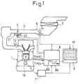
- an engine 1 is connected to an air cleaner 2 through an intake path 3 in which a throttle valve 4 is disposed.
- a throttle valve 4 On the downstream side of the throttle valve 4, there is a solenoid fuel injection valve 5 arranged for each cylinder to supply a fuel to an intake port of the cylinder.
- An auxiliary air path 21 bypassing the throttle valve 4 has a solenoid auxiliary air control valve 22, which provides functions of the AB and BC valves.
- a hot-wire airflow meter 6 (a first means) for detecting an intake air quantity Q to the engine 1 is arranged, for example, on the upstream side of the throttle valve 4 in the intake path 3.
- a crank angle sensor 7 (a second means) for generating a pulse signal for every predetermined angle of rotation of a crank shaft 1a is arranged, for example, at an end of the crank shaft 1a of the engine 1. According to the pulse signals, an engine rotational speed N (the number of revolutions per unit time, i.e., RPM) is detected.
- N the number of revolutions per unit time, i.e., RPM
- Signals from the airflow meter 6 and crank angle sensor 7 are transferred to an engine control unit 8 and a measuring unit 9.
- the engine control unit 8 incorporates a controller for forming, together with the fuel injection valve 5 and auxiliary air control valve 22, a fuel control system and an auxiliary air control system.
- the engine control unit 8 also includes a vehicle speed sensor 8a (a third means) for detecting a vehicle speed Vsp according to information related to a transmission and tires, and a steady-run output calculation means 8b (a fourth means) for calculating an engine output for a predetermined steady run (hereinafter referred to as the steady-run output) with respect to the detected vehicle speed Vsp.
- the engine control unit 8 comprises a microcomputer system for controlling operations of the fuel injection valve 5 and auxiliary air control valve 22 according to predetermined programs.
- a function of the steady-run output calculation means 8b is also achieved by executing a predetermined program.
- the measuring unit 9 calculates the torque (Kg m) and output (PS) of the engine 1 from time to time.
- the measuring unit 9 comprises a circuit portion and a casing that are integrally formed. On the front face of the casing a display 10 for digitally displaying a result of the calculation is arranged.
- the measuring unit 9 with the display 10 is arranged on, for example, a dashboard in front of a driver's seat.
- the measuring unit 9 comprises a microcomputer system (a fifth means), which receives signals from the airflow meter 6 and crank angle sensor 7 and calculates an engine output P according to the signals.
- the display 10 (a sixth means) compares the output of the measuring unit 9 with the output of the steady-run output calculation means 8b, and displays 0s when the output of the measuring unit 9 is smaller than the output of the steady-run output calculation means 8b, and displays the calculated output of the measuring unit 9 as it is in the other cases.
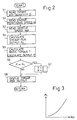
- FIG. 2 is a flowchart schematically showing a program repeatedly executed in the engine control unit 8 (the steady-run output calculation means 8b) and measuring unit 9.
- Step 1 (indicated as S1 in the figure) reads an intake air quantity Q obtained according to a detected signal from the airflow meter 6, and Step 2 reads an engine rotational speed N obtained according to a detected signal from the crank angle sensor 7.
- Step 3 reads a vehicle speed Vsp obtained according to a detected signal from the vehicle speed sensor 8a.
- Step 4 looks up a table, which has been prepared and stored according to a correlational graph (Fig. 3) of experimentally obtained vehicle speeds Vsp and steady-run outputs Pc, and retrieves out of the table a steady-run output Pc corresponding to the vehicle speed Vsp read in Step 3.
- K2 relates to torque for the rotation of the engine itself and is mainly determined according to the size of displacement.
- Step 6 compares to engine output P with the steady-run output Pc.
- Step 7 zeroes the torque T and output P
- Step 8 displays 0s as torque and output indications on the display 10 disposed on the front face of the measuring unit 9.
- Step 8 displays the torque T and output P calculated in Step 5 on the display 10 disposed on the front face of the measuring unit 9.
- the embodiment provides correct indications. Accordingly, a driver may always know the torque T and output P of the engine during driving and is convenient for determining speed changing timing, etc.
- the torque T, etc., thus obtained may be used not only for display purposes but also as input data for traction control.
- the invention displays 0s even if there is a flow of air due to operation of the AB or BC valve when there is no output of the engine during deceleration. In this way, the invention correctly and easily displays an engine output at a low cost with the use of existing sensors, thereby improving the commercial value of the display unit.
- the invention improves the commercial value of the display unit and is very useful in industry.
Landscapes
- Chemical & Material Sciences (AREA)
- Engineering & Computer Science (AREA)
- Combustion & Propulsion (AREA)
- Physics & Mathematics (AREA)
- General Physics & Mathematics (AREA)
- Combined Controls Of Internal Combustion Engines (AREA)
- Force Measurement Appropriate To Specific Purposes (AREA)
- Instrument Panels (AREA)
- Control Of Vehicle Engines Or Engines For Specific Uses (AREA)
Claims (6)
- Eine Anzeigeeinheit (10) zum Anzeigen der Leistungsabgabe eines Fahrzeugmotors mit folgenden Merkmalen:
einer ersten Einrichtung (S1) zum Erfassen einer Ansaugluftmenge (Q) zu dem Motor,
einer zweiten Einrichtung (S2) zum Erfassen einer Motordrehzahl (N),
gekennzeichnet durch
eine dritte Einrichtung (S3) zum Erfassen einer Fahrzeuggeschwindigkeit (Vsp),
eine vierte Einrichtung (S4) zum Berechnen einer Motorleistungsabgabe (Pa) für einen vorbestimmten stabilen Laufzustand entsprechend der Fahrzeuggeschwindigkeit, die von der dritten Einrichtung (S3) erfaßt wird,
eine fünfte Einrichtung (S5) zum Berechnen einer Motorleistungsabgabe (P) entsprechend der Ansaugluftmenge, die von der ersten Einrichtung (S1) erfaßt wird, und der Drehzahl (N), die von der zweiten Einrichtung (S2) erfaßt wird, und
eine sechste Einrichtung (S7) zum Anzeigen von Nullen als Motorleistungsabgabe, wenn die Leistungsabgabe (P), die von der fünften Einrichtung (S5) berechnet wurde, kleiner ist als die Leistungsabgabe (Pc), die von der vierten Einrichtung (S4) berechnet wurde, und andernfalls zum Anzeigen der Leistungsabgabe (P), die von der fünften Einrichtung (S5) berechnet wurde. - Eine Anzeigeeinheit zum Anzeigen der Leistungsabgabe eines Fahrzeugmotors gemäß Anspruch 1, dadurch gekennzeichnet,
daß die fünfte Einrichtung (S5) das Drehmoment (T) des Motors entsprechend der Ansaugluftmenge (Q) und der Drehzahl (N) berechnet und ferner die Leistungsabgabe des Motors entsprechend dem Drehmoment und der Drehzahl berechnet. - Eine Anzeigeeinheit zum Anzeigen der Leistungsabgabe eines Fahrzeugmotors gemäß Anspruch 2, dadurch gekennzeichnet,
daß die fünfte Einrichtung (S5) das Drehmoment (T) des Motors entsprechend der Ansaugluftmenge (Q) und der Drehzahl (N) unter Verwendung der folgenden Gleichung berechnet:
- Eine Anzeigeeinheit zum Anzeigen der Leistungsabgabe eines Fahrzeugmotors gemäß Anspruch 2, dadurch gekennzeichnet,
daß die fünfte Einrichtung die Leistungsabgabe (P) des Motors entsprechend dem Drehmoment (T) und der Drehzahl (N) unter Verwendung der folgenden Gleichung berechnet:
- Eine Anzeigeeinheit zum Anzeigen der Leistungsabgabe eines Fahrzeugmotors gemäß Anspruch 2, dadurch gekennzeichnet,
daß die sechste Einrichtung (S7) eine Drehmomentanzeigefunktion zum Anzeigen von Nullen als Drehmoment (T) aufweist, wenn die Leistungsabgabe (P), die von der fünften Einrichtung (S5) berechnet wurde, kleiner ist als die Leistungsabgabe (Pc), die von der vierten Einrichtung (S4) berechnet wurde, und andernfalls das Drehmoment (T) anzeigt, das von der fünften Einrichtung (S5) berechnet wurde. - Eine Anzeigeeinheit zum Anzeigen der Leistungsabgabe eines Fahrzeugmotors gemäß Anspruch 1, dadurch gekennzeichnet,
daß die vierte Einrichtung (S4) eine Tabelle (8) aufweist, die vorbestimmte Motorleistungsabgaben (Pc) speichert, die verschiedenen stabilen Laufzustände bezüglich unterschiedlicher Fahrzeuggeschwindigkeiten (VsP) entsprechen; und daß sie eine der gespeicherten Motorleistungsabgaben (Pc) für die stabilen Laufzustände aus der Tabelle (8) entsprechend der erfaßten Fahrzeuggeschwindigkeit (Vsp) wiedergewinnt.
Applications Claiming Priority (3)
| Application Number | Priority Date | Filing Date | Title |
|---|---|---|---|
| JP130295/90 | 1990-05-22 | ||
| JP2130295A JPH0752129B2 (ja) | 1990-05-22 | 1990-05-22 | エンジン出力表示計 |
| PCT/JP1991/000682 WO1991018270A1 (fr) | 1990-05-22 | 1991-05-22 | Dispositif d'affichage de sortie dans un moteur pour vehicule a moteur |
Publications (3)
| Publication Number | Publication Date |
|---|---|
| EP0484553A1 EP0484553A1 (de) | 1992-05-13 |
| EP0484553A4 EP0484553A4 (en) | 1993-03-03 |
| EP0484553B1 true EP0484553B1 (de) | 1995-08-09 |
Family
ID=15030898
Family Applications (1)
| Application Number | Title | Priority Date | Filing Date |
|---|---|---|---|
| EP91909704A Expired - Lifetime EP0484553B1 (de) | 1990-05-22 | 1991-05-22 | Anzeige für den ausgang eines motors eines motorfahrzeuges |
Country Status (5)
| Country | Link |
|---|---|
| US (1) | US5259241A (de) |
| EP (1) | EP0484553B1 (de) |
| JP (1) | JPH0752129B2 (de) |
| DE (1) | DE69111978T2 (de) |
| WO (1) | WO1991018270A1 (de) |
Families Citing this family (9)
| Publication number | Priority date | Publication date | Assignee | Title |
|---|---|---|---|---|
| US5546755A (en) * | 1995-03-07 | 1996-08-20 | Krieger; Todd N. | Automatic air conditioner shutoff system |
| JP3672316B2 (ja) * | 1995-06-08 | 2005-07-20 | ルノー | 内燃機関のトルク測定装置および方法 |
| FR2735233B1 (fr) * | 1995-06-08 | 1997-07-25 | Renault | Procede et dispositif de mesure du couple d'un moteur thermique a combustion interne prenant en compte les conditions particulieres de combustion |
| DE19615542C2 (de) * | 1996-04-19 | 1998-05-07 | Daimler Benz Ag | Einrichtung zur Motorlastbestimmung für einen Verbrennungsmotor |
| DE19749815B4 (de) * | 1997-11-11 | 2012-04-26 | Robert Bosch Gmbh | Verfahren und Vorrichtung zur Ermittlung der eingespritzten Kraftstoffmenge |
| SE519547C2 (sv) * | 2001-06-18 | 2003-03-11 | Flir Systems Ab | Förfarande och anordning för att åstadkomma en infraröd bild. |
| US6745619B2 (en) | 2001-10-22 | 2004-06-08 | Ford Global Technologies, Llc | Diagnostic method for variable compression ratio engine |
| CN103335762B (zh) * | 2013-07-09 | 2015-01-14 | 中石化石油工程机械有限公司第四机械厂 | 大功率压裂泵车性能试验方法及试验装置 |
| KR101583885B1 (ko) * | 2013-12-18 | 2016-01-08 | 현대자동차주식회사 | 엔진 열 관리 장치 및 방법 |
Family Cites Families (9)
| Publication number | Priority date | Publication date | Assignee | Title |
|---|---|---|---|---|
| JPS5146201B2 (de) * | 1972-05-26 | 1976-12-08 | ||
| JPS57192835A (en) * | 1981-05-23 | 1982-11-27 | Atsugi Motor Parts Co Ltd | Detector for torque signal of internal combustion engine |
| JPS58177728A (ja) * | 1982-04-13 | 1983-10-18 | Toyota Motor Corp | 車両の最適シフト位置表示装置 |
| DE3246798A1 (de) * | 1982-12-17 | 1984-06-20 | Wabco Westinghouse Fahrzeugbremsen GmbH, 3000 Hannover | Anordnung zur messung von motor-drehmomenten |
| JPH01124536A (ja) * | 1987-11-06 | 1989-05-17 | Satake Eng Co Ltd | 包袋の真空包装装置 |
| JPH0792141B2 (ja) * | 1988-05-06 | 1995-10-09 | 日産自動車株式会社 | 自動変速機のライン圧制御装置 |
| JPH02144741A (ja) * | 1988-11-28 | 1990-06-04 | Nec Corp | 半導体記憶装置 |
| JPH0717800Y2 (ja) * | 1989-05-11 | 1995-04-26 | 株式会社ユニシアジェックス | 内燃機関のトルク計測装置 |
| JPH0717803Y2 (ja) * | 1989-08-31 | 1995-04-26 | 株式会社ユニシアジェックス | 自動車用内燃機関の車載型トルク計測装置 |
-
1990
- 1990-05-22 JP JP2130295A patent/JPH0752129B2/ja not_active Expired - Lifetime
-
1991
- 1991-05-22 DE DE69111978T patent/DE69111978T2/de not_active Expired - Fee Related
- 1991-05-22 US US07/781,148 patent/US5259241A/en not_active Expired - Fee Related
- 1991-05-22 WO PCT/JP1991/000682 patent/WO1991018270A1/ja not_active Ceased
- 1991-05-22 EP EP91909704A patent/EP0484553B1/de not_active Expired - Lifetime
Also Published As
| Publication number | Publication date |
|---|---|
| JPH0752129B2 (ja) | 1995-06-05 |
| US5259241A (en) | 1993-11-09 |
| EP0484553A1 (de) | 1992-05-13 |
| DE69111978D1 (de) | 1995-09-14 |
| JPH0425731A (ja) | 1992-01-29 |
| EP0484553A4 (en) | 1993-03-03 |
| WO1991018270A1 (fr) | 1991-11-28 |
| DE69111978T2 (de) | 1996-03-14 |
Similar Documents
| Publication | Publication Date | Title |
|---|---|---|
| JP2757264B2 (ja) | 自動車の駆動成分の適応制御方法及び装置 | |
| EP0482692B1 (de) | Verfahren und Vorrichtung zum Testen eines Drosselklappenpositionssensors | |
| EP0476811B1 (de) | Verfahren und Vorrichtung zum Steuern eines Verbrennungsmotors | |
| GB2121216A (en) | Automatic control of the fuel to an internal combustion engine on deceleration | |
| EP0484553B1 (de) | Anzeige für den ausgang eines motors eines motorfahrzeuges | |
| JP2008057670A (ja) | クラッチの発熱量推定装置 | |
| US5504682A (en) | Method and apparatus for detecting misfires in an internal combustion engine | |
| US4911133A (en) | Fuel injection control system of automotive engine | |
| CN101126357A (zh) | 发动机预节流压力估计 | |
| EP0117313A2 (de) | Steuerungsmethode einer Innenbrennkraftmaschine eine Wiedereichung des Steuerungsprogramms enthaltend | |
| EP0378814B1 (de) | Methode zur Steuerung des Luft-Kraftstoff-Verhältnisses | |
| US6185928B1 (en) | Method and device for detecting misfires in a controlled-ignition internal combustion engine | |
| US6874360B1 (en) | Method of determining rubbing friction torque in a motor vehicle powertrain | |
| EP1148274B1 (de) | Adaptives Verfahren zum Bestimmen des Übergangpunktes auf Zugdrehmoment in einem Antriebstrang mit automatischem Getriebe | |
| US5226323A (en) | Method of and an apparatus for displaying the output of an internal combustion engine | |
| US6568257B2 (en) | Cylinder air charge estimate | |
| JPH04171249A (ja) | 車両用内燃機関の失火検出装置 | |
| KR100188741B1 (ko) | 가변 흡기 시스템의 고장 진단 장치 및 그 방법 | |
| US5728932A (en) | Method for diagnosing performance of intake air amount detection device and apparatus thereof | |
| GB2209074A (en) | Malfunction detection of an engine exhaust gas recirculation system | |
| US20090250037A1 (en) | Control system and control method for internal combustion engine | |
| JPH0717803Y2 (ja) | 自動車用内燃機関の車載型トルク計測装置 | |
| JP2929744B2 (ja) | 内燃機関の空燃比制御装置 | |
| KR100298743B1 (ko) | 자동차의흡입공기량측정방법 | |
| JPH09166038A (ja) | 内燃機関のアイドル回転速度学習制御装置 |
Legal Events
| Date | Code | Title | Description |
|---|---|---|---|
| PUAI | Public reference made under article 153(3) epc to a published international application that has entered the european phase |
Free format text: ORIGINAL CODE: 0009012 |
|
| 17P | Request for examination filed |
Effective date: 19920113 |
|
| AK | Designated contracting states |
Kind code of ref document: A1 Designated state(s): DE GB |
|
| A4 | Supplementary search report drawn up and despatched |
Effective date: 19930111 |
|
| AK | Designated contracting states |
Kind code of ref document: A4 Designated state(s): DE GB |
|
| 17Q | First examination report despatched |
Effective date: 19940405 |
|
| RAP1 | Party data changed (applicant data changed or rights of an application transferred) |
Owner name: UNISIA JECS CORPORATION |
|
| GRAA | (expected) grant |
Free format text: ORIGINAL CODE: 0009210 |
|
| AK | Designated contracting states |
Kind code of ref document: B1 Designated state(s): DE GB |
|
| REF | Corresponds to: |
Ref document number: 69111978 Country of ref document: DE Date of ref document: 19950914 |
|
| PLBE | No opposition filed within time limit |
Free format text: ORIGINAL CODE: 0009261 |
|
| STAA | Information on the status of an ep patent application or granted ep patent |
Free format text: STATUS: NO OPPOSITION FILED WITHIN TIME LIMIT |
|
| 26N | No opposition filed | ||
| PGFP | Annual fee paid to national office [announced via postgrant information from national office to epo] |
Ref country code: GB Payment date: 19990519 Year of fee payment: 9 |
|
| PGFP | Annual fee paid to national office [announced via postgrant information from national office to epo] |
Ref country code: DE Payment date: 19990525 Year of fee payment: 9 |
|
| PG25 | Lapsed in a contracting state [announced via postgrant information from national office to epo] |
Ref country code: GB Free format text: LAPSE BECAUSE OF NON-PAYMENT OF DUE FEES Effective date: 20000522 |
|
| GBPC | Gb: european patent ceased through non-payment of renewal fee |
Effective date: 20000522 |
|
| PG25 | Lapsed in a contracting state [announced via postgrant information from national office to epo] |
Ref country code: DE Free format text: LAPSE BECAUSE OF NON-PAYMENT OF DUE FEES Effective date: 20010301 |