EP0484566A1 - Reconnaissance automatique de capteur pour commutateurs de proximité - Google Patents
Reconnaissance automatique de capteur pour commutateurs de proximité Download PDFInfo
- Publication number
- EP0484566A1 EP0484566A1 EP90121132A EP90121132A EP0484566A1 EP 0484566 A1 EP0484566 A1 EP 0484566A1 EP 90121132 A EP90121132 A EP 90121132A EP 90121132 A EP90121132 A EP 90121132A EP 0484566 A1 EP0484566 A1 EP 0484566A1
- Authority
- EP
- European Patent Office
- Prior art keywords
- pulse
- counter
- sensor
- proximity switch
- oscillator frequency
- Prior art date
- Legal status (The legal status is an assumption and is not a legal conclusion. Google has not performed a legal analysis and makes no representation as to the accuracy of the status listed.)
- Granted
Links
Images
Classifications
-
- H—ELECTRICITY
- H03—ELECTRONIC CIRCUITRY
- H03K—PULSE TECHNIQUE
- H03K17/00—Electronic switching or gating, i.e. not by contact-making and –breaking
- H03K17/94—Electronic switching or gating, i.e. not by contact-making and –breaking characterised by the way in which the control signals are generated
-
- G—PHYSICS
- G01—MEASURING; TESTING
- G01S—RADIO DIRECTION-FINDING; RADIO NAVIGATION; DETERMINING DISTANCE OR VELOCITY BY USE OF RADIO WAVES; LOCATING OR PRESENCE-DETECTING BY USE OF THE REFLECTION OR RERADIATION OF RADIO WAVES; ANALOGOUS ARRANGEMENTS USING OTHER WAVES
- G01S7/00—Details of systems according to groups G01S13/00, G01S15/00, G01S17/00
- G01S7/52—Details of systems according to groups G01S13/00, G01S15/00, G01S17/00 of systems according to group G01S15/00
- G01S7/52004—Means for monitoring or calibrating
- G01S7/52006—Means for monitoring or calibrating with provision for compensating the effects of temperature
Definitions
- the invention relates to an ultrasonic proximity switch with an oscillator that oscillates at an oscillator frequency.
- the evaluation of the received echo is usually carried out in a locally separated evaluation electronics.
- the evaluation parameters in the evaluation electronics must be adapted to the sensor type used in each case.
- the switchover is advantageously carried out automatically when a new sensor type is connected.
- the sensor identifier has been z. B. realized by manual coding or different voltage levels, which were coupled to a sensor output signal during precisely defined periods of time (see patent specification DE 34 28 773 (2).
- the object of the invention is to provide an ultrasonic proximity switch which is improved in terms of simplicity and security of the sensor identification.
- This is achieved in a simple manner in that a counter is provided which emits a first signal with a first pulse over its entire runtime, which has a first pulse duration which is the product of the set counter reading and the pulse lengths of the second pulse supplied oscillator frequency corresponds. Since the internal oscillator frequency coincides with the transmission frequency of the sensor, their knowledge indicates the sensor used.
- the first signal accordingly carries a corresponding pulse width modulation the information about the oscillator frequency. It proves to be advantageous if the oscillator frequency can be switched periodically to a transmission stage by means of a transmission clock and the first pulse can be synchronized by the transmission clock.
- the monoflop is connected to a temperature detection device and the second pulse duration represents the measured temperature of the surrounding medium.
- the counter is part of an integrated circuit which has the oscillator. If the monoflop with the temperature detection device is at least partially a component of the integrated circuit, then the expenditure on additional components and costs can be reduced. In order to avoid unnecessarily many signal transmission lines from the ultrasonic proximity switch to the evaluation electronics, it is also advantageous if a third signal has both the first pulse with the first pulse duration and the third pulse with the second pulse duration.
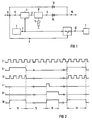
- a counter 3 is the oscillator frequency 2 supplied by the free-running oscillator 1.
- the transmission clock 6 starts the counter 3 via a device upstream of it.
- the output of the counter 3 is connected to a monoflop 8, which is connected to a temperature detection device, here a thermistor 11.
- a thermistor 11 a temperature detection device, here a thermistor 11.
- FIG. 2 Shown here is the oscillator frequency 2, which, clocked by the transmission clock 6, supplies a transmission pulse 12 which is fed to the transmission stage 7.
- the transmission pulse 12 includes a transmission time 13 which is repeated periodically after a cycle time 14.
- the counter 3 Due to the edge change at the end of the transmission time 13, the counter 3 is started via the device (not shown here), with which the first pulse with the pulse duration 5 begins to run. According to the set counter reading, the counter 3 counts the pulses of the oscillator frequency 2 supplied to it. When the counter reading is reached, ie at the end of the first pulse duration 5, the monoflop 8 is triggered by the edge change of the first pulse. A signal 4 according to FIG. 2 is present at the output of counter 3. The trigger pulse initiates a third pulse with the second pulse duration 10, the latter corresponding to the air temperature measured by the temperature detection device with the aid of the thermistor 11. At the output of the monoflop 8 there is a signal 9 according to FIG. 2 which contains the information about the air temperature.
- the transmit clock 6 is linked to the output of the monoflop 8, corresponding to signal 9, to form a third signal 16.
- This third signal 16 contains the information about both the oscillator frequency through the first pulse duration 5 and the air temperature through the third pulse with the second pulse duration 10.
- the inclusion of another counter on the integrated circuit according to the circuit described above offers a simple and inexpensive solution for additional sensor identification.
Landscapes
- Engineering & Computer Science (AREA)
- Computer Networks & Wireless Communication (AREA)
- Physics & Mathematics (AREA)
- General Physics & Mathematics (AREA)
- Radar, Positioning & Navigation (AREA)
- Remote Sensing (AREA)
- Electronic Switches (AREA)
- Measurement Of Velocity Or Position Using Acoustic Or Ultrasonic Waves (AREA)
Priority Applications (4)
| Application Number | Priority Date | Filing Date | Title |
|---|---|---|---|
| DE59008377T DE59008377D1 (de) | 1990-11-05 | 1990-11-05 | Automatische Sensorkennung bei Ultraschall-Näherungsschaltern. |
| EP90121132A EP0484566B1 (fr) | 1990-11-05 | 1990-11-05 | Reconnaissance automatique de capteur pour commutateurs de proximité |
| JP3313619A JPH04267625A (ja) | 1990-11-05 | 1991-10-31 | 超音波近接スイッチ |
| US07/788,224 US5159576A (en) | 1990-05-11 | 1991-11-05 | Automatic sensor identification for ultrasonic proximity switches |
Applications Claiming Priority (1)
| Application Number | Priority Date | Filing Date | Title |
|---|---|---|---|
| EP90121132A EP0484566B1 (fr) | 1990-11-05 | 1990-11-05 | Reconnaissance automatique de capteur pour commutateurs de proximité |
Publications (2)
| Publication Number | Publication Date |
|---|---|
| EP0484566A1 true EP0484566A1 (fr) | 1992-05-13 |
| EP0484566B1 EP0484566B1 (fr) | 1995-01-25 |
Family
ID=8204681
Family Applications (1)
| Application Number | Title | Priority Date | Filing Date |
|---|---|---|---|
| EP90121132A Expired - Lifetime EP0484566B1 (fr) | 1990-05-11 | 1990-11-05 | Reconnaissance automatique de capteur pour commutateurs de proximité |
Country Status (4)
| Country | Link |
|---|---|
| US (1) | US5159576A (fr) |
| EP (1) | EP0484566B1 (fr) |
| JP (1) | JPH04267625A (fr) |
| DE (1) | DE59008377D1 (fr) |
Cited By (1)
| Publication number | Priority date | Publication date | Assignee | Title |
|---|---|---|---|---|
| CN111398970A (zh) * | 2018-12-28 | 2020-07-10 | 北京小米移动软件有限公司 | 事件检测方法、距离传感器及终端 |
Families Citing this family (1)
| Publication number | Priority date | Publication date | Assignee | Title |
|---|---|---|---|---|
| US7162912B2 (en) * | 2004-03-29 | 2007-01-16 | Siemens Medical Solutions Usa, Inc. | Ultrasound transmit and receive path calibration methods and systems |
Citations (3)
| Publication number | Priority date | Publication date | Assignee | Title |
|---|---|---|---|---|
| DE2541901A1 (de) * | 1974-09-20 | 1976-04-15 | Hitachi Ltd | Einrichtung zur feststellung von gegenstaenden |
| EP0249952A2 (fr) * | 1986-06-18 | 1987-12-23 | Omron Tateisi Electronics Co. | Appareil de détection utilisant des ondes ultrasoniques |
| DE3703658A1 (de) * | 1987-02-06 | 1988-08-18 | Siemens Ag | Einrichtung zur ermittlung des fuellstandes einer fluessigkeit in einem behaelter, insbesondere in einem kraftfahrzeug |
Family Cites Families (1)
| Publication number | Priority date | Publication date | Assignee | Title |
|---|---|---|---|---|
| US4259548A (en) * | 1979-11-14 | 1981-03-31 | Gte Products Corporation | Apparatus for monitoring and signalling system |
-
1990
- 1990-11-05 DE DE59008377T patent/DE59008377D1/de not_active Expired - Fee Related
- 1990-11-05 EP EP90121132A patent/EP0484566B1/fr not_active Expired - Lifetime
-
1991
- 1991-10-31 JP JP3313619A patent/JPH04267625A/ja not_active Withdrawn
- 1991-11-05 US US07/788,224 patent/US5159576A/en not_active Expired - Fee Related
Patent Citations (3)
| Publication number | Priority date | Publication date | Assignee | Title |
|---|---|---|---|---|
| DE2541901A1 (de) * | 1974-09-20 | 1976-04-15 | Hitachi Ltd | Einrichtung zur feststellung von gegenstaenden |
| EP0249952A2 (fr) * | 1986-06-18 | 1987-12-23 | Omron Tateisi Electronics Co. | Appareil de détection utilisant des ondes ultrasoniques |
| DE3703658A1 (de) * | 1987-02-06 | 1988-08-18 | Siemens Ag | Einrichtung zur ermittlung des fuellstandes einer fluessigkeit in einem behaelter, insbesondere in einem kraftfahrzeug |
Non-Patent Citations (1)
| Title |
|---|
| PATENT ABSTRACTS OF JAPAN vol. 6, no. 34 (P-104)(912) 02 März 1982, & JP-A-56 151371 (MATSUSHITA) 24 November 1981, * |
Cited By (2)
| Publication number | Priority date | Publication date | Assignee | Title |
|---|---|---|---|---|
| CN111398970A (zh) * | 2018-12-28 | 2020-07-10 | 北京小米移动软件有限公司 | 事件检测方法、距离传感器及终端 |
| CN111398970B (zh) * | 2018-12-28 | 2022-04-22 | 北京小米移动软件有限公司 | 事件检测方法、距离传感器及终端 |
Also Published As
| Publication number | Publication date |
|---|---|
| DE59008377D1 (de) | 1995-03-09 |
| JPH04267625A (ja) | 1992-09-24 |
| EP0484566B1 (fr) | 1995-01-25 |
| US5159576A (en) | 1992-10-27 |
Similar Documents
| Publication | Publication Date | Title |
|---|---|---|
| DE69635586T2 (de) | Antennentreibervorrichtung für einen transponder | |
| DE19701310A1 (de) | Vorrichtung und Verfahren zur Umschaltung zwischen verschiedenen Betriebsmodi eines Meßwertaufnehmers | |
| DE19501691A1 (de) | Nicht invasives System und Verfahren zur Fluidstromüberwachung | |
| EP0393233B1 (fr) | Système de transmission de signaux | |
| DE3149789C1 (de) | Vorrichtung zur induktiven Identifizierung einer Information | |
| DE2439937C3 (de) | Schaltungsanordnung zur Erzeugung eines gegenüber einem Eingangsimpuls verzögerten Ausgangsimpulses | |
| DE19525897C1 (de) | Elektrische Schaltungsanordnung | |
| DE69212364T2 (de) | Schaltkreis zur Erkennung von Kurzschlüssen von Steuereinrichtungen für induktive Lasten | |
| DE2942134A1 (de) | Auswerteschaltung fuer einen induktivgeber | |
| EP0898368B1 (fr) | Dispositif capteur | |
| EP0519089B1 (fr) | Introduction de paramètres de service dans un commutateur de proximité prêt à servir | |
| DE3213602A1 (de) | Elektronisches geraet | |
| DE69524070T2 (de) | Geschwindigkeitsmess- und -prüfschaltung | |
| DE3779494T2 (de) | Geraet zur detektierung mittels ultraschallwellen. | |
| DE2326776A1 (de) | Doppler-radar fuer ein fahrzeug | |
| EP0981202B1 (fr) | Procédé de calibrage de la fréquence d'émission d'un détecteur de proximité à ultrasons et détecteur de proximité à ultrasons avec calibrage de la fréquence d'émission | |
| EP0484566B1 (fr) | Reconnaissance automatique de capteur pour commutateurs de proximité | |
| DE4327537C2 (de) | Sensorelement für ein serielles Bussystem | |
| DE3037722C2 (fr) | ||
| DE2750863C2 (fr) | ||
| EP0997747A2 (fr) | Méthode pour optimiser l'opération d'un commutateur de proximité et commutateur de proximité à opération optimisée | |
| DE2448533A1 (de) | Schaltungsanordnung fuer einen phasendiskriminator mit unbegrenztem fangbereich | |
| DE3689556T2 (de) | Gerät und Verfahren zur Umwandlung einer Spannung in einen digitalen Zählwert. | |
| EP0936740B1 (fr) | Commutateur de proximité inductif | |
| DE102021122843A1 (de) | Übertragungssystem und Übertragungsverfahren zur Übertragung von Daten und Energie über eine Zweidrahtleitung |
Legal Events
| Date | Code | Title | Description |
|---|---|---|---|
| PUAI | Public reference made under article 153(3) epc to a published international application that has entered the european phase |
Free format text: ORIGINAL CODE: 0009012 |
|
| 17P | Request for examination filed |
Effective date: 19901205 |
|
| AK | Designated contracting states |
Kind code of ref document: A1 Designated state(s): CH DE FR GB IT LI |
|
| 17Q | First examination report despatched |
Effective date: 19920904 |
|
| GRAA | (expected) grant |
Free format text: ORIGINAL CODE: 0009210 |
|
| AK | Designated contracting states |
Kind code of ref document: B1 Designated state(s): CH DE FR GB IT LI |
|
| REF | Corresponds to: |
Ref document number: 59008377 Country of ref document: DE Date of ref document: 19950309 |
|
| GBT | Gb: translation of ep patent filed (gb section 77(6)(a)/1977) |
Effective date: 19950303 |
|
| ITF | It: translation for a ep patent filed | ||
| ET | Fr: translation filed | ||
| PLBE | No opposition filed within time limit |
Free format text: ORIGINAL CODE: 0009261 |
|
| STAA | Information on the status of an ep patent application or granted ep patent |
Free format text: STATUS: NO OPPOSITION FILED WITHIN TIME LIMIT |
|
| 26N | No opposition filed | ||
| PGFP | Annual fee paid to national office [announced via postgrant information from national office to epo] |
Ref country code: CH Payment date: 19960216 Year of fee payment: 6 |
|
| PG25 | Lapsed in a contracting state [announced via postgrant information from national office to epo] |
Ref country code: LI Effective date: 19961130 Ref country code: CH Effective date: 19961130 |
|
| REG | Reference to a national code |
Ref country code: CH Ref legal event code: PL |
|
| PGFP | Annual fee paid to national office [announced via postgrant information from national office to epo] |
Ref country code: DE Payment date: 19990120 Year of fee payment: 9 |
|
| PGFP | Annual fee paid to national office [announced via postgrant information from national office to epo] |
Ref country code: GB Payment date: 19991116 Year of fee payment: 10 |
|
| PGFP | Annual fee paid to national office [announced via postgrant information from national office to epo] |
Ref country code: FR Payment date: 19991126 Year of fee payment: 10 |
|
| PG25 | Lapsed in a contracting state [announced via postgrant information from national office to epo] |
Ref country code: DE Free format text: LAPSE BECAUSE OF NON-PAYMENT OF DUE FEES Effective date: 20000901 |
|
| PG25 | Lapsed in a contracting state [announced via postgrant information from national office to epo] |
Ref country code: GB Free format text: LAPSE BECAUSE OF NON-PAYMENT OF DUE FEES Effective date: 20001105 |
|
| GBPC | Gb: european patent ceased through non-payment of renewal fee |
Effective date: 20001105 |
|
| PG25 | Lapsed in a contracting state [announced via postgrant information from national office to epo] |
Ref country code: FR Free format text: LAPSE BECAUSE OF NON-PAYMENT OF DUE FEES Effective date: 20010731 |
|
| REG | Reference to a national code |
Ref country code: FR Ref legal event code: ST |
|
| APAH | Appeal reference modified |
Free format text: ORIGINAL CODE: EPIDOSCREFNO |
|
| PG25 | Lapsed in a contracting state [announced via postgrant information from national office to epo] |
Ref country code: IT Free format text: LAPSE BECAUSE OF NON-PAYMENT OF DUE FEES;WARNING: LAPSES OF ITALIAN PATENTS WITH EFFECTIVE DATE BEFORE 2007 MAY HAVE OCCURRED AT ANY TIME BEFORE 2007. THE CORRECT EFFECTIVE DATE MAY BE DIFFERENT FROM THE ONE RECORDED. Effective date: 20051105 |