EP0484576B1 - Dispositif de subdivision de signaux périodiques analogiques - Google Patents
Dispositif de subdivision de signaux périodiques analogiques Download PDFInfo
- Publication number
- EP0484576B1 EP0484576B1 EP90121285A EP90121285A EP0484576B1 EP 0484576 B1 EP0484576 B1 EP 0484576B1 EP 90121285 A EP90121285 A EP 90121285A EP 90121285 A EP90121285 A EP 90121285A EP 0484576 B1 EP0484576 B1 EP 0484576B1
- Authority
- EP
- European Patent Office
- Prior art keywords
- vector
- comparison
- analog
- adders
- values
- Prior art date
- Legal status (The legal status is an assumption and is not a legal conclusion. Google has not performed a legal analysis and makes no representation as to the accuracy of the status listed.)
- Expired - Lifetime
Links
Images


Classifications
-
- H—ELECTRICITY
- H03—ELECTRONIC CIRCUITRY
- H03M—CODING; DECODING; CODE CONVERSION IN GENERAL
- H03M1/00—Analogue/digital conversion; Digital/analogue conversion
- H03M1/12—Analogue/digital converters
- H03M1/20—Increasing resolution using an n bit system to obtain n + m bits
- H03M1/202—Increasing resolution using an n bit system to obtain n + m bits by interpolation
-
- G—PHYSICS
- G01—MEASURING; TESTING
- G01D—MEASURING NOT SPECIALLY ADAPTED FOR A SPECIFIC VARIABLE; ARRANGEMENTS FOR MEASURING TWO OR MORE VARIABLES NOT COVERED IN A SINGLE OTHER SUBCLASS; TARIFF METERING APPARATUS; MEASURING OR TESTING NOT OTHERWISE PROVIDED FOR
- G01D5/00—Mechanical means for transferring the output of a sensing member; Means for converting the output of a sensing member to another variable where the form or nature of the sensing member does not constrain the means for converting; Transducers not specially adapted for a specific variable
- G01D5/12—Mechanical means for transferring the output of a sensing member; Means for converting the output of a sensing member to another variable where the form or nature of the sensing member does not constrain the means for converting; Transducers not specially adapted for a specific variable using electric or magnetic means
- G01D5/244—Mechanical means for transferring the output of a sensing member; Means for converting the output of a sensing member to another variable where the form or nature of the sensing member does not constrain the means for converting; Transducers not specially adapted for a specific variable using electric or magnetic means influencing characteristics of pulses or pulse trains; generating pulses or pulse trains
- G01D5/245—Mechanical means for transferring the output of a sensing member; Means for converting the output of a sensing member to another variable where the form or nature of the sensing member does not constrain the means for converting; Transducers not specially adapted for a specific variable using electric or magnetic means influencing characteristics of pulses or pulse trains; generating pulses or pulse trains using a variable number of pulses in a train
- G01D5/2451—Incremental encoders
-
- G—PHYSICS
- G06—COMPUTING OR CALCULATING; COUNTING
- G06G—ANALOGUE COMPUTERS
- G06G7/00—Devices in which the computing operation is performed by varying electric or magnetic quantities
- G06G7/12—Arrangements for performing computing operations, e.g. operational amplifiers specially adapted therefor
- G06G7/22—Arrangements for performing computing operations, e.g. operational amplifiers specially adapted therefor for evaluating trigonometric functions; for conversion of co-ordinates; for computations involving vector quantities
-
- G—PHYSICS
- G06—COMPUTING OR CALCULATING; COUNTING
- G06J—HYBRID COMPUTING ARRANGEMENTS
- G06J1/00—Hybrid computing arrangements
-
- H—ELECTRICITY
- H03—ELECTRONIC CIRCUITRY
- H03M—CODING; DECODING; CODE CONVERSION IN GENERAL
- H03M1/00—Analogue/digital conversion; Digital/analogue conversion
- H03M1/12—Analogue/digital converters
- H03M1/34—Analogue value compared with reference values
- H03M1/38—Analogue value compared with reference values sequentially only, e.g. successive approximation type
- H03M1/46—Analogue value compared with reference values sequentially only, e.g. successive approximation type with digital/analogue converter for supplying reference values to converter
-
- H—ELECTRICITY
- H03—ELECTRONIC CIRCUITRY
- H03M—CODING; DECODING; CODE CONVERSION IN GENERAL
- H03M1/00—Analogue/digital conversion; Digital/analogue conversion
- H03M1/12—Analogue/digital converters
- H03M1/64—Analogue/digital converters with intermediate conversion to phase of sinusoidal or similar periodical signals
- H03M1/645—Analogue/digital converters with intermediate conversion to phase of sinusoidal or similar periodical signals for position encoding, e.g. using resolvers or synchros
Definitions
- the invention relates to a device for dividing analog periodic signals according to the preamble of claim 1.
- interpolators - Such devices - also referred to as interpolators - are known from a large number of publications.
- DE-OS 27 29 697 describes an interpolation device in which, with the aid of a digital computer, the respective intermediate value is calculated from the digitized instantaneous values of two sine and cosine signals that are electrically phase-shifted by 90 ° with respect to one another.
- the invention has for its object to provide a further subdivision option that allows a high subdivision speed and requires little storage space with a high subdivision factor.
- the invention offers the advantages, among other things, that only a relatively small amount of circuitry is required, which is also easy to implement in an integrated design.
- the memory requirement is also very low, despite the high interpolation capability.
- the division speed is high and both the phase position and the amplitude can be determined in the intermediate values.
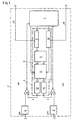
- the block diagram shown in FIG. 1 represents an interpolator 1 for approximately sinusoidal scanning signals from an incremental length or angle measuring device. Since these scanning signals are 90 ° out of phase with one another, they can be regarded as sin and cos signals.
- the task of an interpolator is to process these periodic signals. If the waveform of a signal corresponds - as here - to a trigonometric function, it is common to divide a period into degree units. This interpolation of a period into arbitrary angular fragments is to be carried out statically, dynamically and with different amplitudes of the signal.
- the interpolator described below determines the angle within a period as well as the amplitude from the two measurement signals sin and cos phase-shifted by 90 °.
- the interpolator 1 has a vector generator 2, which can synthetically generate a comparison vector that can be changed in terms of angle and amount.
- a control logic 3 acts on the vector generator 2 and, by means of an algorithm, gradually approaches the comparison vector to the instantaneous vector until there is sufficient accuracy.
- the approximation of a value to another value is known per se under the technical term "successive approximation".
- the approximation is not dependent on a single variable, as is done in A / D converters, but simultaneously on the basis of angle and absolute value comparison values.
- the analog periodic measurement signals sin and cos are buffered in sample and hold elements 4 and 5 before each processing cycle.
- the stored analog values are each fed to a comparator 6 and 7 in their signal branch.
- a logic circuit 8 is provided, which consists of angle register 9, magnitude register 10, value table 11 (sine-cosine table) and an amount adjuster 12.
- the vector generator 2 also has two digital / analog converters 13 and 14 which are controlled by the logic 8.
- the digital / analog converters 13 and 14 supply reference voltages for the comparators 6 and 7 by comparing the analog values of the measurement signals sin and cos with these reference voltages.
- the analog reference voltages at the output of the digital / analog converters 13 and 14 correspond to the digital values generated by the logic 8 for the angle and amount of the comparison vector.
- the logic 8 converts digital values for the angle and magnitude of the comparison vector into the corresponding sine and cosine values.
- the value table 11 required for this contains the necessary sine and cosine values.
- the angular resolution of the table should be two times higher than the resolution of the D / A converter.
- the comparison results of the analog values of the instantaneous and comparison vector are fed into the control logic 3 by the comparators 6 and 7.
- This control logic 3 then acts on the angle register 9, which supplies an interpolation value on an output line 15.
- the amount adjuster 12 is controlled via the amount register 10 and the amplitude value is output via a line 16.
- the magnifier 12 also receives information from the control logic 3 for quadrant detection.
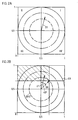
- a pie chart shown in FIGS. 2A to 2F shows different stages of the approximation of a comparison vector 20 to an instantaneous vector 21 placed here arbitrarily.
- a pie chart is particularly well suited for illustrating the conditions to be explained here, since the Measuring signals correspond to a trigonomic function.
- a period of the measurement signals sin and cos is represented by a complete circle, which is divided counterclockwise into the quadrants I, II, III and IV. The Subdivision into any angular fractions takes place with the interpolator 1 already described.
- the instantaneous vector 21 located in the first quadrant I is to be determined approximately.
- the vector generator 2 generates a comparison vector 20, which is preferably located on the bisector of the quadrant I with half the maximum amplitude.
- the maximum amplitude is represented by a full circle with the reference symbol 23, half of the maximum amplitude is accordingly represented by a circle with the reference symbol 23/2.
- the starting position of the comparison vector 20 is advantageous because from this position the probability is greatest to determine the instantaneous vector 21 in a minimal number of steps. In principle, however, the starting angle position and the magnitude of the comparison vector 20 can be chosen arbitrarily.
- the analog values of the comparison vector 20 provide the reference voltages for the comparators 6 and 7 (FIG. 1), at which the instantaneous analog values of the scanning signals sin and cos are also located, which span the instantaneous vector 21.
- the comparison in the comparators 6 and 7 provides information about either too large or too small an amount of the comparison vector 20 or too large or too small a phase angle of the comparison vector 20. This statement is made by logic signal states which are at the outputs of the Comparators 6 and 7 are available depending on the comparison.
- the angle of the comparison vector 20 must be corrected in the positive direction. If the tip of the instantaneous vector 21 is in the "top right” field, the amount of the comparison vector 20 must be corrected positively. If the tip of the instantaneous vector 21 is in the "bottom left” field, then the amount of the comparison vector 20 must be corrected negatively and if the tip of the instantaneous vector 21 is finally in the "bottom right” field, the angle must be of the comparison vector 20 can be corrected negatively.
- the tip of the instantaneous vector 21 is located in the "top left" field - that is shown hatched - so the angle of the comparison vector 20 must be corrected positively by an approximation step (see table).
- half of the previous correction step is always used for the correction step.
- the correction step of this value is half, i.e. 22.5 °.
- FIG. 2F The result is shown in FIG. 2F, in which the comparison vector 20 is shown with the previous amount at the angle of approximately 16.88 ° corrected in the negative direction.
- the new sub-coordinate system generated in this way shows that the tip of the instantaneous vector 21 is in the lower left field and the amount must now be corrected negatively by one step according to the table. The completion of this correction was no longer shown in the drawing, since it can be seen from the illustration in FIG. 2F that the vectors would almost coincide in the next step.
- the step-by-step approximation takes place - as shown - via the sine and cosine values of the comparison angle from the table mentioned at the beginning.
- the amount can be gradually adjusted via an amount adjuster designed as an additional digital / analog converter, in which the reference voltages of the other two digital / analog walkers 13 and 14 are varied.
- a magnifier 12 is shown, which is particularly advantageous as a digital circuit is trained.
- the branch for the sine signal is shown, in the same way the digital magnifier 12 is designed for the cosine branch, so that in the description, sine / cosine is written as equivalent.
- a series connection of adders 121 to 12n is provided for sine and cosine.
- the number of adders 121 to 12n corresponds to the resolution in the amount.
- Each adder 121 to 12n has two inputs E1, E2, an output A and a control input S. Depending on the control input S, output A has either the value of input E1 or the sum E1 + E2.
- the outputs A are each connected to the inputs E1 of the following adders.
- the input E1 of the first adder 121 is connected to zero, the output of the nth adder leads to the DA converter 13/14.
- the inputs E2 of the adders 121 to 12n are connected to the output of the sine / cosine table 11.
- the complete sine / cosine value is fed to the first adder 121; the subsequent adders 122 to 12n each receive "shifted to the right" by one bit, ie each have halved sine / cosine values.
- the control inputs S are connected to the amount register 10. It is thus possible to set any possible comparison vector 20 within the first quadrant I by controlling the angle 9 and magnitude register 10.
- the method can be used in all four quadrants, devices not shown in FIG. 1 being required for reversing the sign and adding an offset value.
- the control logic 3 executes the approximation algorithm described above. It effects a correction depending on the quadrant and the logic states of the comparators 6 and 7 in the amount or angle of the comparison vector 20.
- the angle or amount of the comparison vector 20 is corrected by half of the previous step. This gradual approximation continues until there is sufficient accuracy. Two working cycles must be expected to double the accuracy. After a certain completion criterion has been reached, the amplitudes and angle values are available in the corresponding registers. The counted number of angle corrections can be used as a termination criterion.
Landscapes
- Physics & Mathematics (AREA)
- Engineering & Computer Science (AREA)
- Theoretical Computer Science (AREA)
- Mathematical Physics (AREA)
- General Physics & Mathematics (AREA)
- Computer Hardware Design (AREA)
- Software Systems (AREA)
- Pure & Applied Mathematics (AREA)
- Mathematical Optimization (AREA)
- Mathematical Analysis (AREA)
- Algebra (AREA)
- Automation & Control Theory (AREA)
- Evolutionary Computation (AREA)
- Fuzzy Systems (AREA)
- Analogue/Digital Conversion (AREA)
- Amplifiers (AREA)
- Oscillators With Electromechanical Resonators (AREA)
Claims (9)
- Dispositif (1) pour la subdivision de signaux périodiques analogiques, notamment de signaux de mesure mutuellement déphasés de dispositifs de mesure de longueurs ou d'angles, au moyen d'un circuit d'interpolation, caractérisé par le fait que l'on forme un vecteur instantané (21) à l'aide de valeurs analogiques instantanées des signaux de mesure (sin, cos) mutuellement déphasés et que l'on transmet les valeurs analogiques chaque fois à un comparateur (6, 7), par le fait qu'il est prévu un générateur de vecteur (2) pour générer un vecteur de référence (20) dont l'angle et la valeur sont variables, par le fait que des valeurs amenées sous une forme analogique du vecteur de référence (20) sont transmises aux comparateurs (6, 7) mentionnés, sous la forme de tensions de référence (X, Y) et que, en fonction du résultat de la comparaison des valeurs analogiques pour le vecteur instantané (21) et pour le vecteur de référence (20), une unité logique de commande (3) déclenche sur la base d'un algorithme, à l'aide du générateur de vecteur (2), un rapprochement graduel du vecteur de référence (20) du vecteur instantané (21) et par le fait, que lorsque le rapprochement est suffisant, le générateur de vecteur (2) délivre les valeurs correspondantes d'interpolation et d'amplitude par l'intermédiaire de lignes de sortie (15, 16).
- Dispositif selon la revendication 1, caractérisé par le fait que le générateur de vecteur (2) comporte au moins une table (11) de valeurs trigonométriques, un registre de valeurs (10) et un registre d'angles (9), un circuit de valeur absolue (12) ainsi que plusieurs convertisseurs numérique/analogique (13, 14).
- Dispositif selon la revendication 2, caractérisé par le fait que le circuit de valeur absolue (12) est formé d'un convertisseur numérique/analogique qui, à l'aide du registre de valeurs (10), fait varier des tensions de référence des convertisseurs numérique/analogique (13, 14).
- Dispositif selon la revendication 2, caractérisé par le fait que le circuit de valeur absolue (12) est formé d'un circuit numérique.
- Dispositif selon la revendication 4, caractérisé par le fait que le circuit de valeur absolue (12) présente respectivement pour sinus et pour cosinus un nombre d'additionneurs (121 à 12n) qui est fonction de la résolution souhaitée, qui forment un circuit série, les sorties (A) des additionneurs (121 à 12n-1) étant connectées chaque fois aux entrées (E1) des additionneurs (122 à 12n) suivants.
- Dispositif selon la revendication 5, caractérisé par le fait que les entrées (E2) des additionneurs (121 à 12n) sont reliées à la table (11) de valeurs trigonométriques.
- Dispositif selon la revendication 5 et la revendication 6, caractérisé par le fait que la table (11) de valeurs trigonométriques est une table sinus/cosinus.
- Dispositif selon la revendication 7, caractérisé par le fait que l'on envoie au premier additionneur (121) des valeurs sinus/cosinus entières et que les additionneurs suivants (122 à 12n) reçoivent chaque fois des demi valeurs sinus/cosinus.
- Dispositif selon la revendication 5, caractérisé par le fait que les additionneurs (121 à 12n) sont reliés au registre de valeurs (10) par des entrées de commande.
Priority Applications (4)
| Application Number | Priority Date | Filing Date | Title |
|---|---|---|---|
| EP90121285A EP0484576B1 (fr) | 1990-11-07 | 1990-11-07 | Dispositif de subdivision de signaux périodiques analogiques |
| DE59010711T DE59010711D1 (de) | 1990-11-07 | 1990-11-07 | Vorrichtung zur Unterteilung von analogen periodischen Signalen |
| AT90121285T ATE152533T1 (de) | 1990-11-07 | 1990-11-07 | Vorrichtung zur unterteilung von analogen periodischen signalen |
| DE4100666A DE4100666A1 (de) | 1990-11-07 | 1991-01-11 | Vorrichtung zur unterteilung von analogen periodischen signalen |
Applications Claiming Priority (1)
| Application Number | Priority Date | Filing Date | Title |
|---|---|---|---|
| EP90121285A EP0484576B1 (fr) | 1990-11-07 | 1990-11-07 | Dispositif de subdivision de signaux périodiques analogiques |
Publications (2)
| Publication Number | Publication Date |
|---|---|
| EP0484576A1 EP0484576A1 (fr) | 1992-05-13 |
| EP0484576B1 true EP0484576B1 (fr) | 1997-05-02 |
Family
ID=8204690
Family Applications (1)
| Application Number | Title | Priority Date | Filing Date |
|---|---|---|---|
| EP90121285A Expired - Lifetime EP0484576B1 (fr) | 1990-11-07 | 1990-11-07 | Dispositif de subdivision de signaux périodiques analogiques |
Country Status (3)
| Country | Link |
|---|---|
| EP (1) | EP0484576B1 (fr) |
| AT (1) | ATE152533T1 (fr) |
| DE (2) | DE59010711D1 (fr) |
Cited By (1)
| Publication number | Priority date | Publication date | Assignee | Title |
|---|---|---|---|---|
| US6761115B2 (en) | 2001-05-07 | 2004-07-13 | Heidelberger Drunkmaschinen Ag | Clock generator for an imaging device using printing form angular position |
Families Citing this family (11)
| Publication number | Priority date | Publication date | Assignee | Title |
|---|---|---|---|---|
| DE4331151C2 (de) | 1993-09-14 | 1997-05-22 | Baumueller Nuernberg Gmbh | System zur Messung der Absolutposition des beweglichen, zyklischen Teilungsmarken-Trägers eines inkrementalen Positionsgebers |
| DE4407446C1 (de) * | 1994-03-07 | 1995-10-19 | Ibm | Verfahren und Vorrichtung zur schnellen Interpolation von Zwischenwerten aus periodischen phasenverschobenen Signalen sowie deren Verwendung |
| DE4422868C2 (de) * | 1994-06-30 | 1997-08-21 | Itt Ind Gmbh Deutsche | Vorrichtung zum Bestimmen eines Drehwinkels eines Magneten |
| DE19502276C2 (de) * | 1995-01-26 | 1999-12-09 | Gemac Ges Fuer Mikroelektronik | Interpolationsverfahren und hochauflösende digitale Interpolationseinrichtung |
| DE19539134C2 (de) * | 1995-10-20 | 2001-05-23 | Ruf Electronics Gmbh | Auswerteverfahren für berührungslos messende Weg-/Winkelaufnehmer mit sinusförmigen Spursignalen |
| DE19544948C2 (de) * | 1995-12-01 | 2002-09-26 | Gemac Ges Fuer Mikroelektronik | Digitale Interpolationseinrichtung mit Amplituden- und Nullageregelung der Eingangssignale |
| AU2001279283A1 (en) * | 2000-07-07 | 2002-01-21 | Fluidsense Corporation | Optical position sensor and position determination method |
| EP1468496B1 (fr) * | 2002-01-11 | 2006-03-08 | Dr. Johannes Heidenhain GmbH | Procede d'interpolation d'au moins deux signaux analogiques dependants d'une position, periodiques, dephases l'un par rapport a l'autre |
| DE10334869B3 (de) * | 2003-07-29 | 2004-09-16 | Tech3 E.K. | Drehwinkelsensor |
| DE102010051873B4 (de) * | 2010-11-22 | 2013-03-14 | Ic-Haus Gmbh | Integrierte Schaltungsanordnung und Verfahren zur Signalüberwachung |
| DE102011103576A1 (de) | 2011-05-30 | 2012-12-06 | Megamotive Gmbh & Co. Kg | Drehwinkelsensor |
Citations (1)
| Publication number | Priority date | Publication date | Assignee | Title |
|---|---|---|---|---|
| FR1585016A (fr) * | 1968-05-06 | 1970-01-09 |
Family Cites Families (4)
| Publication number | Priority date | Publication date | Assignee | Title |
|---|---|---|---|---|
| US3512151A (en) * | 1966-02-01 | 1970-05-12 | Vitro Corp Of America | Digital conversion systems |
| DE1690547B2 (de) * | 1968-01-19 | 1971-04-22 | Aeg Elotherm Gmbh | Vorrichtung zum einstellen der wirksamen laenge eines induk tors zum erwaermen metallischer werkstuecke |
| GB1446850A (en) * | 1972-12-01 | 1976-08-18 | Plessey Co Ltd | Signal converters |
| US4346447A (en) * | 1979-12-28 | 1982-08-24 | Nippon Kogaku K.K. | Divisional reading device for sine signals |
-
1990
- 1990-11-07 AT AT90121285T patent/ATE152533T1/de not_active IP Right Cessation
- 1990-11-07 DE DE59010711T patent/DE59010711D1/de not_active Expired - Fee Related
- 1990-11-07 EP EP90121285A patent/EP0484576B1/fr not_active Expired - Lifetime
-
1991
- 1991-01-11 DE DE4100666A patent/DE4100666A1/de not_active Withdrawn
Patent Citations (1)
| Publication number | Priority date | Publication date | Assignee | Title |
|---|---|---|---|---|
| FR1585016A (fr) * | 1968-05-06 | 1970-01-09 |
Cited By (1)
| Publication number | Priority date | Publication date | Assignee | Title |
|---|---|---|---|---|
| US6761115B2 (en) | 2001-05-07 | 2004-07-13 | Heidelberger Drunkmaschinen Ag | Clock generator for an imaging device using printing form angular position |
Also Published As
| Publication number | Publication date |
|---|---|
| DE4100666A1 (de) | 1992-05-14 |
| ATE152533T1 (de) | 1997-05-15 |
| DE59010711D1 (de) | 1997-06-05 |
| EP0484576A1 (fr) | 1992-05-13 |
Similar Documents
| Publication | Publication Date | Title |
|---|---|---|
| EP0484576B1 (fr) | Dispositif de subdivision de signaux périodiques analogiques | |
| DE3640672C2 (fr) | ||
| DE3836812C2 (fr) | ||
| DE3039901C2 (de) | Digital-Analog-Wandler | |
| EP0367947B1 (fr) | Dispositif de mesure de position comprenant un circuit de subdivision | |
| DE3131344C2 (fr) | ||
| DE69616505T2 (de) | Verfahren und gerät zur verarbeitung von winkeldaten eines kodierers | |
| WO1981001065A1 (fr) | Procede pour transformer des signaux numeriques de chrominance d'un systeme orthogonal de coordonnees de couleur en des signaux numeriques de couleur et en des signaux de saturation d'un systeme de coordonnees de couleur et circuit de transformation | |
| DE102019205679B4 (de) | Linearisierung von Eingangssignalen | |
| EP1207372B1 (fr) | Procédé et appareil pour le conditionnement d'un signal analogique périodique | |
| DE69509434T2 (de) | Interpolationsschaltung | |
| EP0006492B1 (fr) | Procédé pour l'interpolation digitale d'une période d'un signal analogique triphasé | |
| DE1574601A1 (de) | Sinus-Cosinus-Generator | |
| EP0177803B1 (fr) | Méthode et dispositif de numérisation d'un signal à haute résolution | |
| DD269269A5 (de) | Geraet fuer die anzeige des wertes einer veraenderlichen groesse | |
| EP0377771B1 (fr) | Méthode de régulation du couple pour moteurs électriques polyphasés à commutation électronique, notamment pour des moteurs synchrones | |
| DE4422868A1 (de) | Verfahren und Vorrichtung zum Bestimmen eines Drehwinkels eines Magneten | |
| EP1224511B1 (fr) | Systeme et procede pour commander une unite de positionnement, notamment des mecanismes de commande dans des machines-outils, et dispositif de melange de phases | |
| DE2620969A1 (de) | Verstaerkungsunempfindlicher digital- analogumsetzer | |
| DE19506276B4 (de) | Verfahren und Schaltungsanordnung zur Interpolation von Sensorsignalen | |
| EP0320596B1 (fr) | Système pour détecter la position avec circuit de subdivision | |
| DE69721779T2 (de) | Verfahren zum generieren der amplitude eines signals in abhängigkeit von der gewünschten funktion und wandler | |
| DE4003682A1 (de) | Schneller digital-analogwandler mit hoher aufloesung | |
| DE2119580C3 (de) | Vorrichtung zur Positionierung eines Objektes längs eines spiralförmigen Weges | |
| DE69330800T2 (de) | Absoluter kodierer mit anwendung mehrphasiger analoger signale |
Legal Events
| Date | Code | Title | Description |
|---|---|---|---|
| PUAI | Public reference made under article 153(3) epc to a published international application that has entered the european phase |
Free format text: ORIGINAL CODE: 0009012 |
|
| 17P | Request for examination filed |
Effective date: 19901122 |
|
| AK | Designated contracting states |
Kind code of ref document: A1 Designated state(s): AT CH DE ES FR GB IT LI NL SE |
|
| 17Q | First examination report despatched |
Effective date: 19950411 |
|
| GRAG | Despatch of communication of intention to grant |
Free format text: ORIGINAL CODE: EPIDOS AGRA |
|
| GRAH | Despatch of communication of intention to grant a patent |
Free format text: ORIGINAL CODE: EPIDOS IGRA |
|
| GRAH | Despatch of communication of intention to grant a patent |
Free format text: ORIGINAL CODE: EPIDOS IGRA |
|
| ITF | It: translation for a ep patent filed | ||
| RBV | Designated contracting states (corrected) |
Designated state(s): AT CH DE FR GB IT LI |
|
| GRAA | (expected) grant |
Free format text: ORIGINAL CODE: 0009210 |
|
| AK | Designated contracting states |
Kind code of ref document: B1 Designated state(s): AT CH DE FR GB IT LI |
|
| REF | Corresponds to: |
Ref document number: 152533 Country of ref document: AT Date of ref document: 19970515 Kind code of ref document: T |
|
| REG | Reference to a national code |
Ref country code: CH Ref legal event code: NV Representative=s name: TROESCH SCHEIDEGGER WERNER AG Ref country code: CH Ref legal event code: EP |
|
| ET | Fr: translation filed | ||
| GBT | Gb: translation of ep patent filed (gb section 77(6)(a)/1977) |
Effective date: 19970509 |
|
| REF | Corresponds to: |
Ref document number: 59010711 Country of ref document: DE Date of ref document: 19970605 |
|
| PLBE | No opposition filed within time limit |
Free format text: ORIGINAL CODE: 0009261 |
|
| STAA | Information on the status of an ep patent application or granted ep patent |
Free format text: STATUS: NO OPPOSITION FILED WITHIN TIME LIMIT |
|
| 26N | No opposition filed | ||
| PGFP | Annual fee paid to national office [announced via postgrant information from national office to epo] |
Ref country code: CH Payment date: 19991014 Year of fee payment: 10 |
|
| PGFP | Annual fee paid to national office [announced via postgrant information from national office to epo] |
Ref country code: AT Payment date: 19991021 Year of fee payment: 10 |
|
| PGFP | Annual fee paid to national office [announced via postgrant information from national office to epo] |
Ref country code: FR Payment date: 19991027 Year of fee payment: 10 |
|
| PG25 | Lapsed in a contracting state [announced via postgrant information from national office to epo] |
Ref country code: AT Free format text: LAPSE BECAUSE OF NON-PAYMENT OF DUE FEES Effective date: 20001107 |
|
| PG25 | Lapsed in a contracting state [announced via postgrant information from national office to epo] |
Ref country code: LI Free format text: LAPSE BECAUSE OF NON-PAYMENT OF DUE FEES Effective date: 20001130 Ref country code: CH Free format text: LAPSE BECAUSE OF NON-PAYMENT OF DUE FEES Effective date: 20001130 |
|
| REG | Reference to a national code |
Ref country code: CH Ref legal event code: PL |
|
| PG25 | Lapsed in a contracting state [announced via postgrant information from national office to epo] |
Ref country code: FR Free format text: LAPSE BECAUSE OF NON-PAYMENT OF DUE FEES Effective date: 20010731 |
|
| REG | Reference to a national code |
Ref country code: FR Ref legal event code: ST |
|
| REG | Reference to a national code |
Ref country code: GB Ref legal event code: IF02 |
|
| PGFP | Annual fee paid to national office [announced via postgrant information from national office to epo] |
Ref country code: GB Payment date: 20031029 Year of fee payment: 14 |
|
| PG25 | Lapsed in a contracting state [announced via postgrant information from national office to epo] |
Ref country code: GB Free format text: LAPSE BECAUSE OF NON-PAYMENT OF DUE FEES Effective date: 20041107 |
|
| GBPC | Gb: european patent ceased through non-payment of renewal fee |
Effective date: 20041107 |
|
| PG25 | Lapsed in a contracting state [announced via postgrant information from national office to epo] |
Ref country code: IT Free format text: LAPSE BECAUSE OF NON-PAYMENT OF DUE FEES;WARNING: LAPSES OF ITALIAN PATENTS WITH EFFECTIVE DATE BEFORE 2007 MAY HAVE OCCURRED AT ANY TIME BEFORE 2007. THE CORRECT EFFECTIVE DATE MAY BE DIFFERENT FROM THE ONE RECORDED. Effective date: 20051107 |
|
| PGFP | Annual fee paid to national office [announced via postgrant information from national office to epo] |
Ref country code: DE Payment date: 20051110 Year of fee payment: 16 |
|
| PG25 | Lapsed in a contracting state [announced via postgrant information from national office to epo] |
Ref country code: DE Free format text: LAPSE BECAUSE OF NON-PAYMENT OF DUE FEES Effective date: 20070601 |