EP0484584A1 - Cage de laminoir - Google Patents
Cage de laminoir Download PDFInfo
- Publication number
- EP0484584A1 EP0484584A1 EP90121457A EP90121457A EP0484584A1 EP 0484584 A1 EP0484584 A1 EP 0484584A1 EP 90121457 A EP90121457 A EP 90121457A EP 90121457 A EP90121457 A EP 90121457A EP 0484584 A1 EP0484584 A1 EP 0484584A1
- Authority
- EP
- European Patent Office
- Prior art keywords
- rolls
- roll
- support
- work
- roll stand
- Prior art date
- Legal status (The legal status is an assumption and is not a legal conclusion. Google has not performed a legal analysis and makes no representation as to the accuracy of the status listed.)
- Granted
Links
Images

Classifications
-
- B—PERFORMING OPERATIONS; TRANSPORTING
- B21—MECHANICAL METAL-WORKING WITHOUT ESSENTIALLY REMOVING MATERIAL; PUNCHING METAL
- B21B—ROLLING OF METAL
- B21B13/00—Metal-rolling stands, i.e. an assembly composed of a stand frame, rolls, and accessories
- B21B13/14—Metal-rolling stands, i.e. an assembly composed of a stand frame, rolls, and accessories having counter-pressure devices acting on rolls to inhibit deflection of same under load; Back-up rolls
- B21B13/147—Cluster mills, e.g. Sendzimir mills, Rohn mills, i.e. each work roll being supported by two rolls only arranged symmetrically with respect to the plane passing through the working rolls
Definitions
- the invention relates to a roll stand for the cold and hot rolling of flat material, in particular for reducing and skin-passaging metal strips, with two cambered work rolls and support rolls for the work rolls.
- the invention has for its object to provide a rolling stand of the type described in the introduction, in which a stepless change of the crowning in the roll gap is possible quickly and easily during the rolling process.
- This object is achieved by the invention in a roll stand of the generic type in that two support rolls are provided for the lower and / or upper work roll, which are pivotably mounted for the continuous change of the support effect.
- the support rollers are preferably arranged on a circular path so as to be pivotable about the center of the lower or upper work roller.
- the crowning of the work rolls is designed for 100% of the maximum rolling force, so that when the rolling force drops, the deflection of the lower and / or upper work roll can be changed so that the sum of the bending deformations on the upper and lower work roll corresponds to the sum of the curvatures used . It will preferably be limited to providing two supports only for the lower work roll.
- the upper work roll is then supported in a known manner by only a single backup roll and equipped with an adjustment system. Assuming that the upper back-up roll and the two lower back-up rolls have the same diameter and the two lower back-up rolls are arranged with an exit angle of 45 ° to the center of the lower work rolls, the diameter ratio of the back-up rolls / work rolls is approx.2.4.
- the two lower support rollers have the same support effect as the only upper support roller.
- an increased spreading effect is achieved, which, however, permits an increased deflection of the lower work roll in order to always correct the bending line and consequently crown to achieve an ideal roll gap.
- the invention provides that the lower and / or upper work roll with at least one intermediate roll interposed outer support rollers are supported, wherein at least two support rollers are pivotally mounted on a circular path around the center of the intermediate roller assigned to them for the stepless change of the support effect.
- a height adjustment of the entire rolling stand can also be provided for the adjustment of the pass line.
- the support rollers are preferably pivotably supported with segment-like bearing blocks with the interposition of rolling elements in a semi-cylindrical bearing shell. Storage in sliding or hydrostatic bearing shells is also possible.
- the measures described achieve smooth pivoting of the support rollers. This is especially true when actuators, e.g. on the pedestals and on the stands of the roll stand.
- actuators e.g. on the pedestals and on the stands of the roll stand.
- hydraulically or pneumatically actuated cylinder piston assemblies or mechanically actuated spindles are articulated.
- the invention further provides that the support rollers and possibly intermediate rollers and the actuators are arranged axially symmetrically to a vertical axis of symmetry leading through the work rollers.
- the support rollers can be pivoted individually or together by an equal or different pivot angle by means of the actuators. This makes it possible to continuously change the crowning for every rolling process, even if it is not a matter of reducing but merely dressing the rolling stock.
- the invention also relates to a method for changing the crowning of one by means of two support rollers in each case supported work roll in the roll gap during the rolling process depending on the respective rolling force, after which the support effect is varied by pivoting the two pivotally mounted support rolls by a pivot angle predetermined by the respective rolling force such that the sum of the deflections on the upper and lower work roll the sum corresponds to the unused crowning.
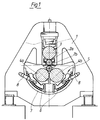
- the figures show a roll stand 1 for the cold and hot rolling of flat material, in particular for reducing and skin-passaging metal strips.
- this roll stand has two cambered work rolls 2a, 2b and support rolls 3, 4 for these work rolls.
- Two support rollers 4a, 4b are provided for the lower work roll 2b.
- a backup roller 3 is sufficient for the upper work roller 2a. According to a variant, however, two backup rollers 3a, 3b are also provided.
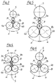
- the two support rollers 3a, 3b and 4a, 4b are pivotally mounted on a circular path B around the center M of the lower and upper work rollers 2a, 2b for continuously changing their support effect.
- the support rollers 4a, 4b are mounted in segment-like bearing blocks 5.
- the segment-like bearing blocks 5 are pivotally mounted in a semi-cylindrical bearing shell 7 with the interposition of rolling elements 6.
- actuators 8 - according to the exemplary embodiment, hydraulically actuatable cylinder piston arrangements - are articulated.
- the lower work roll 2b is supported with the interposition of an intermediate roller 9 on the two support rollers 4a, 4b, the support rollers 4a, 4b in this case on a circular path B1 around the center M1 of the intermediate roller 9 for continuous change the support is pivoted.
- the support rollers 3a, 3b or 4a, 4b and, if appropriate, the intermediate roller 9 and the actuating drives 8 are arranged axially symmetrically with respect to a vertical axis of symmetry S leading through the work rollers 2a, 2b.
- the support rollers 3a, 3b and 4a, 4b can be pivoted individually or together by an identical or different pivoting angle ⁇ by means of the actuators 8.
- the swiveling of the two lower support rolls 4a, 4b (possibly also the two upper support rolls) continuously and quickly achieves a continuous change in the crowning of the work rolls 2a, 2b in the roll gap during the rolling process.
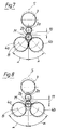
- FIGS. 7 and 8 show the elastic bending behavior of the rolls at a pivoting position of 45 ° or 60 °.
- the cambered work rolls 2a, 2b and support rolls 3, 4a, 4b are shown cylindrical and the elastic deflection is exaggerated. It can be seen that the elastic deflection 11 in the 60 ° swivel position is greater than the deflection 10 in the 45 ° swivel position.
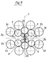
- the application of the teaching according to the invention is also possible for multi-roll mill stands, taking into account the diameter ratios.
- the 20-roll mill shown in Fig. 9 has, for example, eight support rollers 3, 4, of which two lower and two upper support rollers 4a, 4b and 3a, 3b around the center M1 of the intermediate roller 9 assigned to them for continuous change the support is pivoted.
- the roll stand can be driven on the work rolls or backup rolls.
- the rolling can be supported by appropriate strip pulls in front of and behind the roll gap.
Landscapes
- Engineering & Computer Science (AREA)
- Mechanical Engineering (AREA)
- Metal Rolling (AREA)
- Reduction Rolling/Reduction Stand/Operation Of Reduction Machine (AREA)
Priority Applications (3)
| Application Number | Priority Date | Filing Date | Title |
|---|---|---|---|
| EP19900121457 EP0484584B1 (fr) | 1990-11-09 | 1990-11-09 | Cage de laminoir |
| DE90121457T DE59003031D1 (de) | 1990-11-09 | 1990-11-09 | Walzgerüst. |
| CA 2055184 CA2055184A1 (fr) | 1990-11-09 | 1991-11-08 | Support de laminoir |
Applications Claiming Priority (1)
| Application Number | Priority Date | Filing Date | Title |
|---|---|---|---|
| EP19900121457 EP0484584B1 (fr) | 1990-11-09 | 1990-11-09 | Cage de laminoir |
Publications (2)
| Publication Number | Publication Date |
|---|---|
| EP0484584A1 true EP0484584A1 (fr) | 1992-05-13 |
| EP0484584B1 EP0484584B1 (fr) | 1993-10-06 |
Family
ID=8204698
Family Applications (1)
| Application Number | Title | Priority Date | Filing Date |
|---|---|---|---|
| EP19900121457 Expired - Lifetime EP0484584B1 (fr) | 1990-11-09 | 1990-11-09 | Cage de laminoir |
Country Status (3)
| Country | Link |
|---|---|
| EP (1) | EP0484584B1 (fr) |
| CA (1) | CA2055184A1 (fr) |
| DE (1) | DE59003031D1 (fr) |
Citations (7)
| Publication number | Priority date | Publication date | Assignee | Title |
|---|---|---|---|---|
| DE566683C (de) * | 1929-01-29 | 1934-10-31 | Heraeus Vacuumschmelze A G | Walzwerk mit Stuetz- und Arbeitswalzen |
| GB523777A (en) * | 1938-12-14 | 1940-07-23 | Robert Bass | Rolling-mills |
| DE955131C (de) * | 1943-02-25 | 1956-12-27 | Tadeusz Sendzimer | Walzwerksanordnung |
| GB1049797A (en) * | 1963-02-28 | 1966-11-30 | Lee Wilson Engineering S A | Rolling mill and method |
| DE2401757A1 (de) * | 1974-01-14 | 1975-07-24 | Inst Tschernoj Metallurg | Walzgeruest |
| FR2346064A1 (fr) * | 1976-03-30 | 1977-10-28 | Nars Ab Oy | Procede de compensation de la flexion subie par un rouleau de calandre |
| SU1514435A1 (ru) * | 1988-01-28 | 1989-10-15 | Dn Metall Inst | Многовалковая прокатная клеть |
-
1990
- 1990-11-09 EP EP19900121457 patent/EP0484584B1/fr not_active Expired - Lifetime
- 1990-11-09 DE DE90121457T patent/DE59003031D1/de not_active Expired - Fee Related
-
1991
- 1991-11-08 CA CA 2055184 patent/CA2055184A1/fr not_active Abandoned
Patent Citations (7)
| Publication number | Priority date | Publication date | Assignee | Title |
|---|---|---|---|---|
| DE566683C (de) * | 1929-01-29 | 1934-10-31 | Heraeus Vacuumschmelze A G | Walzwerk mit Stuetz- und Arbeitswalzen |
| GB523777A (en) * | 1938-12-14 | 1940-07-23 | Robert Bass | Rolling-mills |
| DE955131C (de) * | 1943-02-25 | 1956-12-27 | Tadeusz Sendzimer | Walzwerksanordnung |
| GB1049797A (en) * | 1963-02-28 | 1966-11-30 | Lee Wilson Engineering S A | Rolling mill and method |
| DE2401757A1 (de) * | 1974-01-14 | 1975-07-24 | Inst Tschernoj Metallurg | Walzgeruest |
| FR2346064A1 (fr) * | 1976-03-30 | 1977-10-28 | Nars Ab Oy | Procede de compensation de la flexion subie par un rouleau de calandre |
| SU1514435A1 (ru) * | 1988-01-28 | 1989-10-15 | Dn Metall Inst | Многовалковая прокатная клеть |
Also Published As
| Publication number | Publication date |
|---|---|
| CA2055184A1 (fr) | 1992-05-10 |
| EP0484584B1 (fr) | 1993-10-06 |
| DE59003031D1 (de) | 1993-11-11 |
Similar Documents
| Publication | Publication Date | Title |
|---|---|---|
| DE602004007631T2 (de) | Verfahren zum ändern der konfiguration eines walzgerüstes sowie ein zur durchführung des verfahrens geeignetes walzgerüst | |
| DE3212070C2 (de) | Walzgerüst mit einer Vorrichtung zur Einhaltung der Ebenheit des gewalzten Guts | |
| DE3609290A1 (de) | Schraegwalzwerk | |
| EP0112969B2 (fr) | Procédé pour laminer des rubans métalliques | |
| DE19816602C1 (de) | Walzgerüst mit axial verschiebbaren Walzen | |
| EP0602492B1 (fr) | Laminoir à plusieurs cylindres | |
| DE2443002C3 (de) | Dreiwalzen-Blechrundbiegemaschine zum Biegen zylinderischer oder kegeliger Blechschüsse | |
| DE19807115C1 (de) | Walze | |
| EP0665067A1 (fr) | Cage de laminoir à cylindres multiples du type à montants de préférence avec serrage hydraulique direct | |
| DE69924466T2 (de) | Abstreifvorrichtung für flüssigkeiten | |
| DE29780451U1 (de) | Hochgenaues Walzwerk mit zweidimensionaler Biegungssteuerung | |
| EP0484584B1 (fr) | Cage de laminoir | |
| DE2335809A1 (de) | Walzgeruest | |
| DE68910549T2 (de) | Walzgerüst mit fliegend gelagerten Walzen und mit konvergierenden Walzenachsen. | |
| AT390392B (de) | Walzwerk, insbesondere kaltwalzwerk | |
| DE2034490A1 (en) | Roller pivot bearing compensator - hydraulically operated | |
| DE3638331C2 (de) | Walzgerüst zum Walzen von Flachmaterial mit einem Paar von axial verschiebbaren Arbeitswalzen | |
| DE3736683C3 (de) | Mehrrollen-Walzgerüst | |
| DE3210325A1 (de) | Walzgeruest | |
| DE69731671T2 (de) | Walzwerk zum walzen von bändern oder blechen | |
| AT390741B (de) | Walzwerk, insbesondere kaltwalzwerk | |
| DE559414C (de) | Walzwerk mit zwei Arbeitswalzen, die sich gegen innen mit Waelzkoerpern versehene Stuetzrollen abstuetzen | |
| DE918091C (de) | Kalander | |
| EP0663246B1 (fr) | Cage de laminoir à cylindres réglables dans plans horizontaux | |
| DE1936769A1 (de) | Vorrichtung zur Balligkeitssteuerung der Arbeitswalzen in einem Duo-Metallwalzwerk |
Legal Events
| Date | Code | Title | Description |
|---|---|---|---|
| PUAI | Public reference made under article 153(3) epc to a published international application that has entered the european phase |
Free format text: ORIGINAL CODE: 0009012 |
|
| AK | Designated contracting states |
Kind code of ref document: A1 Designated state(s): AT BE CH DE DK ES FR GB GR IT LI LU NL SE |
|
| 17P | Request for examination filed |
Effective date: 19920411 |
|
| RBV | Designated contracting states (corrected) |
Designated state(s): BE DE FR GB |
|
| 17Q | First examination report despatched |
Effective date: 19921005 |
|
| GRAA | (expected) grant |
Free format text: ORIGINAL CODE: 0009210 |
|
| AK | Designated contracting states |
Kind code of ref document: B1 Designated state(s): BE DE FR GB |
|
| PG25 | Lapsed in a contracting state [announced via postgrant information from national office to epo] |
Ref country code: BE Effective date: 19931006 |
|
| REF | Corresponds to: |
Ref document number: 59003031 Country of ref document: DE Date of ref document: 19931111 |
|
| GBT | Gb: translation of ep patent filed (gb section 77(6)(a)/1977) |
Effective date: 19931115 |
|
| ET | Fr: translation filed | ||
| PG25 | Lapsed in a contracting state [announced via postgrant information from national office to epo] |
Ref country code: DE Effective date: 19940802 |
|
| PLBE | No opposition filed within time limit |
Free format text: ORIGINAL CODE: 0009261 |
|
| STAA | Information on the status of an ep patent application or granted ep patent |
Free format text: STATUS: NO OPPOSITION FILED WITHIN TIME LIMIT |
|
| 26N | No opposition filed | ||
| PG25 | Lapsed in a contracting state [announced via postgrant information from national office to epo] |
Ref country code: FR Effective date: 19940930 |
|
| PG25 | Lapsed in a contracting state [announced via postgrant information from national office to epo] |
Ref country code: GB Effective date: 19941109 |
|
| REG | Reference to a national code |
Ref country code: FR Ref legal event code: ST |
|
| GBPC | Gb: european patent ceased through non-payment of renewal fee |
Effective date: 19941109 |
|
| PG25 | Lapsed in a contracting state [announced via postgrant information from national office to epo] |
Ref country code: FR Effective date: 19931130 |