EP0484587A1 - Relais électromagnétique avec module de commande - Google Patents
Relais électromagnétique avec module de commande Download PDFInfo
- Publication number
- EP0484587A1 EP0484587A1 EP90121500A EP90121500A EP0484587A1 EP 0484587 A1 EP0484587 A1 EP 0484587A1 EP 90121500 A EP90121500 A EP 90121500A EP 90121500 A EP90121500 A EP 90121500A EP 0484587 A1 EP0484587 A1 EP 0484587A1
- Authority
- EP
- European Patent Office
- Prior art keywords
- integrated circuit
- flat
- relay
- relay according
- housing
- Prior art date
- Legal status (The legal status is an assumption and is not a legal conclusion. Google has not performed a legal analysis and makes no representation as to the accuracy of the status listed.)
- Granted
Links
- 238000001816 cooling Methods 0.000 claims abstract description 13
- 230000008878 coupling Effects 0.000 claims description 31
- 238000010168 coupling process Methods 0.000 claims description 31
- 238000005859 coupling reaction Methods 0.000 claims description 31
- 150000001875 compounds Chemical class 0.000 claims description 5
- 239000004065 semiconductor Substances 0.000 claims description 2
- 239000000758 substrate Substances 0.000 claims description 2
- 238000005266 casting Methods 0.000 claims 2
- 230000017525 heat dissipation Effects 0.000 description 3
- 238000010438 heat treatment Methods 0.000 description 3
- 238000004382 potting Methods 0.000 description 3
- 238000007789 sealing Methods 0.000 description 2
- 238000004873 anchoring Methods 0.000 description 1
- 230000033228 biological regulation Effects 0.000 description 1
- 230000009931 harmful effect Effects 0.000 description 1
- 238000009434 installation Methods 0.000 description 1
- 239000000463 material Substances 0.000 description 1
Images
Classifications
-
- H—ELECTRICITY
- H01—ELECTRIC ELEMENTS
- H01H—ELECTRIC SWITCHES; RELAYS; SELECTORS; EMERGENCY PROTECTIVE DEVICES
- H01H50/00—Details of electromagnetic relays
- H01H50/12—Ventilating; Cooling; Heating
-
- H—ELECTRICITY
- H01—ELECTRIC ELEMENTS
- H01H—ELECTRIC SWITCHES; RELAYS; SELECTORS; EMERGENCY PROTECTIVE DEVICES
- H01H50/00—Details of electromagnetic relays
- H01H50/02—Bases; Casings; Covers
- H01H50/021—Bases; Casings; Covers structurally combining a relay and an electronic component, e.g. varistor, RC circuit
Definitions
- the invention relates to an electromagnetic relay with a housing, with connection elements led out of the housing and with a control module arranged in the housing in the form of an integrated circuit.
- relays for certain purposes to regulate the control voltage or the coil current with a high thermal load both due to high switching currents inside the relay and due to high ambient temperatures.
- a typical application for such relays is the motor vehicle, where the contacts have to carry very high currents at low voltages, while the ambient temperature fluctuates greatly and can be, for example, up to 125 ° C. If you add the self-heating of the relay, there are thermal loads of up to 200 ° C, which an integrated circuit cannot cope with. Precisely because of the strong temperature fluctuations, however, regulation of the control voltage is desired or necessary, and in this case the control module would also like to be accommodated in the relay housing in order to save space and installation.
- the object of the invention is to provide a relay of the type mentioned with an integrated circuit housed in the relay housing as a control module, in which the harmful effects of elevated temperatures, be it due to the heat loss in the coil and contacts, be it through the self-heating of the circuit, can be eliminated or at least significantly reduced with as little design effort as possible.
- connection elements designed as a flat plug is thermally coupled to the substrate of the integrated circuit as a cooling plate on a coupling section of its flat side.
- the flat plugs as used for example for motor vehicle relays, have a width of 6.3 or 9.5 mm and a thickness of 0.8 to 1.2 mm. With such a large cross-section, good heat dissipation is possible since the wiring connected to the flat plug via a jack or a cable lug carries the heat on.
- the large cross section of the tabs for the connection elements of the contacts is important because of the high switching currents, while the coil connections per se only have to carry a relatively low current. According to the standard, however, the coil connection tabs have the same cross-section. For the control module to be connected to the coil, there is thus an additional advantageous use of this large plug cross section, which is present anyway, for heat dissipation.
- the coupling section of the flat connector is expediently arranged above it in such a way that the circuit is shielded from heat sources in the relay.
- the thermal coupling between the integrated circuit and the flat connector can be carried out by a thermal paste or by other means if the IC and the flat connector are mounted as separate parts.
- the integrated circuit can also be arranged flat between parallel coupling sections of two flat plugs in thermally conductive coupling, it being firmly connected to at least one of the flat plugs. In this case, heat is dissipated via two flat plugs and is therefore even more effective. If the materials permit, the integrated circuit can be firmly connected to both flat plugs, one connection of the circuit being contacted with one of the flat plugs. However, if a relative movement due to the thermal expansion of the different parts has to be taken into account, only one of the flat plugs is firmly connected to the IC, while the second flat plug is connected loosely, but also thermally conductive, and contacted via a flexible connection with the corresponding connection element of the IC .
- the integrated circuit can be arranged together with the respective coupling section of the flat connector or the flat connector at least partially within the base plate, preferably embedded. Different types of fastening are possible.
- the remaining openings are sealed by potting compound, for example covering and sealing the flexible connections. This is particularly advantageous if the flat plug with the integrated circuit is inserted or embedded in the region of a recess which is only accessible from the outside of the relay housing. In this case, subsequent sealing is definitely desirable.
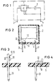
- Figure 1 basically shows the connection of a control module in the form of an integrated circuit 1 for controlling a coil 2 in a relay.
- the coil connections 3 and 4 lead to the outside, which are connected to the coil 2 in the interior of the relay partly directly and partly indirectly via the three connections 11, 12 and 13 of the integrated circuit.
- FIG. 2 shows a schematic sectional illustration of a relay housing with a cap 6 and a base plate 5, the arrangement of the coil 2 and its connection to the coil connections 3 and 4, which are designed as tabs 31 and 41.
- the flat plug 31 has on the inside of the base plate 5 a bent coupling section 32 which shields the IC 10 arranged in a recess 51 of the base plate 5 against the coil and against other heat sources, not shown, in the relay.
- a good thermal connection between the IC 10 and the coupling section 32 of the flat connector is produced with a thermal paste 52.
- FIGS. 3 and 4 show an integrated circuit 1 which is produced as a one-piece component with a coupling section 32 in the form of a cooling plate, the flat plug 31 being formed directly on this cooling plate.
- the cooling plate in the form of the coupling section 32 directly forms the circuit connection 11 from FIG. 1, while the two connections 12 and 13 are led out separately.
- the cooling plate in the form of the coupling section 32 can be anchored vertically according to FIG. 3 with the flat plug 31 or angled according to FIG. 4 in the base plate 5.
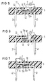
- FIG. 5 to 7 show an embodiment in which an angled coupling section 32 of the tab 31 and an angled second coupling section 42 of the tab 41 overlap in parallel.
- the integrated circuit 10 is inserted between these two coupling sections in the overlap region, it being firmly connected to the coupling section 32, but is only loosely connected to the coupling section 42, but is also thermally conductive.
- the thermal conduction can also be ensured here by a thermal paste. Since the coupling section 42 also requires an electrical connection to the connection 13 of the IC 10, this connection 13a is designed to be flexible and contacted separately.
- the two tabs with their coupling sections 32 and 42 are firmly anchored in the base plate 5 by inserting or embedding, the flexible connection 13a and the connection 12 led to the coil being accessible in an opening 7 to the interior of the housing. If necessary, this can The opening can be subsequently sealed or encapsulated by potting compound or the like.
- FIG. 6 A similar arrangement of the flat plugs 31 and 41 is shown in FIG. 6, in which case a fixed coupling is provided between the IC 10 and the coupling section 42. A loose coupling is thus formed between the IC 10 and the coupling section 32; therefore, in this case, the connection 11 of the IC is contacted with the coupling section 32 via a flexible connection 11a.
- FIG. 7 the arrangement of FIG. 6 has been modified to the extent that embedding or other anchoring of the coupling sections 32 and 42 is now carried out in such a way that a recess 8 is accessible from the outside.
- this recess can be subsequently sealed with potting compound 9.
Landscapes
- Physics & Mathematics (AREA)
- Electromagnetism (AREA)
- Cooling Or The Like Of Electrical Apparatus (AREA)
- Burglar Alarm Systems (AREA)
- Air Bags (AREA)
- Valve Device For Special Equipments (AREA)
- Shielding Devices Or Components To Electric Or Magnetic Fields (AREA)
- Fuses (AREA)
- Connection Or Junction Boxes (AREA)
Priority Applications (8)
| Application Number | Priority Date | Filing Date | Title |
|---|---|---|---|
| AT90121500T ATE125640T1 (de) | 1990-11-09 | 1990-11-09 | Elektromagnetisches relais mit regelbaustein. |
| EP90121500A EP0484587B1 (fr) | 1990-11-09 | 1990-11-09 | Relais électromagnétique avec module de commande |
| ES90121500T ES2074511T3 (es) | 1990-11-09 | 1990-11-09 | Rele electromagnetico con modulo de regulacion. |
| DE59009448T DE59009448D1 (de) | 1990-11-09 | 1990-11-09 | Elektromagnetisches Relais mit Regelbaustein. |
| US07/783,808 US5170322A (en) | 1990-11-09 | 1991-10-29 | Electromagnetic relay system having a control module thermally coupled to a terminal element acting as a heat shield and cooling plate |
| CA002055004A CA2055004A1 (fr) | 1990-11-09 | 1991-11-07 | Relais electromagnetique a module de commande |
| PT99459A PT99459B (pt) | 1990-11-09 | 1991-11-08 | Rele electromagnetico com um componente de regulacao |
| JP3292665A JPH0589758A (ja) | 1990-11-09 | 1991-11-08 | 電磁式のリレー |
Applications Claiming Priority (1)
| Application Number | Priority Date | Filing Date | Title |
|---|---|---|---|
| EP90121500A EP0484587B1 (fr) | 1990-11-09 | 1990-11-09 | Relais électromagnétique avec module de commande |
Publications (2)
| Publication Number | Publication Date |
|---|---|
| EP0484587A1 true EP0484587A1 (fr) | 1992-05-13 |
| EP0484587B1 EP0484587B1 (fr) | 1995-07-26 |
Family
ID=8204703
Family Applications (1)
| Application Number | Title | Priority Date | Filing Date |
|---|---|---|---|
| EP90121500A Expired - Lifetime EP0484587B1 (fr) | 1990-11-09 | 1990-11-09 | Relais électromagnétique avec module de commande |
Country Status (8)
| Country | Link |
|---|---|
| US (1) | US5170322A (fr) |
| EP (1) | EP0484587B1 (fr) |
| JP (1) | JPH0589758A (fr) |
| AT (1) | ATE125640T1 (fr) |
| CA (1) | CA2055004A1 (fr) |
| DE (1) | DE59009448D1 (fr) |
| ES (1) | ES2074511T3 (fr) |
| PT (1) | PT99459B (fr) |
Cited By (3)
| Publication number | Priority date | Publication date | Assignee | Title |
|---|---|---|---|---|
| WO1996041428A1 (fr) * | 1995-06-07 | 1996-12-19 | National Digital Electronics, Inc. | Systeme de telemetrie et de commande comprenant un relais intelligent |
| WO1997042642A1 (fr) * | 1996-05-07 | 1997-11-13 | Siemens Aktiengesellschaft | Relais hybride |
| EP2133962A1 (fr) * | 2008-06-13 | 2009-12-16 | Delphi Technologies, Inc. | Relais de véhicule automobile |
Families Citing this family (13)
| Publication number | Priority date | Publication date | Assignee | Title |
|---|---|---|---|---|
| US5555484A (en) * | 1994-04-04 | 1996-09-10 | Von Duprin, Inc. | Electromagnetic door holder system |
| DE19522126C2 (de) * | 1995-06-19 | 1999-01-28 | Hella Kg Hueck & Co | Elektronischer Lastschalter für ein Kraftfahrzeug, beispielsweise Blinkgeber |
| DE19636932C1 (de) * | 1996-09-11 | 1998-01-02 | Siemens Ag | Relais mit Überlastschutz |
| DE19837241C1 (de) * | 1998-08-17 | 2000-07-27 | Tyco Electronics Logistics Ag | Elektromagnetisches Relais |
| TWI243636B (en) * | 2004-06-10 | 2005-11-11 | Delta Electronics Inc | Assembling structure of electronic apparatus and assembling method therefor |
| JP2007184132A (ja) * | 2006-01-05 | 2007-07-19 | Nec Tokin Corp | 電磁継電器 |
| JP5131218B2 (ja) * | 2008-09-12 | 2013-01-30 | アンデン株式会社 | 電磁継電器 |
| JP5131219B2 (ja) * | 2009-02-02 | 2013-01-30 | アンデン株式会社 | 電磁継電器 |
| US7933126B2 (en) * | 2009-03-11 | 2011-04-26 | Schneider Electric USA, Inc. | Solid state relay with internal heat sink |
| DE102009029476B4 (de) | 2009-09-15 | 2012-11-08 | Lisa Dräxlmaier GmbH | Elektronische Vorrichtung zum Schalten von Strömen und Herstellungsverfahren für dieselbe |
| US8552824B1 (en) * | 2012-04-03 | 2013-10-08 | Hamilton Sundstrand Corporation | Integrated planar electromechanical contactors |
| US20170062793A1 (en) * | 2015-08-24 | 2017-03-02 | Elitise Llc | Contactor assembly for battery module |
| JP3204154U (ja) * | 2016-02-26 | 2016-05-19 | ホライズン株式会社 | 充電用コネクタ |
Citations (3)
| Publication number | Priority date | Publication date | Assignee | Title |
|---|---|---|---|---|
| US4060847A (en) * | 1976-03-11 | 1977-11-29 | Power Management Corporation | Cooling arrangement for electrical power contactor |
| DE3614919A1 (de) * | 1986-05-02 | 1987-11-05 | Hengstler Bauelemente | Elektromagnetisches kleinstrelais |
| EP0281950A1 (fr) * | 1987-03-13 | 1988-09-14 | Siemens Aktiengesellschaft | Relais électromagnétique |
Family Cites Families (2)
| Publication number | Priority date | Publication date | Assignee | Title |
|---|---|---|---|---|
| DE3716102A1 (de) * | 1987-05-14 | 1988-11-24 | Bosch Gmbh Robert | Elektrisches schalt- und steuergeraet |
| US5018050A (en) * | 1987-11-17 | 1991-05-21 | Omron Tateisi Electronics Co. | Solid state relay |
-
1990
- 1990-11-09 ES ES90121500T patent/ES2074511T3/es not_active Expired - Lifetime
- 1990-11-09 EP EP90121500A patent/EP0484587B1/fr not_active Expired - Lifetime
- 1990-11-09 DE DE59009448T patent/DE59009448D1/de not_active Expired - Fee Related
- 1990-11-09 AT AT90121500T patent/ATE125640T1/de not_active IP Right Cessation
-
1991
- 1991-10-29 US US07/783,808 patent/US5170322A/en not_active Expired - Fee Related
- 1991-11-07 CA CA002055004A patent/CA2055004A1/fr not_active Abandoned
- 1991-11-08 JP JP3292665A patent/JPH0589758A/ja active Pending
- 1991-11-08 PT PT99459A patent/PT99459B/pt not_active IP Right Cessation
Patent Citations (3)
| Publication number | Priority date | Publication date | Assignee | Title |
|---|---|---|---|---|
| US4060847A (en) * | 1976-03-11 | 1977-11-29 | Power Management Corporation | Cooling arrangement for electrical power contactor |
| DE3614919A1 (de) * | 1986-05-02 | 1987-11-05 | Hengstler Bauelemente | Elektromagnetisches kleinstrelais |
| EP0281950A1 (fr) * | 1987-03-13 | 1988-09-14 | Siemens Aktiengesellschaft | Relais électromagnétique |
Cited By (3)
| Publication number | Priority date | Publication date | Assignee | Title |
|---|---|---|---|---|
| WO1996041428A1 (fr) * | 1995-06-07 | 1996-12-19 | National Digital Electronics, Inc. | Systeme de telemetrie et de commande comprenant un relais intelligent |
| WO1997042642A1 (fr) * | 1996-05-07 | 1997-11-13 | Siemens Aktiengesellschaft | Relais hybride |
| EP2133962A1 (fr) * | 2008-06-13 | 2009-12-16 | Delphi Technologies, Inc. | Relais de véhicule automobile |
Also Published As
| Publication number | Publication date |
|---|---|
| EP0484587B1 (fr) | 1995-07-26 |
| DE59009448D1 (de) | 1995-08-31 |
| JPH0589758A (ja) | 1993-04-09 |
| PT99459B (pt) | 1999-02-26 |
| CA2055004A1 (fr) | 1992-05-10 |
| ES2074511T3 (es) | 1995-09-16 |
| US5170322A (en) | 1992-12-08 |
| ATE125640T1 (de) | 1995-08-15 |
| PT99459A (pt) | 1993-11-30 |
Similar Documents
| Publication | Publication Date | Title |
|---|---|---|
| EP0484587B1 (fr) | Relais électromagnétique avec module de commande | |
| DE102008012570B4 (de) | Leistungshalbleitermodul-System, Leistungshalbleitermodulanordnung und Verfahren zur Herstellung einer Leistungshalbleitermodulanordnung | |
| DE19955100B4 (de) | Auf einer Leiterplatte integrierte Halbleitereinrichtung | |
| EP0588793B1 (fr) | Boitier pour composants electroniques d'automobile | |
| DE102016102327B4 (de) | Gehäuse für ein elektronisches Bauelement sowie Lasermodul | |
| DE19634202C2 (de) | Halbleitervorrichtung | |
| DE10056832A1 (de) | Halbleiterbauteil-Moduleinheit | |
| DE29620596U1 (de) | Sockel für eine integrierte Schaltung | |
| WO1993009656A1 (fr) | Appareil electrique, en particulier appareil de connexion et de commande pour vehicules automobiles | |
| EP0750452A1 (fr) | Commutateur électronique de puissance pour des véhicules automobiles | |
| DE102006000169A1 (de) | Entladungslampen-Beleuchtungsgerät | |
| DE102006052872A1 (de) | Elektrisches Leistungsmodul | |
| DE19806801C2 (de) | Elektrische Schaltunganordnung | |
| DE3731413C2 (fr) | ||
| DE3219571A1 (de) | Gehaeuse fuer elektronische schaltungen | |
| DE102014205604A1 (de) | Leiterplatte mit Spuleneinheit und ein Montageverfahren dafür | |
| DE19501895C2 (de) | Elektrische Schaltungsanordnung für Kraftfahrzeuge | |
| DE8508595U1 (de) | Gleichstromstellergerät | |
| DE102005059082A1 (de) | Verfahren zum Vergießen elektrischer Komponenten und Gehäuseanordnung | |
| EP1010583B1 (fr) | Dispositif électronique | |
| DE102005026233B4 (de) | Elektrisches Leistungsmodul | |
| EP0320618A1 (fr) | Boîtier pour un thyristor de puissance du type GTO | |
| DE102021110991A1 (de) | EMV-Filtervorrichtung mit einer gehäuseseitig festgelegten Leiterstruktur; sowie Leistungselektronikmodul | |
| DE8704499U1 (de) | Elektrische Baueinheit | |
| DE19612599A1 (de) | Anordnung zur Befestigung eines Kabelbaums an einer Trägerplatte |
Legal Events
| Date | Code | Title | Description |
|---|---|---|---|
| PUAI | Public reference made under article 153(3) epc to a published international application that has entered the european phase |
Free format text: ORIGINAL CODE: 0009012 |
|
| 17P | Request for examination filed |
Effective date: 19901205 |
|
| AK | Designated contracting states |
Kind code of ref document: A1 Designated state(s): AT BE CH DE DK ES FR GB GR IT LI LU NL SE |
|
| RBV | Designated contracting states (corrected) |
Designated state(s): AT CH DE ES FR GB IT LI |
|
| 17Q | First examination report despatched |
Effective date: 19940322 |
|
| GRAA | (expected) grant |
Free format text: ORIGINAL CODE: 0009210 |
|
| AK | Designated contracting states |
Kind code of ref document: B1 Designated state(s): AT CH DE ES FR GB IT LI |
|
| REF | Corresponds to: |
Ref document number: 125640 Country of ref document: AT Date of ref document: 19950815 Kind code of ref document: T |
|
| REF | Corresponds to: |
Ref document number: 59009448 Country of ref document: DE Date of ref document: 19950831 |
|
| ET | Fr: translation filed | ||
| REG | Reference to a national code |
Ref country code: ES Ref legal event code: FG2A Ref document number: 2074511 Country of ref document: ES Kind code of ref document: T3 |
|
| ITF | It: translation for a ep patent filed | ||
| GBT | Gb: translation of ep patent filed (gb section 77(6)(a)/1977) |
Effective date: 19951010 |
|
| PLBE | No opposition filed within time limit |
Free format text: ORIGINAL CODE: 0009261 |
|
| STAA | Information on the status of an ep patent application or granted ep patent |
Free format text: STATUS: NO OPPOSITION FILED WITHIN TIME LIMIT |
|
| 26N | No opposition filed | ||
| PGFP | Annual fee paid to national office [announced via postgrant information from national office to epo] |
Ref country code: CH Payment date: 19980219 Year of fee payment: 8 |
|
| PGFP | Annual fee paid to national office [announced via postgrant information from national office to epo] |
Ref country code: AT Payment date: 19981021 Year of fee payment: 9 |
|
| PGFP | Annual fee paid to national office [announced via postgrant information from national office to epo] |
Ref country code: ES Payment date: 19981110 Year of fee payment: 9 |
|
| PG25 | Lapsed in a contracting state [announced via postgrant information from national office to epo] |
Ref country code: LI Free format text: LAPSE BECAUSE OF NON-PAYMENT OF DUE FEES Effective date: 19981130 Ref country code: CH Free format text: LAPSE BECAUSE OF NON-PAYMENT OF DUE FEES Effective date: 19981130 |
|
| REG | Reference to a national code |
Ref country code: CH Ref legal event code: PL |
|
| PG25 | Lapsed in a contracting state [announced via postgrant information from national office to epo] |
Ref country code: AT Free format text: LAPSE BECAUSE OF NON-PAYMENT OF DUE FEES Effective date: 19991109 |
|
| PG25 | Lapsed in a contracting state [announced via postgrant information from national office to epo] |
Ref country code: ES Free format text: LAPSE BECAUSE OF NON-PAYMENT OF DUE FEES Effective date: 19991110 |
|
| REG | Reference to a national code |
Ref country code: GB Ref legal event code: 732E |
|
| REG | Reference to a national code |
Ref country code: GB Ref legal event code: IF02 |
|
| PGFP | Annual fee paid to national office [announced via postgrant information from national office to epo] |
Ref country code: GB Payment date: 20031002 Year of fee payment: 14 |
|
| PGFP | Annual fee paid to national office [announced via postgrant information from national office to epo] |
Ref country code: FR Payment date: 20031105 Year of fee payment: 14 |
|
| PGFP | Annual fee paid to national office [announced via postgrant information from national office to epo] |
Ref country code: DE Payment date: 20031128 Year of fee payment: 14 |
|
| REG | Reference to a national code |
Ref country code: ES Ref legal event code: FD2A Effective date: 20001214 |
|
| PG25 | Lapsed in a contracting state [announced via postgrant information from national office to epo] |
Ref country code: GB Free format text: LAPSE BECAUSE OF NON-PAYMENT OF DUE FEES Effective date: 20041109 |
|
| PG25 | Lapsed in a contracting state [announced via postgrant information from national office to epo] |
Ref country code: DE Free format text: LAPSE BECAUSE OF NON-PAYMENT OF DUE FEES Effective date: 20050601 |
|
| GBPC | Gb: european patent ceased through non-payment of renewal fee |
Effective date: 20041109 |
|
| PG25 | Lapsed in a contracting state [announced via postgrant information from national office to epo] |
Ref country code: FR Free format text: LAPSE BECAUSE OF NON-PAYMENT OF DUE FEES Effective date: 20050729 |
|
| REG | Reference to a national code |
Ref country code: FR Ref legal event code: ST |
|
| PG25 | Lapsed in a contracting state [announced via postgrant information from national office to epo] |
Ref country code: IT Free format text: LAPSE BECAUSE OF NON-PAYMENT OF DUE FEES;WARNING: LAPSES OF ITALIAN PATENTS WITH EFFECTIVE DATE BEFORE 2007 MAY HAVE OCCURRED AT ANY TIME BEFORE 2007. THE CORRECT EFFECTIVE DATE MAY BE DIFFERENT FROM THE ONE RECORDED. Effective date: 20051109 |